Types of welded joints and seams
Often the cause of defects among novice welders is incorrectly selected welded joints. Which is not surprising, since since the first welding, more than a hundred varieties have been developed. They are not difficult to understand, since welds and joints are combined into several groups according to execution technique, position of parts and other characteristics.
What is a welded joint
Beginners mistakenly believe that the concepts of weld and connection are equivalent. In fact, a seam is a place where two workpieces are joined with molten metal, followed by cooling. A welded joint consists of three sections that have been exposed to high temperature. These include:
It is important not to confuse two completely different concepts - a weld seam and a welded joint!
A weld is a place where two workpieces are joined with molten metal, followed by cooling. A welded joint consists of three sections that have been exposed to high temperature.
Types of welded joints
Depending on how the workpieces are arranged among themselves, the main types of welding joints include:
Butt
The easiest seams to make, even for novice welders. They connect workpieces adjacent to each other at their ends, placed in the same plane or on a flat surface. When welding parts with different thicknesses, displacement of the surfaces is allowed. The butt welding method is used to weld sheet metal structures, tanks, and pipes. Compared to other welded joints, the time required to complete the work and the consumption of materials are reduced, but the edges must be carefully prepared.
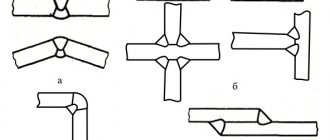
Corner
These are welded joints of two metal parts at any angle. If the workpieces are of different thicknesses, the thick-walled one is placed at the bottom so that burns and undercuts do not appear on the thin-walled one, the weld pool is created by melting the metal of the thick workpiece. To increase the strength of the connection, seams are applied on both sides. The inner corner is welded with low current so that a rounding does not form on the outside.
It is convenient to make corner welded joints using the “boat” method. The workpieces are grabbed at the desired angle, then installed as if it were a sailing boat. After melting, the metal will spread evenly on both sides without the formation of defects.
Frames of small buildings, containers, canopies, and truck bodies are welded using the corner method. In addition, structural parts are installed in hard-to-reach places.
Overlapping
Such welds connect parallel metal plates, which are superimposed on one another with slight overlap. To increase tensile strength and prevent moisture from penetrating inside, welding is performed on both sides. This method can be used to join sheets up to 12 mm thick. To make lap joints, the welder does not require high qualifications, since there is no danger of burn-through and there is no need to prepare the edges. The disadvantage is considered to be increased metal consumption.
T-bar
This is a welded connection between the end of one part and the side surface of another at a right or slight angle. If the thickness of the workpiece is more than 4 mm, welding is carried out on both sides with careful preparation of the edges of the vertical plate. T-joints are used primarily in the assembly of load-bearing structures. Therefore, if it is possible to change the position, it is better to weld critical components “in a boat”.
End
When making such connections, the ends of the workpieces are welded, which are tightly adjacent to one another or diverge from the joint at an angle of no more than 30⁰. The method is used in the production of casings, ventilation ducts, containers, metal cabinets, etc. The advantages of the end-type welding joints include a low probability of the formation of burns and internal stresses causing deformation. Disadvantages include excessive material consumption and the occurrence of corrosion when water penetrates between the sheets through seam defects.
The choice of welded joint depends on the location of the workpieces relative to each other.
Seam geometry
The weld leg must comply with the geometric parameters specified in the regulatory documents. They are also used to carry out mathematical calculations of the main geometric characteristics using formulas and tables.
Weld parameters.
The geometry of the welding joint is determined by the type of connection. The cross-section of the joint will depend on the type and size of the parts being welded.
In production, all parameters and strength of joints are calculated using formulas. At home, you can limit yourself to ready-made templates.
The most convenient and widespread is the universal template, which is a set of plates fastened together. Applying them alternately to the surface of the products, select the one that fits most tightly to them.
When welding metal structures that do not require high strength and reliability, the minimum weld size is determined based on the thickness of the metal.
After performing the calculations, select the required current and voltage, and then begin welding.
Classification of welds
Even in the same type of connection, welding seams may differ in configuration, length, technology, etc. Therefore, in regulatory documents they are grouped by parameters.
By position in space
According to their spatial position, welds can be:
By configuration
This group includes three types of welding seams, which depend on the shape of the joints. They are rectilinear, curvilinear, ring (spiral). The configuration of the seams does not depend on the spatial position of the workpieces.
By degree of convexity
Based on the cross-sectional shape, welds are classified as:
By length
This classification includes continuous and intermittent welds, which are performed in segments of 10 - 30 cm, but the total length of the connection is taken into account. Based on the location of the welding sections, intermittent types are called:
Depending on the length, welds are classified into three categories:
By number of passes
Regardless of the type, welds are performed in one or more passes. The choice of option is determined by the thickness of the metal and the required strength. Each pass deposits one bead. If they are placed at the same level, a layer of welded seam is formed.
Parts up to 5 mm thick are connected with single-pass seams. Corner joints made from workpieces with walls 6–8 mm are welded in one layer, and butt joints in two. Multilayer seams are used when working with thick-walled elements and to prevent thermal deformation.
Dependence on weld type
There are several options for coupling metal elements into a single structure. Based on the location of the parts to be connected, the following types of welds are distinguished:
- Butt welding is the most rational, since the stress concentration in the seam with this method is minimal. The ends of the parts are welded, as a result, one part of the product continues the other.
- Angular - the connected elements are located perpendicular to each other. The strength here largely depends on the correctly calculated ultimate force.
- T-shaped - similar to corner with the only difference being that the parts are welded at the ends. This track is durable, economical and easy to make.
- Overlapping - the edges of the interlocking parts are somewhat on top of each other. This type allows you to strengthen the connection and is used where you need to weld metal with a thickness of no more than 5 mm.
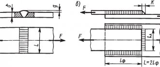
Before you begin calculating the strength of the future adhesion, you need to calculate its cross-sectional area. To do this, the length of the welded joint is multiplied by its thickness.
Overlapping sheets
To calculate the shear stress, use the formula:
Where:
- P—seam load, N;
- 'av - permissible shear stress, Pa;
- 0.7k - thickness of the seam in the most dangerous section, cm;
- l is the length of the weld path, mm.
When joining with an overlap, cutting the edges is not required.
The load value P is:
When calculating, the minimum cross-sectional area of the welded track in diameter is taken into account. This is due to the fact that welding materials can exceed the base metal in strength.
Corner designs
Such connections are calculated based on their cross-section, the smallest, i.e., in the most dangerous place of the track. The bending stability index of a simple fillet weld, when it is loaded only with moment M, is calculated as follows:
Where:
- Wc is the moment of resistance of the dangerous section of the track (seam);
- M is the bending moment.
Corner structures are calculated based on their cross section.
And the shear stress of a simple corner joint will be written as follows:
Where:
- M—loading moment at shear;
- Fc = 0.7kl - cross-sectional area of the track in a dangerous place, mm²;
- P is the permissible load on the track.
When calculating fillet welds for shear, the generally accepted expression is used:
Where:
- N is the maximum load pressing on the clutch line;
- c is the coefficient of working environment conditions, the value is indicated in standardized tables;
- ßf, ßz are constant values that do not depend on the grade of metal, ßz = 1, ßf = 0.7;
- Rwf - shear resistance, tabular value for different materials;
- Rwz—resistance at the joint line; standard, constant tabular values;
- kf is the thickness of the track, measured along the fusion line;
- Ywf - for a joint of material with a resistance of 4200 kgf/cm² is 0.85;
- Ywz - 0.85 for all steel grades;
- lw is the total length of the joint, reduced by 10 mm.
When determining the pull-off length of the welding bond, the force directed towards the center of gravity must be taken into account. In this case, the cross-sectional area is chosen in the most dangerous place of the track, i.e. the smallest.
T-seams
The condition for the adhesion strength of T-joints made end-to-end and subjected to tension P and moment M looks like this:
The formula for the same, but not butt, but fillet weld:
T-seams can be one-sided or two-sided.
If the T-joint will be subject to bending and torque, then the equation applies:
The torsional and bending force are respectively determined by the following formulas:
And
Welding at the joint
The calculation of a butt seam, which will work in compression or tension, is performed according to the equation:
Where:
- l is the length of the welding track, mm;
- P—load acting on the joint, N;
- s—thickness of the parts to be connected, mm;
- ' р1сж1 - permissible tensile or compressive stress for adhesion, Pa.
The permissible effective load P will be:
Butt coupling working in bending is calculated using the formula:
Where:
- M is the bending moment, N/mm;
- Wc is the moment of resistance of the design section.
If the weld stress arises from both bending M and compression or tension P, then it is determined by the equation:
Requirements for welds
Requirements for seams depend on operating conditions, types of load, metal properties, welding technology, etc. GOST standards have been developed to classify them according to specific conditions. For example, the requirements for manual welding joints are given in GOST 5264-80.
Common to all seams, regardless of conditions, include:
In order for the seam to be of high quality, it is necessary to follow the technology of metal preparation and welding.
You can learn about the length and thickness of seams depending on the design features and grade of metal, quality control methods, etc. from thematic SNiPs, which are easy to find in the public domain. The information obtained can be used as a cheat sheet when performing complex work.
What affects the quality of a welded joint?
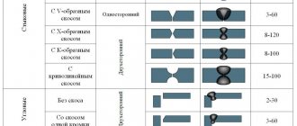
The quality of a welding connection depends not only on adherence to technology, but also on the preparation of parts. Even the shape of the edges affects the quality of the connection. Regardless of the type of connection, preparation is carried out in the following order:
The dependence of the cutting angle, the amount of bluntness and the gap on the metal thickness is shown in the table:
Knowledge of the main types of joints and the principles of their application will help you choose the right welding seam for each specific case. To improve your skills, it is useful to follow technological news so as not to miss the emergence of new alloys and welding methods.
Source
Auxiliary signs
GOST 20295-85.
welded steel pipes for main gas and oil pipelines. technical specifications (as amended n 1, 2) The welding designation in the drawing will be incomplete and incomprehensible without auxiliary symbols. The table below shows auxiliary signs, indicating what each of them means when applied to the diagram.
Using auxiliary signs, specialists when drawing up diagrams of metal structures indicate the following information:
- The need to eliminate the convexity at the joint that arose during welding work.
- The need to ensure a smooth transition to the main surface. This can be done by mechanical or manual processing of all existing irregularities.
- The welding line of the elements must remain open.
- The contour of the welding joint must be closed.
- First, it is necessary to install the prepared parts and only then begin the welding process.
- It is necessary to make a point or intermittent seam, its location should be chain.
- It is necessary to create a connecting joint in a checkerboard pattern.
Each additional designation of a weld is regulated by GOST and indicates clarifications that should be additionally carried out at the joint.
Notes on notation
In order to see how a weld is indicated on the drawing and correctly read all the technical information, you should remember some nuances:
- the side from which the one-sided joint is welded is the front surface;
- in a double-sided connection, the edges of which are asymmetrical relative to one another, the front side is considered to be the one with which the main seam is made;
- the front surface of a double-sided joint, in which the edges are prepared symmetrically, can be protruded by either side.
All additional symbols and signs are applied to the diagrams with thin solid lines
When creating drawings, you should pay attention to the fact that all signs must have the same height as the numbers
The table below provides some examples of how additional symbols are used in drawings.
| Name | What does the joint look like? | Image on drawings |
| Single-sided flat connection, V-shaped edge preparation | ||
| The seam is convex on both sides, the edges are separated in the form of a V symbol | ||
| Concave corner joint | ||
| Butt joint on one side, the edges are separated in a V-shape with a flat underweld seam | ||
| The butt weld is one-sided, the edges are separated using the V method with a large bluntness and an underweld seam | ||
| Single-sided flat joint with V-shaped edge separation. The gain was removed using additional processing | ||
| Corner connection with a smooth transition to the base metal from the seam itself |
Description and types of welded joints
The process of joining two or more parts into one permanent structure by melting metal with an electric arc, a torch flame, plastic deformation, or a combination of deformation and heat is called welding. A connection made by welding is called a welded joint. Since the first welding, more than a hundred varieties have been developed, which are divided into groups according to types, execution techniques, arrangement of parts relative to each other, cross-sectional shape, length, and shape of the surfaces being welded.
Classification and types of welds and joints
According to GOST 5264-80, there are main types of welded joints, their structural elements and dimensions.
All welding joints are divided into groups according to the following parameters:
Seam position in space
Location in space means in what position the seam is located relative to the electrode during welding.
Vertical - welding in a position where the welding parts are at an angle from 60 to 120 o and require experience and high qualifications from the welder.
By configuration
Welding seams are:
By length
By length they are divided into:
Spot and intermittent welds are often preliminary, when the welder initially “grabs” the parts together, and then welds it completely.
By number of passes
Based on the number of passes, seams are divided into single-layer or single-pass - the work is done in one pass and one layer.
Multilayer in the case when the layer is made in several times or passes (a double-sided seam will necessarily have at least two passes).
By degree of convexity
Depending on the welding materials used, welding modes, welding speed and width of the edge grooves, they are divided into:
By type of welding
The type of welding is divided depending on the welding machine and the environment in which the work takes place.
The most basic types are:
Manual arc welding - work by hand, with an electrode;
Automatic welding – performed by a special automatic welding machine. Metal is melted either by an electric arc or a gas burner (usually the electric arc method). A flux mixture is fed into the weld pool, which covers the melt zone like a blanket and prevents the formation of oxides and filler wire, the metal of which melts and forms a weld. The speed and direction of movement of the electrode are set automatically. After crystallization of the metal and its cooling, the flux mixture remains on the surface in the form of slag and is removed mechanically. Such connections, due to the absence of violation of welding technology, are very durable. The process ensures high speed and quality.
Automatic welding circuit
Gas shielded welding is performed in an inert gas environment (usually argon) or in a carbon dioxide environment. Welding can be automatic or semi-automatic. Quality is achieved by protecting the weld pool with carbon dioxide or argon from the formation of an oxide film. Air oxygen does not enter the melt zone and does not degrade the quality. Welding is carried out with a fireproof electrode (usually tungsten). This type of surface connection is suitable for welding work on stainless steel, titanium, and aluminum.
Type of connections os (bp) os (sp) ds (bz) ds (zk)
Welded joints are divided into the following types:
welded connections made on one side (one-sided welding) - os (ss) and on both sides (double-sided welding) - ds (bs);
welded joints made on a removable or remaining lining, backing ring - sp (mb) and without a lining (in weight) - bp (nb);
welded joints made with stripping the weld root - zk (gg), without stripping the weld root - bz (ng);
welded joints made with gas protection of the weld root (gas injection) - gz (gb);
Types of connections os, ds
How are the properties of a welded joint determined?
Methods for determining the mechanical properties of a welded joint as a whole and its sections, as well as the properties of the deposited material, are regulated by the provisions of GOST 6996-66. Tests are carried out to determine the quality and development of technology in large-scale and mass production.
According to GOST, tests are carried out to determine quality in the following ways:
To determine quality during acceptance, non-destructive methods are used:
Visual and measuring control - checking by external inspection for the presence of welding defects in the control zone.
Ultrasonic method – ultrasonic frequency waves are emitted in the control zone. Reflecting from the back side of the metal, the waves return and are received by the sensor. Wave reflection does not occur at the defect site and this is visible on the indicator.
Capillary method - based on the ability of certain liquids (penetrants) to penetrate microcracks. Liquids contain coloring pigments and the presence of defects is determined by the appearance of paint on the surface.
Pneumatic method - air is supplied under pressure, and on the other side a soap solution. The presence of fistulas and lack of penetration is determined by the formation of bubbles.
Hydraulic - pour in liquid and hold until the liquid fills the microcracks. Then the product is taken out and tapped with a hammer. Defects are determined by the presence of leaks.
For steel parts, the magnetic method is used - the product is magnetized with direct current and metal powder is scattered on top. The powder, under the influence of a magnetic field, lines up along the magnetic lines. If there are defects, the powder reveals them by distorting the pattern.
Classification of welded joints
A welded joint is a permanent connection made by welding. The welded joint (Fig. 1) includes three characteristic zones of metal in the product formed as a result of welding: weld zone 1, fusion zone 2, heat-affected zone 3, as well as part of the base metal 4 adjacent to the heat-affected zone.
Rice. 1. Welded joint
A weld is a section of a welded joint formed as a result of crystallization of molten metal.
Weld metal is an alloy formed by molten base and deposited metals or only remelted base metal.
Base metal - the metal of the parts being welded.
Fusion zone is a zone where partially melted metal grains are located at the boundary of the base metal and the weld metal. This heating zone is below the melting point. Unmelted grains in this zone are separated by liquid layers associated with the liquid metal of the weld pool, and elements introduced into the bath with additional metal or welding materials are able to penetrate into these layers. Therefore, the chemical composition of this zone is different from the chemical composition of the base metal.
Thermal affected zone is a section of the base metal that has not undergone melting, the structure and properties of which have changed as a result of heating during welding, surfacing or cutting.
The type of welded joint determines the relative position of the welded elements. There are: butt, corner, tee, lap and end welded joints.
Available provisions
Spatial positions during welding have four options. The easiest one to achieve is the horizontal bottom position. The most difficult position is also considered to be the horizontal position of the seam, but located at the top, and called shelf. The seam in the horizontal direction is not necessarily performed at the bottom or at the top. It can be located in the center of a vertical wall. The remaining option belongs to the vertical position.
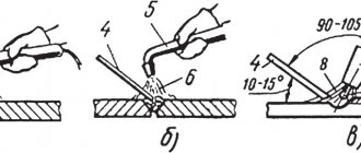
Different welding positions in space have their own nuances when performing welding. The location of the electrodes depends on the type of position.
Lower
This position is the most desirable for any welder. This option is used when simple small parts are welded or if strict requirements are not imposed on the quality of the seam. The position of the electrode in this type is vertical. In this position, welding is possible both on one side and on both sides.
The quality of the weld in the lower position is influenced by the thickness of the parts being welded, the size of the gap between them, and the magnitude of the current. This method has high productivity. The disadvantage is the occurrence of burns. In the lower position, you can use butt and corner joint methods.
Horizontal
In this form, the connected elements are in a vertical plane. The weld seam is horizontal. The electrode belongs to the horizontal plane, but is located perpendicular to the seam. Difficulty during operation is caused by the possible splashing of liquid metal from the weld pool and falling under its own weight directly onto the edge located below. Before starting work, it is necessary to carry out preparatory work, namely, cutting the edges.
Vertical
The parts to be welded are placed in a vertical plane so that the seam between them is also vertical. The electrode is located in a horizontal plane perpendicular to the seam.
The problem of drops of hot metal falling down remains. Work should be performed exclusively on a short arc. This will prevent liquid metal from entering the weld crater. It is recommended to use electrodes with a coating that increases the viscosity of the contents of the weld pit. This will significantly reduce the flow of molten metal down.
Of the two existing methods of movement, if possible, you should choose the movement from bottom to top. Then the inevitably flowing metal will, when solidified, form a step that prevents its further sliding. This takes a long time. When using the top-down method, productivity increases at the expense of reduced seam quality.
Ceiling
In essence, it is a horizontal seam located in an inconvenient place to work. The welder has to remain in a difficult position with his arm outstretched for a long time. This, of course, does not depend on qualifications, but experienced craftsmen have their own techniques that facilitate the welding process in this position. In any case, it is necessary to take breaks periodically.
The welding position of the parts will be horizontal, and the electrode will be vertical. The seam is located at the bottom of the edges. The main risk of getting a poor-quality weld is that liquid metal flows down, but does not always get into the weld pool.
When using the ceiling welding method, you should use a low current and a minimally short arc. The electrodes must have a small diameter and a refractory coating that retains metal droplets due to surface tension. This type of welding is especially undesirable when parts of small thickness are to be joined.
Types of connections
Butt joint is a welded connection of two elements adjacent to each other with end surfaces and located in the same plane or on the same surface (Fig. 2). The surfaces of the elements may be slightly displaced when connecting sheets of different thicknesses (see Fig. 2, b).
Rice. 2. Butt joints
Corner connection is a welded connection of two elements located at an angle and welded at the junction of their edges (Fig. 3).
Rice. 3. Corner joints
T-joint is a welded joint in which the end of one element adjoins at an angle and is welded to the side surface of another element (Fig. 4).
Rice. 4. T-joint
Lap joint is a welded joint in which the welded elements are located parallel and partially overlap each other (Fig. 5, a, b). The absence of the danger of burn-through during welding facilitates the use of high-performance welding modes. The use of overlap joints facilitates the assembly and welding of seams performed during the installation of structures (assembly seams).
End connection is a welded connection in which the side surfaces of the welded elements are adjacent to each other (Fig. 5, e).
Welds are divided according to different criteria: by type of seam, by length, by method of execution, by spatial position and by the shape of the edges.
Types of seams SSH, USH
By type, welds are divided into butt welds (SW), corner welds (USH), and slotted welds.
Butt weld SS is a welded seam of a butt joint.
Fillet weld USH is a welded seam of a corner, lap or T-joint.
Types of seams. Butt weld - SSH, Fillet weld - USH
The following characteristics of a weld are distinguished: width, convexity, concavity and root of the weld.
Weld width e is the distance between the visible fusion lines of the weld (see Fig. 2, a). The convexity of the weld g is determined by the distance between the plane passing through the visible lines of the boundary of the weld with the base metal and the surface of the weld, measured at the place of the greatest convexity (see Fig. 2, a; 4, a). The concavity of the weld T is determined by the distance between the plane passing through the visible lines of the boundary of the weld with the base metal and the surface of the weld, measured at the place of greatest concavity (see Fig. 2, c; 3, c). The concavity of the root of a butt weld is a defect on the reverse side of a single-sided weld. The root of the weld is the part of the weld furthest from its front surface (see Fig. 2, b; 4, a). Essentially, this is the reverse side of the seam, in which the width e1 and height g1 of the reverse roller are distinguished (see Fig. 2, a).
A fillet weld has the following dimensional characteristics: leg, thickness, design height. The leg of the fillet weld k is determined by the shortest distance from the surface of one of the parts being welded to the boundary of the fillet weld on the surface of the second part being welded (see Fig. 3, c; 4, a). The leg is set as a parameter that must be maintained during welding. Fillet weld thickness a is the greatest distance from the surface of the fillet weld to the point of maximum penetration of the base metal. To assess the strength of a welded joint, use the calculated height of the fillet weld - p. For fillet welds, a concave shape of the weld surface with a smooth transition to the base metal is more favorable
According to the method of execution, welding is distinguished: single-sided and double-sided, single-layer and multi-layer. One-sided welding of a butt welded joint is performed with through penetration of the edges on a backing or without a backing (in weight). Double-sided welding is performed with stripping (removal) of the weld root (mechanical processing) before welding the reverse side of the welded joint or without stripping the weld root. When double-sided welding, it is often necessary to turn the product or weld in a difficult ceiling position.
A multilayer weld is used when welding thick metal, as well as to reduce the heat-affected zone. The weld layer is understood as a part of the weld metal, which consists of one or more beads located at the same level of the cross-section of the weld. Bead - weld metal deposited in one pass. A welding pass means a single movement in one direction of the heat source during welding or surfacing.
Pattern - Multilayer seam