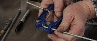
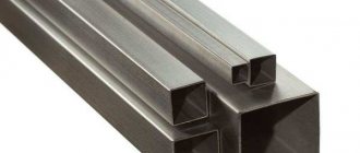
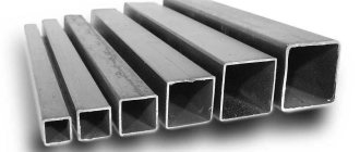
Construction of a permanent garage made of brick, cinder block, other block material or using monolithic technology is an undertaking that is not affordable for everyone. However, there is an option that can be implemented by almost any car owner who has the skills of plumbing and welding. This is a garage with a frame made of a profile pipe, covered with sheet material, which can be built with the help of a construction team or with your own hands. For this purpose, welded rectangular or square corrugated pipes made of “black” steel are usually used. The use of a rectangular pipe is rational if the direction of action of the main force, for example, a strong wind, is known. For cladding, the most practical and economical material is corrugated sheeting.
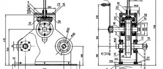
Drawing of elements of a tower made of pipes
A number of tower elements are designed in the drawing: B20 - vertical belt of the tower {on the prismatic section of the barrel}; B60 - inclined belt of the tower {on the pyramidal section}; B48 - spacer, the packaging of which is clamped between the flanges of adjacent sections of belts; B52 is a spacer attached to the gusset on the belt {like assembly mark 4 on the B20 belt}. The belt elements have flanges with holes at the ends.
View drawing
Basics of calculation
Before calculating the truss, it is necessary to select a suitable roof configuration, taking into account the dimensions of the structure, the optimal number and angle of inclination of the slopes. You should also determine which belt contour is suitable for the selected roof option - taking into account all operational loads on the roof, including precipitation, wind load, the weight of people carrying out work on arranging and maintaining a canopy from a profile pipe or roof, installation and repair of equipment on the roof.
To calculate a truss made from a profile pipe, it is necessary to determine the length and height of the metal structure. The length corresponds to the distance that the structure must cover, while the height depends on the designed angle of inclination of the slope and the selected contour of the metal structure.
Calculating a canopy ultimately comes down to determining the optimal spacing between the nodes of the truss. To do this, you need to calculate the load on the metal structure and calculate the profile pipe.
Incorrectly designed roof frames pose a threat to the life and health of people, since thin or insufficiently rigid metal structures may not withstand the loads and collapse. Therefore, it is recommended to entrust the calculation of a metal truss to professionals familiar with specialized programs
.
Be sure to read: Roof aerator for soft roofs and metal tiles
If you decide to carry out the calculations yourself, you must use reference data, including information on the bending resistance of the pipe, and be guided by SNiP. It is difficult to correctly calculate a structure without the appropriate knowledge, so it is recommended to find an example of calculating a typical truss of the required configuration and substitute the necessary values into the formula
.
At the design stage, a drawing of a truss from a profile pipe is drawn up. Prepared drawings indicating the dimensions of all elements will simplify and speed up the production of metal structures.
Drawing with dimensions of elements
We calculate a truss from a steel profile pipe
Let's consider how to correctly calculate a metal structure in order to make a roof frame or canopy from a profile pipe. Project preparation includes several stages
:
- The size of the span of the building that needs to be covered is determined, the shape of the roof and the optimal angle of inclination of the slope (or slopes) are selected.
- Suitable contours of the metal structure belts are selected taking into account the purpose of the building, the shape and size of the roof, the angle of inclination, and the expected loads.
- Having calculated the approximate dimensions of the truss, it is necessary to determine whether it is possible to manufacture metal structures in a factory and deliver them to the site by road, or whether welding of trusses from a profile pipe will be performed directly at the construction site due to the large length and height of the structures.
- Next, you need to calculate the dimensions of the panels, based on load indicators during roof operation - constant and periodic.
- To determine the optimal height of the structure in the middle of the span (H), use the following formulas, where L is the length of the truss:
- for parallel, polygonal and trapezoidal chords: Н=1/8×L, while the slope of the upper chord should be approximately 1/8×L or 1/12×L;
- for metal structures of triangular shape: H=1/4×L or H=1/5×L.
- The installation angle of the grille braces ranges from 35° to 50°, the recommended value is 45°.
- The next step is to determine the distance between the nodes (usually it corresponds to the width of the panel). If the span length exceeds 36 meters, it is necessary to calculate the construction lift - the reverse bending that affects the metal structure under loads.
- Based on measurements and calculations, a diagram is being prepared according to which trusses from a profile pipe will be manufactured.
Manufacturing a structure from a profile pipe
To ensure the necessary accuracy of calculations, use a construction calculator - a suitable special program. This way you can compare your calculations and the software calculations in order to avoid large discrepancies in sizes!
Arched structures: calculation example
To weld a truss for a canopy in the form of an arch using a profile pipe, you need to correctly calculate the structure. Let's consider the principles of calculation using the example of a proposed structure with a span between supporting structures (L) of 6 meters, a pitch between arches of 1.05 meters, a truss height of 1.5 meters - such an arched truss looks aesthetically pleasing and can withstand high loads. The length of the boom of the lower level of the arched truss is 1.3 meters (f), and the radius of the circle in the lower chord will be equal to 4.1 meters (r). The magnitude of the angle between the radii: a=105.9776°.
Diagram with dimensions of the arched canopy
For the lower belt, the profile length (mн) is calculated using the formula:
mн = π×R×α/180
, Where:
mн – length of the profile from the lower chord;
π – constant value (3.14);
Be sure to read: What is the pediment of a house: definition, design, installation
R – radius of the circle;
α is the angle between the radii.
As a result we get:
mн = 3.14×4.1×106/180 = 7.58 m
The structural nodes are located in sections of the lower chord with a step of 55.1 cm - it is allowed to round the value to 55 cm to simplify the assembly of the structure, but the parameter should not be increased. The distances between the extreme sections must be calculated individually.
If the span is less than 6 meters, instead of welding complex metal structures, you can use a single or double beam by bending the metal element at a selected radius. In this case, calculation of arched trusses is not required, but it is important to select the correct cross-section of the material so that the structure can withstand the loads.
Profile pipe for installation of trusses: calculation requirements
In order for finished floor structures, primarily large-sized ones, to withstand strength testing throughout their entire service life, pipe products for the manufacture of trusses are selected based on:
- SNiP 07-85 (interaction of snow load and weight of structural elements);
- SNiP P-23-81 (on the principles of working with steel profiled pipes);
- GOST 30245 (correspondence to the cross-section of profile pipes and wall thickness).
Data from these sources will allow you to familiarize yourself with the types of profile pipes and choose the best option, taking into account the cross-section configuration and wall thickness of the elements, and the design features of the truss.
Carport made from rolled pipes
It is recommended to make trusses from high-quality rolled pipes; for arched structures, it is advisable to choose alloy steel. In order for metal structures to be resistant to corrosion, the alloy must include a large percentage of carbon. Metal structures made of alloy steel do not require additional protective painting.
Helpful installation tips
Knowing how to make a lattice truss, you can mount a reliable frame under a translucent canopy or roof. It is important to take into account a number of nuances.
- The most durable structures are mounted from metal profiles with a cross-section in the form of a square or rectangle due to the presence of two stiffening ribs.
- The main components of the metal structure are attached to each other using paired angles and tacks.
- When joining frame parts in the upper chord, it is necessary to use I-beam angles, and they should be connected on the smaller side.
- The pairing of parts of the lower belt is secured by installing equilateral corners.
- When joining the main parts of long-length metal structures, overhead plates are used.
It is important to understand how to weld a truss from a profile pipe if the metal structure needs to be assembled directly at the construction site. If you do not have welding skills, it is recommended to invite a welder with professional equipment.
Welding of truss elements
The metal structure racks are mounted at a right angle, the braces are mounted at an angle of 45°. At the first stage, we cut elements from the profile pipe in accordance with the dimensions indicated in the drawing. We assemble the main structure on the ground and check its geometry. Then we weld the assembled frame, using corners and overlay plates where required.
We make sure to check the strength of each weld.
. The strength and reliability of welded metal structures and their load-bearing capacity depend on their quality and accuracy of arrangement of elements. The finished trusses are lifted up and attached to the harness, observing the installation step according to the project.
Drawing of blast furnace hearth casing elements
The casing of a blast furnace hearth is a spatial sheet structure formed by cylindrical and conical surfaces. A fairly complete picture of the geometric design of the forge can be obtained from the installation diagram {see. sheet 16}. The drawing in question shows the following characteristic elements of the casing: support belt A1, two elements of the cylindrical part A3 and A5 and one element of the conical part A24.
View drawing
Types of fastenings for canopy elements and their sizes
To assemble canopy elements from profile pipes, different methods can be used:
- One of the most common methods of fixing corrugated pipe canopies is a bolted connection. The quality of such a connection is quite high, but it does not differ in complexity. To work, you will need a drill with a metal drill, as well as bolts or screws, the diameter of which depends on the cross-section of the pipe.
- Another method by which canopy elements are attached is a welded connection. Welding work requires certain skills, and the equipment will be more expensive than for a bolted connection. However, the result is worth it - welding ensures high strength of the structure without weakening it.
- To fix small canopies made of pipes with a diameter of up to 25 mm, you can use the crab system, which consists of special clamps of different shapes (for more details: “What are the types of crab systems for profile pipes, rules for making connections”). Most often, when installing canopies, T-shaped and X-shaped clamps are used, providing the connection of three or four pipes, respectively. To tighten the clamps, bolts with corresponding nuts are required, which often have to be purchased separately. The main disadvantage of crab systems is the ability to assemble the structure only at a 90-degree angle.
Bunker drawing
In order to increase the degree of factory readiness, in some cases structures are manufactured in blocks. This allows you to significantly reduce the volume of assembly and welding during installation, and reduce construction time. The drawing in question shows a block of crane beams, which includes two beams, a brake plate with stiffeners and vertical connections between the beams.
View drawing
Foundation structure
Suitable for the foundation of such a light structure:
- Prefabricated prefabricated reinforced concrete slabs. To lay slabs on a compacted gravel-sand bed, you will need heavy construction equipment, which will significantly increase the cost of construction.
- Monolithic concrete screed reinforced with reinforcing bars.
- Prefabricated strip or monolithic foundation. On non-heaving, durable soils, a shallow foundation is made; on soils subject to seasonal movements, a buried foundation is made, below the soil freezing level.
- Pile foundation.
Crane beam block drawing
In order to increase the degree of factory readiness, in some cases structures are manufactured in blocks. This allows you to significantly reduce the volume of assembly and welding during installation, and reduce construction time. The drawing in question shows a block of crane beams, which includes two beams, a brake plate with stiffeners and vertical connections between the beams.
View drawing
Programs for calculating awnings on Android
Smartphones and tablets are not able to fully replace a computer, but software solutions here are also diverse. You can find software that will help when carrying out work on calculating metal structures.
Some examples of such programs:
"Metal rolling calculator 3.0.1"
A program for a smartphone with wide functionality. It allows you to calculate the material for building a canopy by length, weight or area. The library contains round and rectangular pipes, fittings, channels, angles, flat sheets, fasteners and much more.
Standard sizes of products are specified by assortment or by initial values, indicating the type of material. The application can save calculations and send them by email.
you can follow the link.
"Load calculation"
Perhaps this is the most useful application on Android, it works stably and performs the functions stated by the developers.
It can be used to calculate the permissible loads, strength and span lengths of a loaded structure. Here you can choose the shape, size and type of material. The program is suitable for carrying out rough calculations on site.
.
Drawing of the installation diagram of the cylindrical part of the decomposers
The installation diagram of the cylindrical part of the decomposer {apparatus for producing alumina} is presented by its general view, vertical section, as well as the required number of horizontal sections. The general view shows the division of the cylindrical part into belts, as well as the height binding {to the annular seams} of brackets for hanging the assembly scaffolding.
View drawing
How to make an arched polycarbonate canopy with your own hands
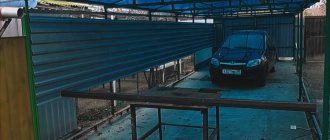
After the preparation has been completed, it is necessary to concrete the supports and the entire site under the future canopy. First of all, four corner posts are installed in the pits; usually the workpiece is cut with a margin of 50 mm in order to be able to align the heads of the supports in the same horizontal plane.
Initially, the polycarbonate roof supports are leveled and fixed with pieces of broken brick, and filled with concrete. Next, the cords are pulled and the remaining four racks are placed along them. If the dimensions of the arched polycarbonate roof are larger than 3x6 m, then it is best to tie the supports at the level of the base with a regular corner.
It is best to entrust the manufacture of roof trusses to an experienced welder; accuracy is required here; any deviation from the plane will lead to collapse of the polycarbonate. The weight of each truss is more than 20 kg, so a team of three people will have to install them on the supports. You can install the sheathing purlins yourself.
Laying polycarbonate is considered the simplest. The sheets are mounted on temperature-compensating washers with a gap at the joints of at least 3 mm, the seam line must be covered with an aluminum cover with a silicone seal.