Almost two years have passed since I moved into our Data City. It's time to report on the work done. The first thing I want to talk about is the simplest transmotor. I decided to defeat the myth about the difficulties in winding transformers, both sound and power. The eyes are afraid, but the hands are doing!
It all started with such a simple machine for 7 rubles 20 kopecks, purchased back in the 80s of the last century.
Features of repair of commutator drives
This type of electric machine is more likely to experience mechanical failures.
For example, brushes worn out or commutator contacts clogged. In such situations, repairs come down to cleaning the contact mechanism or replacing graphite brushes. Testing the electrical part comes down to checking the resistance of the armature winding. In this case, the probes of the device are applied to two adjacent contacts (lamellas) of the collector, after taking readings, measurements are taken further in a circle.
The displayed resistance should be approximately the same (taking into account the instrument error). If a serious deviation is observed, then this indicates that there is an interturn short circuit or open circuit, therefore, rewinding is necessary.
Calculation of product parameters
Before winding a toroidal transformer at home, you will need to calculate its values. To do this you need to know the source data. These include: the output voltage, the outer and inner diameter of the core.
The power of the device is determined by the product of the areas S and Sо, multiplied by the coefficient: P=1.9* S * Sоk.
The cross-sectional area is calculated using the formula: S=h*(Dd)/2, where:
- S - cross-sectional area;
- h - height of the structure;
- D - outer diameter;
- d is the internal diameter.
To calculate the window area, the formula is used: Sok=3.14*d2/4.
The number of turns in the secondary winding is equal to the product W2=U2*50/Sok.
This calculation method can be applied to almost any type of toroidal transformer. But for the calculation of some products there is its own methodology.
Welding device
This type of transformer is characterized by a high output current. The maximum current and voltage are used as input parameters. For example, for a device with a welding current of 200 amperes and a voltage of 50 volts, the calculation is as follows:
1. The power of the transformer is calculated: P = 200 A * 50 V = 1000 W.
2. The window cross-section is calculated: Sok = π * d2/ 4 = 3.14 * 144 / 4 (cm2) ≈ 113 cm².
3. Cross-sectional area: Sc=h * H = 2 cm * 30 cm = 60 cm².
4. Core power: Рс = 2.76 * 113 * 60 (W) ≈ 18712.8 W.
5. Number of turns of the primary winding: W1 = 40 * 220 / 60 = 147 turns.
6. Number of turns for the secondary winding: W2 = 42 * 60 / 60 = 42 turns.
7. The area of the secondary wire is determined based on the highest operating current: Spr = 200 A / (8 A/mm2) ≈ 25 mm².
8. The area of the primary wire is calculated: S1 = 43 A / (8 A/mm2) ≈ 5.4 mm².
This calculation option is applicable not only for welders, but can also be successfully used for other types. As you can see, no difficulties should arise during the calculation.
Current transformer device
It is not difficult to make a current transformer with your own hands, but before making it you will need to perform a calculation. This calculation differs from the generally accepted one due to the design features of the product. It starts with the required value of the secondary current (unit ampere): Iam = Iper / Ivt, where:
• Iper - the value of the primary winding current, multiplied by the number of turns in it;
• Ivt - the number of turns in the secondary winding.
In order to figure out how to correctly perform the calculation, it is easier to consider a practical example of a homemade current device. Let it be necessary to obtain 4 volts at the output of the current device, and limit the current to 5 amperes.
The step-by-step calculation method looks like this:
- Take a ferrite ring, for example 20x12x6 from 2000hM.
- 100 turns of wire are wound. These turns constitute the secondary winding, since the primary is simply one turn of wire passed through ferrite.
- The value of the current in the secondary will be equal to: I/Ktr = 5 / 100 = 0.05 A. where Ktr is the transformation ratio of the transformer (the ratio of the number of primary windings to the secondary).
- The size of the load shunt is calculated according to Ohm's law: R = U/I. It turns out R= 4/0.05 = 80 Ohm.
In this way, calculations can be performed for any required parameters. Regardless of the shape of the current at the input, the voltage at the output of the current device is always bipolar. It is the resistance, not the diode, that is used as the secondary winding shunt. If there is a need for a diode, then a resistor is connected first, and then a diode or diode bridge. In the second case, the resistance is included in the diagonal of the bridge.
Two pulleys are connected by a belt drive
The axles in the winding machine are connected to each other by a system of pulleys of different radii. The pulleys attached to the axles rotate using a belt drive. A belt is used as a belt.
To calculate the pulleys according to the diameter of the winding wire, we accept the following conditions and derive the formula:
— The stacker axis pulley is 100mm;
— A pulley on an axis with a fixed coil (winder) is equal to the thickness of the required wire, multiplied by 100.
For example, for 0.1 mm wire, we use a 10 mm pulley on the axis of the winder. For a diameter of 0.25 wire, a 25 mm pulley.
The error depends on the accuracy of the diameter of the manufactured pulleys and the tension of the belt. If you use a stepper motor with a gear transmission as a drive in the design instead of a belt and precisely cut pulleys, then the error can be brought closer to zero.
Now I’ll tell you how to make a pulley with your own hands at home without turning to a turner. My set of pulleys is made of the same material as the bed of the winding machine. Using a compass, I marked out the required diameters of the pulleys and added a few millimeters on the larger side to machine the groove for the belt to the required size. Holes were drilled along the contour of the markings with a screwdriver and partitions were cut between them. So I collected the required number of blanks for the pulleys. I used an unnecessary “Assistant” meat grinder as a lathe.
I don’t remember exactly, I cut a thread on the meat grinder motor shaft, or it turned out to be suitable, but a pin was screwed through a long bushing nut. A blank with a slightly larger diameter than the required pulley was screwed onto the stud through nuts and washers. The meat grinder was turned on and all the irregularities were rounded to a round shape with a metal hacksaw/file, and a groove (groove) for the belt was machined with a needle file. During the process, the diameters of the homemade pulleys were periodically checked with calipers.
Winding machine operating method
A winding machine is a popular equipment with which transformer single-layer and multilayer cylindrical coils and all kinds of chokes are wound. The winding device evenly distributes the winding wire with a certain tension level. It can be manual or automatic, and works on the following principle:
How does the winding machine work?
- Rotation of the handle sets the winding of the wire or cable onto the coil frame. It serves as the base of the product and is put on a special shaft.
- The wire moves horizontally thanks to the guide element of the stacker.
- The number of turns is determined by special counters. In homemade designs, this role can be played by a bicycle speedometer or a magnetic reed switch sensor.
A mechanically driven winding machine allows you to perform complex winding:
- private;
- toroidal;
- cross.
Manual winding machine with mechanical revolution counter
It operates with the help of an electric motor, which drives the intermediate shaft using a belt drive and three-speed pulleys. The friction clutch plays a big role in this. Thanks to it, the machine operates smoothly, without shocks or wire breaks. A spindle with a fixed frame, on which a coil is placed, starts the counter. The winding machine is adjusted using a screw to any width of the reel frame.
Modern models are equipped with digital equipment. They work through a specially defined program that stores information in a storage device. The value of the length and diameter of the wire allows you to accurately determine the point of intersection of the lines.
Modern winding machines are equipped with special counters
Wire laying device
The process of distributing long material is carried out by three plates that are connected to each other. A 6 mm hole is drilled in the upper part of the structure being created. It is used to install the screw:
- Bushings with a diameter and length of 20 mm are mounted in the plates.
- The outer elements are connected by gluing the leather gutter. They are required to align and tension the reel.
- A steel rod with threads is attached to the top. It is designed to hold plates together.
- You can simplify the process by installing a folding bracket.
Wire laying device
A homemade winding machine is characterized by high efficiency. The winding device is quite simple to make even using simple materials and tools.
Components of a winding machine and its operating principle
The elements of the winding machine were assembled slowly. Almost everything was taken from old Soviet film equipment. Moving parts: handle, axle studs, guide roller - everything is equipped with bearings. Studs, nuts, washers and angles were purchased at a hardware store. I only had to spend money on studs, long nuts and angles. Otherwise, everything is made from available materials.
To accurately select the wire winding density, a set of several pulleys is threaded onto the stacker pin. So, in the case of loose winding, it was possible to move the belt one size and adjust the speed of rotation of the axes. During the process of winding the wire, the belt is twisted depending on the direction of the winding stroke according to the figure-of-eight shape or the direct position of the belt. You should make a couple of dozen test turns to correctly adjust the pulleys to the diameter of the wire.
A base is made from wood or other material in the shape of the inside of the transformer coil and is fixed to the stud with wing nuts. You can also make universal holding corners to secure the coil. A demonstration of the operation of the winding machine is shown in the video:
↑ Mechanics
First you need to think about the mechanical part. What can you think, the carriage from the printer moves perfectly, why not use it? Cutting out everything unnecessary and leaving only the frame with the axle and carriage. Everything is fine, but it is driven by a commutator motor, and I can’t control it through an encoder strip and PWM, I need to come up with something on a stepper motor.
I look at the scanner and it’s a miracle, there’s a stepper motor moving the lamp, and there’s also a gearbox.
We take this gearbox with a motor and attach it to the printer bed. Having recalculated the distance the carriage will travel in 1 step of the engine, I set the constant A = 0.02 mm. As the wire manager itself, I used a disk from an old hard drive, having previously cut out the j-sectors from it so that it would fit properly on the carriage. The wire will pass through a system of rollers, which were kindly unscrewed from the scanner and soldered to the hard drive.
That's it, the wire manager is ready.
Do-it-yourself transformer winding machine
Very often, when creating electronic homemade products, you have to wind and rewind various transformers and coils. A good assistant in this difficult and painstaking task can be an easy-to-manufacture and reliable homemade winding machine for pulse transformers from computer power supplies and conventional transformers with a “W” shaped magnetic core. The design of the winding machine is very simple to manufacture, even a novice turner can do it. The machine consists of a shaft mounted on a rotation support. On the right side there is a handle for rotating the shaft. On the shaft from left to right there is a clamping device, left and right cones for reliable fastening of transformers.
This picture shows a drawing for making a winding machine with your own hands. The machine is designed for winding pulse transformers from computer power supplies and “W” shaped transformers. If you are going to wind something very small or too large then you need to scale the drawing to suit your needs. Well, if you are satisfied with the size of the machine, feel free to take the drawing and go to a familiar turner. - A good turner will make a winding machine in three hours... - Let him do it. Oh, and don't forget to bring some currency lathe with you. All work must be paid.
Drawing of a winding machine for winding pulse transformers
The machine is equipped with an electronic revolution counter. Which I purchased from a very famous Chinese online store for only $7.5. Perhaps it’s not expensive... For this money, the meter is equipped with a reed switch sensor, a mounting plate for the reed switch sensor and a small neodymium magnet! There are two oval buttons on the front panel of the meter. The left “Pause” button turns on the device and saves the meter readings, the “Reset” button resets the device readings. The device is powered by just one 1.5V AA AA battery, located on the rear panel of the revolution counter under a plastic cover. There are also connectors for connecting a reed sensor and an additional “Reset” button. Read the review of the revolution counter in this article.
I screwed the reed sensor to the aluminum stand using a mounting plate. A neodymium magnet was attached to the handle. For proper operation of the device, it is necessary to establish a gap between the reed sensor and the neodymium magnet of no more than five millimeters. Each passage of the neodymium magnet over the reed sensor is counted by the revolution counter as one turn.
How to use a transformer winding machine?
And so, a turner I knew made all the parts of the machine in three hours. You assembled the winding machine with your own hands, carefully lubricated all the rotating parts, and installed a winding counter. Now you can start winding the transformers. Unscrew the M5 screw on the clamping device, remove it and the left clamping cone. We put the transformer frame on the shaft and put on the left cone with a clamping device. Use a flat screwdriver to fix the M5 screw on the clamping device, then tighten the frame with two nuts. In this case, the main thing is not to overtighten, otherwise you will split the frame. We turn on the turns counter and, if necessary, reset the device readings to zero.
We clean the end of the wire from the varnish with a knife and screw it to the frame stamp from the transformer. We guide the wire with our left hand, and rotate the handle with our right hand. After a few minutes of training, the wire will lie in even layers. To avoid breakdown, each layer of wire is insulated with several layers of ordinary tape. Don't forget to watch the meter readings.
Friends, I wish you good luck and good mood! See you in new articles!
↑ Total
I have already tested the machine in winding with 0.315 wire (I wound an output transformer for a guitar amplifier on a frame from OSM-0.16). I'm pleased with the quality of the winding and the work.
I hope my article helps someone. With the development of automation, I am thinking about adding a motor to the main axis and updating the software to control the second stepper motor. Automation is the engine of laziness!
↑ Algorithm of my program
I will describe the algorithm of the program as I saw it for myself. We turn on the controller and the seven-segment indicator shows “0.00” zeros. Using the “+1” and “-1” buttons, set the value of the wire diameter (for example, 0.31) and press the “START” button. The controller, based on the above constant “A = 0.02”, recalculates how many pulses it needs to send to the stepper motor driver to move it a distance of 0.31 mm. Those. 0.31/0.02 = 15.5 pulses. Since the number of pulses must be an integer, the controller produces 16 pulses (or 15). There is an error, where without it.
We press the “START” button, a small square lights up on the very first indicator and the program moves to the next stage of work, where the controller waits for a signal from the sensor, which will be on the axis with the coil, to allow it to issue a packet of pulses for the stepper motor. Here he receives an impulse and the MK issues a packet of impulses. The wire layer carriage moves and waits for the next enable pulse.
If during the work you need to “adjust” the diameter of the wire and return to the first part of the program
, you need to press “START”, the square will disappear and you can change the value of the wire diameter. One note: in order for the controller to respond to the “START” button, the sensor disk on the main axis must be on the black segment, i.e. the controller must receive a “log” level from the sensor. 1".
I haven’t learned how to work with interruptions yet and did the best I can. I drew the sensor disk into 4 parts and painted the opposite segments with black varnish, in a checkerboard pattern. Since there will be 2 black sectors on the disk, the controller will respond to every 180 degrees of rotation of the axis, and accordingly will move the carriage by ½ of the wire diameter for every 180 degrees. In this case, the minimum winding pitch (in my case) = 0.04 mm. The program runs under an internal clock with a frequency of 1 MHz.
Device and principle of operation.
Feeding unit.
The feeding unit is designed to attach a reel of wire of various sizes to it, and provide tension on the wire. It includes a bobbin fastening mechanism and a shaft braking mechanism.
Figure 2. Feeder unit.
Braking.
Without braking the feed reel, the winding of the wire on the frames will be loose and high-quality winding will not work. Felt tape “2” slows down drum “1”. Turning the lever “3” tightens the spring “4” - adjusting the braking force. For different wire thicknesses, its own braking is adjusted. Off-the-shelf VCR parts are used here.
Figure 3. Braking mechanism.
Bobbin centering.
The small dimensions of the machine and the location in close proximity of the winding reel and the feed reel with wire required the introduction of an additional mechanism for centering the feed reel.
Figure 4, 5. Centering mechanism.
When winding the coil, the wire from the reel acts on the shutter “5”, made in the form of a “fork” and the stepper motor “3”, through a gearbox with division 6 and a toothed belt, along roller guides “4”, automatically moves the reel in the desired direction. Thus, the wire is always in the center, see Fig. 4, Fig. 5:
Figure 6. Sensors, rear view.
Composition and design of sensors.
19. Optical sensors for the bobbin centering mechanism. 5. A curtain covering the sensors of the reel centering mechanism. 20. Curtains covering the positioner direction switching sensors. 21. Optical sensors for switching the direction of the positioner.
Positioner.
Curtains “20” fig. 6 — the winding limit is set. The stepper motor moves the stacker mechanism until the curtain blocks one of the sensors “21” fig. 6, after which the laying direction changes. You can change the laying direction at any time using buttons “1” fig. 7.
Figure 7. Stacker.
Rotation speed of stepper motor “9” fig. 7, synchronized using sensor “10”, “11” Fig. 8, with the rotation of the wound coil and depends on the diameter of the wire set in the menu. The wire diameter can be set to 0.02 – 0.4mm. Using knob “8” fig. 7, you can move the entire positioner to the side without changing the winding boundaries. In this way, it is possible to wind another section in multi-section frames.
Figure 8. Optosensor.
Composition of the positioner and opto-sensor (Fig. 7-8).
1. Buttons for manually switching the laying direction. 2. LEDs for laying direction. 3. Curtains covering the positioner direction switching sensors. 4. Linear bearing. 5. Caprolon nut. 6. Lead screw. Diameter 8mm, thread pitch 1.25mm. 7. Ball furniture guides. 8. Handle for moving the positioner to another section when winding sectional windings. 9. Stepper motor. 10. Optical timing sensor. 11. Disk covering the synchronization sensor. 18 slots.
Receiving node.
Figure 9. Receiving node.
Figure 10, 11. Receiving unit.
1. Turn counter. 2. Commutator high-speed motor. 3. Reducer gear. 4. “Counter reset” button. 5. Speed adjustment. 6. “Start winding” switch. 7. Fastening of the winding reel.
The rotation of the wound coil is produced by a high-speed commutator motor through a gearbox. The gearbox consists of three gears with a total pitch of 18. This provides the necessary torque at low speeds. The motor speed is adjusted by changing the supply voltage.
Operating principle of the machine
It is not difficult to work on the designed machine. The technological process requires certain actions:
- The upper shaft is prepared for work: the pulley is removed, the required length of the coil frame is set, and the right and left disks are installed.
- A fastener is inserted into the hole in the upper shaft, centered and the frame is clamped with a special nut.
- The required pulley for the primary winding is mounted on the feed shaft.
- A stacker is installed opposite the reel frame.
- The belt is placed on the pulleys in a ring or figure eight, depending on the type of installation.
- The metal wire is inserted under the additional shaft, placed in the groove, and secured.
- The wire tension is adjusted using clamps located at the top of the stacker.
- The wire should be wound tightly around the base of the coil.
- The numerical value “1+1” is recorded on the calculator.
- Each revolution of the shaft adds a given count.
- If the turns need to be rewinded, press “–1” on the computing device.
- When the wire reaches the opposite part of the frame, use a collet clamp to change the position of the belt.
For different thicknesses of metal wire, the pulley is correlated with the winding pitch.
Add a link to a discussion of the article on the forum
RadioKot >Laboratory >Amateur Radio Technologies >
| Article tags: | Add a tag |
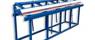
Simple tabletop winding machine.
Author: N. Filenko aka UA9XBI Published 09.11.2007
The lack of the necessary transformer made us think about creating a winding machine. Of course, you could order a transformer at the factory or wind it yourself using friends’ equipment, but who would refuse to have in their arsenal something so necessary as a convenient machine for winding transformers, coils and chokes? The machine turned out to be simple and at the same time functional. Front and top view.
It allows you to wind windings on round hollow frames with an internal diameter of 10 mm, as well as on square or rectangular frames with an internal size of 10x10 mm. The maximum winding length is 180 -200 mm. The maximum diameter (diagonal of the rectangular frame) is 200 mm. Winding can be done manually with a wire with a diameter of up to 3.2 mm, in the winding mode with wire from 0.31 to 2.0 mm. winding involves winding and laying a layer of wire synchronously with winding, followed by manual laying of the insulation layer and changing the direction of laying the wire. On round mandrels with manual laying, even tubes with a diameter of up to 6 mm can be wound. For laying wires of different diameters, a set of interchangeable pulleys is provided, allowing you to select 27 different winding steps in the range of 0.31 - 1.0 mm or 54 winding steps in the range of 0.31 - 3.2 mm. The machine itself easily fits on a regular kitchen stool and, due to its large weight, does not require additional fastening.
Principle of operation.
Simple as hell. The shaft on which the transformer frame is mounted is kinematically connected to the shaft along which the wire handler moves. The wire manager has a sleeve with a thread inside. When the shaft rotates, the sleeve moves and moves the wire guide along with it. The rotation speed of the shaft is determined by the diameters of the pulleys installed on the upper and lower shafts, and the speed of movement of the sleeve is also determined by the thread pitch of the stacker shaft. A set of 3 triple pulleys allows for up to 54 wire spacing combinations. The direction of laying is changed by rearranging the belt connecting the pulleys. The rotation of the shaft with the frame can be done manually, or you can use an electric drill as a drive.
DETAILS:
All dimensions are as in the original. bed
The machine bed is welded from steel sheets. The base of the frame is chosen to be 15 mm thick, the sides - 6 mm thick. The choice is determined primarily by the stability of the machine (the heavier the better). Before welding, the sidewalls of the frame are folded together and holes are drilled simultaneously in both sidewalls. After this, the frames are installed on the base and welded to it. Bronze bushings are inserted into the upper and middle holes of the sidewalls, and bearings into the lower ones. The bearings are taken from an old 5 inch drive. The bearings and bushings on the outside of the sidewalls are secured with covers to prevent movement.
Shafts.
The upper shaft on which the reel frame is attached is made of a rod with a diameter of 12 mm. In this design, all shafts are made from shafts of suitable diameter from used dot matrix printers, they are made of good steel, hardened, chrome-plated or ground.
The middle shaft on which the wire feeder rests is also made of a rod with a diameter of 12 mm. It is advisable to polish the shaft.
The choice of the diameter of the lower shaft - the feeder - was determined by the need to have a thread pitch of 1 mm, and there was only one suitable 10x1.0 hole. It is advisable (for greater reliability) to make this shaft also with a diameter of 12 mm.
Stacker bushing.
Diameter 20 mm, length 20 mm, internal thread is the same as on the lower shaft M12x1.0 (in the original - M10x1.0)
Pulleys
The pulleys are made of triple ones, i.e. 3 grooves of different diameters in one block. The diameters are selected to best cover the required range of wire cross-sections
Machined from steel, the combination of pulleys allows for 54 different wire winding pitches. The width of the groove for the belt is selected based on the existing belts, in this particular case 6 mm. Please note: the total thickness of the pulleys should be no more than 20 mm. If the thickness of the pulleys is greater, it is necessary to increase the length of the left shanks of the lower and upper shaft (the diameter of which is 8 mm, length 50 mm). If necessary, single pulleys of the corresponding diameters can be made. The selected pulley diameters allow the wire to be wound in 54 different pitches.
Step table.
The rows indicate the diameters of the driving pulleys, the columns indicate the diameters of the driven pulleys. In the cells of the table there is a wire winding sword.
| 25 | 30 | 35 | 35 | 45 | 55 | 60 | 70 | 80 | |
| 25 | * | * | * | 0,71 | 0,555 | 0,454 | 0,416 | 0,357 | 0,31 |
| 30 | * | * | * | 0,857 | 0,666 | 0,545 | 0,5 | 0,428 | 0,375 |
| 35 | * | * | * | 1,0 | 0,77 | 0,634 | 0,583 | 0,5 | 0,437 |
| 35 | 1,4 | 1,166 | 1,0 | * | * | * | 0,583 | 0,5 | 0,4375 |
| 45 | 1,8 | 1,5 | 1,28 | * | * | * | 0,75 | 0,642 | 0,56 |
| 55 | 2,2 | 1,833 | 1,57 | * | * | * | 0,91 | 0,78 | 0,6875 |
| 60 | 2,4 | 2,0 | 1,71 | 1,71 | 1,33 | 1,09 | * | * | * |
| 70 | 2,8 | 2,33 | 2,0 | 2,0 | 1,55 | 1,27 | * | * | * |
| 80 | 3,2 | 2,66 | 2,08 | 2,08 | 1,77 | 1,45 | * | * | * |
This table is only indicative, since it depends on the manufacturing accuracy of the pulleys, the diameter of the belt and the thread pitch on the lower (feed) shaft. After manufacturing the entire machine, it is necessary to clarify the resulting relationships using the test winding method and draw up a similar table. Inaccuracy in manufacturing will not affect performance; other diameter ratios will lead to different winding steps. But a large number of combinations will allow you to choose the right step in any case. If you need to wind with a thinner wire, you can make another triple pulley with diameters of, for example, 12, 16 and 20 mm. The presence of such a pulley will further expand the range of wires used (starting from a diameter of 0.15 mm)
Wire handler.
Layer plate drawing.
Made from 3 plates connected to each other with M4 screws. Hole diameter 20 mm. A hole in the upper part with a diameter of 6 mm for the tension adjustment screw. The inner plate is steel; a steel sleeve with a diameter of 20 mm, a length of 20 mm and with an internal thread of 12x1.0 is welded into the lower hole. A fluoroplastic bushing with an outer diameter of 20 mm and an inner diameter of 12.5 mm is inserted into the upper hole. The length of the bushing is 20 mm. The plates are tightened together with 2 M4 screws; the holes for them are not shown in the figure. A groove made of leather 1.8-2 mm thick is glued into the groove between the outer plates; it helps straighten and tension the wire. To adjust the tension, a screw or a mini-cub is installed in the upper part of the stacker, tightening the upper part of the outer plates depending on the diameter of the wire and the required tension.. A folding bracket for a reel of wire is installed in the rear of the frame, an optional but convenient thing.
Drive unit.
A large diameter gear is used as a drive, to which a handle is riveted. On the right side of the frame (in place) there is a fixation and auxiliary drive unit, which is a shaft with a gear mounted on a separate bracket with a collet clamp and a protruding axis. The axis can be secured in the chuck of a cordless screwdriver or electric drill and thus become an electric drive. When winding a thick wire, you can attach a handle to the axis, then winding even a thick tube will be easier. The collet clamp allows you to reliably fix the shaft with the winding reel, if for some reason you have to interrupt the winding for a long time.
Turn counter.
A magnet is attached to the upper shaft gear, and on the right side there is a reed switch, the terminals of which are connected to the contacts of the calculator button. All other small parts and components are installed in place and made from whatever God sends. The last photo shows that the coil of wire is placed on a separate shaft. the shaft is mounted on 2 levers that can be lifted up and then folded inside the machine. This is done so that the machine does not take up much space during its inactivity.
Working on the machine.
Although it is already clear what is being done and how, I will describe the procedure. The slight complexity of installing frames and the apparent difficulty of changing the laying direction are compensated by the simplicity of the machine. Remove the upper pulley, push the upper shaft to the right to the length required for installing the frame. Place the right disk on the shaft, then the coil mandrel, and put the coil or transformer frame on the mandrel. Install the left disk, screw on the nut and insert the shaft into the left bushing. Reinstall and secure the upper pulley (corresponding to the table for winding the primary winding). Insert a cotter pin or nail into the hole on the upper shaft, center the frame on the mandrel and tighten the frame with the mandrel using a nut. Install the required pulley (for winding the primary winding) on the feed shaft. Rotate the feed shaft pulley to install the stacker against the right or left neck of the reel frame. Place the belt on the pulleys. If the wire is laid from left to right, the belt is put on, if the wire needs to be laid from right to left, the belt is put on.
The wire is threaded under the additional shaft, then laid from bottom to top in the leather groove of the handler and secured to the frame. The clamps on the top of the stacker adjust the tension of the wire so that it is tightly wound around the frame. On the calculator press 1 + 1. Now, with each revolution of the shaft with the frame, the calculator will add 1, that is, it will count the turns of the wire. If you need to unwind several turns, press - 1 and with each revolution of the shaft, the calculator readings will decrease by 1. While winding the wire, monitor the laying of the turns, adjusting the turns on the frame if necessary. When the wire reaches the opposite cheek of the frame, clamp the collet clamp and change the position of the belt from to or vice versa. After releasing the collet, place release paper under the wire and continue winding. If you need to change the thickness of the wire, select the pulley ratio for the required winding pitch... Well, that's all. I apologize for the low quality of the photos, but I hope that everything will become clear to you from the photos and drawings provided.
As usual, we put the questions here.
| What do you think of this article? | Did this device work for you? | |
| 42 | 3 | 1 |
| 3 | 1 |
Manufacturing of turns counter
To determine the number of wound turns on the machine, a special counter is needed. In a homemade machine, the device is made like this:
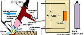
Counter for winding machine - diagram
- An electromagnet is attached to the upper shaft.
- The sealed contact is located on one of the sidewalls.
- The output contacts of the reed switch are connected to the calculator in the place where the “=” button is located.
- The coil with the wire is placed separately - on another shaft with levers that lift the device up and fold it inside the machine.
Thanks to these elements, the equipment becomes compact and does not take up much space.
Necessary materials and equipment for manufacturing
The main element of almost any structure can be called the frame. It is made by joining all the elements together by welding. The design features are as follows:
- A homemade winding machine should not withstand heavy loads. Therefore, holes are drilled in individual elements and then welded to the base.
- Bushings are mounted in the previously created holes, and bearings are placed in the lower ones.
- On the outside of the structure, the fastening elements are covered with covers.
- The upper shaft should have a diameter of 12 mm. It is designed to secure the reel.
- The middle one is designed to distribute the thread around the drum. Before using the mechanism, this element is polished.
- The lower shaft is intended for feeding long material. Its size can vary over a wide range.
Homemade winding machine
Winding machine manufacturing
The winding device can be made independently. It is recommended to use three-stage pulleys, which are machined from hardened steel.
The device of a homemade winding machine
In industrial settings, special fixtures are used to mass produce various types of electrical coils and transformers. The production of similar products allows you to invest financial resources in high-speed, automatic equipment to increase the number of products produced.
When working with your own hands when repairing, restoring, creating new coils or transformers, there is no need to fully automate the rewinding process, but the method of manually laying each turn of wire does not suit all craftsmen. Therefore, the practice of creating your own models arose.
The simplest option is a do-it-yourself manual winding machine, which is equipped with an adjustable stacker and a winding counter.
When creating it, you should pay attention to only a few conditional requirements:
- simplicity of design;
- use of improvised materials;
- possibility of winding coils of different sizes and configurations.
The device of the simplest homemade winding machine for transformers
An example of such a machine made by hand is this design, which works on the principle of a well gate:
- base with two vertical posts made of wood or plywood;
- a horizontal axis mounted on stands made of thick wire, one end of which is curved in the shape of a handle for rotation;
- two tubes mounted on the axle, on one of which there is a wooden block, which is fixed with a metal pin and has a wedge for reliable fixation on the rotating axle;
- a coil counter (bicycle odometer), which is connected to the free end of the axle through a dense rubber tube or a coiled spring of a suitable cross-section.
The principle of operation of such a device is based on placing the transformer frame on the axis of the device, and rotating the gate with your own hands with manual control of the density of the wire laying and visual control by counting the turns. to menu
Winding of toroidal transformers
The widespread use of toroidal transformers in household appliances and devices providing low-voltage lighting creates the need for a machine, or rather, a device that will help wind wire on a frame of a round closed shape.
In industrial conditions, special ring machines are used for high-quality winding of toroidal transformers. At home, you have to wind it by hand for a long time and without a guarantee of high-quality, even laying of the wire.
A device in the form of a shuttle, which works on the principle of a sewing needle, somewhat facilitates the work of winding toroidal transformers, but not to an sufficient extent.
Winding machine for toroidal transformers
To create a more productive device for winding toroidal transformers, you will need a bicycle wheel rim. It is secured to the wall with a pin and has a rubber ring to secure the wire.
Since the rim is solid, in order to put the frames of toroidal transformers on it, it will need to be cut and then fastened with collapsible plates.
Winding toroidal coils using this device occurs as follows:
- a reel prepared for winding is put on the disconnected rim;
- the rim is fastened (connected) with plates so that it is a solid circle;
- wind the required amount of wire around it;
- connect the end of the wire to a coil freely moving along the rim;
- They begin to move the coil along the rim in complete circles, due to which the wire itself is laid on the transformer frame.
When performing such almost manual winding, it is necessary to monitor the wire tension and the density of the turns.
data-ad-client=»ca-pub-8514915293567855″ data-ad-slot=»5929285318″>
The bicycle wheel rim is only suitable for large reels. The same winding principle can be applied for small toroidal transformers using any flat ring of suitable dimensions. to menu
This is interesting: Hydraulic pipe benders - types, videos, photos
Two pulleys are connected by a belt drive
Making blades for a wind generator with your own hands
The axles in the winding machine are connected to each other by a system of pulleys of different radii. The pulleys attached to the axles rotate using a belt drive. A belt is used as a belt.
— The stacker axis pulley is 100mm;
— A pulley on an axis with a fixed coil (winder) is equal to the thickness of the required wire, multiplied by 100.
For example, for 0.1 mm wire, we use a 10 mm pulley on the axis of the winder. For a diameter of 0.25 wire, a 25 mm pulley.
The error depends on the accuracy of the diameter of the manufactured pulleys and the tension of the belt. If you use a stepper motor with a gear transmission as a drive in the design instead of a belt and precisely cut pulleys, then the error can be brought closer to zero.
Now I’ll tell you how to make a pulley with your own hands at home without turning to a turner. My set of pulleys is made of the same material as the bed of the winding machine. Using a compass, I marked out the required diameters of the pulleys and added a few millimeters on the larger side to machine the groove for the belt to the required size. Holes were drilled along the contour of the markings with a screwdriver and partitions were cut between them. So I collected the required number of blanks for the pulleys. I used an unnecessary “Assistant” meat grinder as a lathe.
I don’t remember exactly, I cut a thread on the meat grinder motor shaft, or it turned out to be suitable, but a pin was screwed through a long bushing nut. A blank with a slightly larger diameter than the required pulley was screwed onto the stud through nuts and washers. The meat grinder was turned on and all the irregularities were rounded to a round shape with a metal hacksaw/file, and a groove (groove) for the belt was machined with a needle file. During the process, the diameters of the homemade pulleys were periodically checked with calipers.
Winding machine on Arduino
Sometimes in amateur radio practice it becomes necessary to wind a large number of turns of wire to create transformers, chokes, coils and similar winding products. If we are talking about a hundred turns there are no special problems; it is wound using simple mechanical devices. But when you need to wind several thousand turns, and even turn after turn, then you think about automating this very tedious process.
The device in question is an automatic winding machine with a winding stacker and a process indication on a symbolic LCD screen. The intelligent core of the device is the familiar ATmega328P microcontroller, located on the Chinese version of the Arduino UNO board. The controller, through a CNC Shield (CNC expansion board), controls the power part of the device, consisting of two stepper motor drivers (SM) based on the DRV8825 chip and two stepper motors 17HS3401 and 17HS4401 (full revolution 200 steps). The HMI consists of a KY-040 rotary encoder module and a 16x2 character display with an HD44780 controller and an I2C bus communication module on a PCF8574A port expander. The circuit receives power from a 220AC-12DC 60W switching power supply.
The microcontroller uses drivers “Z” and “A”; on the CNC Shield, to connect driver “A” to pins 12 and 13 of the Arduino, jumpers D12-A.STP and D13-A.DIR must be installed. We select the DRV8825 operating mode with a microstep of 1/16 by installing jumpers M2 on the board, this means that for one step of the SD (1.8°) it is necessary to apply 16 edges of the STP signal. The installation of DRV8825 modules must be done as shown below.
After installing the SD drivers, it is necessary to set the current limit. When a 12V voltage is connected to the CNC Shield board, but without electric motors, you need to rotate the trimming resistor to set the limit values. We control the current value with a multimeter and by rotating the trimmer with a screwdriver, we achieve voltage values for driver “Z” of 0.68V and 0.52V for driver “A”. These values are directly related to the rated current of the motor. For 17HS4401 In = 1.7A, and for 17HS3401 In = 1.3A. The voltage value in a mode that is gentle for the motor is calculated using the formula Vref = 0.8*(In / 2).
We connect the I2C 1602 LCD to the corresponding pins SCL, SDA, 5V, GND of the expansion board. On the encoder module we add a pull-up resistor R1 10k if it is not there. To eliminate contact bounce, it is necessary to assemble a hardware suppression circuit; it can be designed as a module that complements the KY-040 module as shown below. Low-pass filters on R4-6 and C1-3 eliminate bounce, and Schmitt triggers MC 74НС14N restore the leading and falling edges of the signal.
To connect the encoder to the Arduino, we connect pins X.STEP and CLK, Y.STEP and SW, X.DIR and DT as well as GND and +5V with the corresponding pins of the board.
The mechanical part of the winding machine consists of six racks screwed to plexiglass. The stands are printed with plastic on a 3D printer, but if they have the proper straightness, they can be made in other ways and from other materials. The main shaft (M6 pin) is driven by SD 4401 and the winding frame is located on it. Next are two stacker stands with a shaft with a diameter of 6 mm and an M4 pin (thread pitch 0.7 mm) on the SD 3401 shaft. Rotation of the motor leads to linear movement of the stacker, while one step of the SD gives movement L = thread pitch / steps per revolution = 0.7 /200 = 0.0035mm. The last two posts hold the feed reel. Pressing the rubber washer against the bearing ensures tension in the wire during winding.
The program for ATmega328P is written in the Arduino IDE development environment in C++. To successfully compile the code, you must have the LiquidCrystal_I2C library installed.
From the main menu you can get to the submenu for controlling the position of stepper motors POS CONTROL; this is necessary to set the initial position of the main shaft and stacker. The AUTOWINDING submenu is for entering automatic winding values. Work with the encoder button, as well as with the encoder itself and the stepper motor drivers, is carried out through interrupts.