If the calculation is not carried out, the permissible stress values are not calculated automatically - try enabling JavaScript in your browser. Instructions here
Notes: 1) Calculation of the pipe wall thickness is carried out according to the RD 10-249-98 method. 2) The values of the fields highlighted in color are filled in automatically from the internal database; if desired, you can enter your own values. 3) The values of the fields highlighted in color are filled in automatically based on the calculation results. 4) Allowable stresses are determined in accordance with RD 10-249-98. 5) For steel grades X10CrMoVNb9 and P265GH, the permissible stresses are taken according to EN data. The permissible stresses of X10CrMoVNb9 steel are determined at a temperature value of more than 500 * C 6) The minus tolerance for wall thickness is filled in automatically. Up to outer diameter 114 – 10% of the thickness, more – 5% (TU 14-3R-55). 7) The online program is working in test mode! Please leave your comments and suggestions in the reviews. IMPORTANT: By using this service you confirm that you are using the program at your own risk and solely for informational purposes. The resource administration is not responsible for the calculation results. The purpose of the program is preliminary calculations for subsequent independent calculations in accordance with the current Standards for strength calculations.
Number of visitors performing On-line calculations:
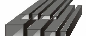
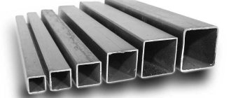
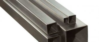
One of the most popular products in construction is steel pipe. For example, VGP pipe VGP DN 15x2.8mm 6m can be used for communications, and square-section products are used as supports. In the latter case, during design it is necessary to correctly determine the load-bearing capacity of a metal square steel pipe.
What is the maximum load on a steel pipe support?
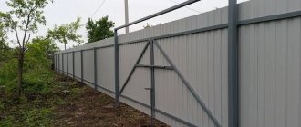
In many load-bearing structures, the pipe plays the role of an element, without which it is impossible to build a frame. In addition, the products are convenient to use when constructing various partitions. An important advantage of the product is that it is suitable for both temporary and permanent use. That is why pipes are often used as reliable supports for equipment and auxiliary equipment.
The operation of the pipe as a load-bearing element is explained by the fact that this product is different:
- high compressive and tensile strength;
- immunity to vibrations;
- sufficient elasticity;
- suitability for repeated use;
- affordable price;
- ease of installation.
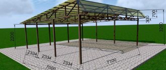
To achieve such benefits from use, it is necessary to correctly determine the load-bearing capacity, that is, calculate the load that a steel pipe support for a canopy, overhead line, equipment, etc. can withstand.
Methods for deforming profile pipes
In order to give the greenhouse a characteristic semicircular shape at the top, the structural elements must not be straight, but curved with a certain radius.
It is no secret that it will not be possible to bend a rolled profile by forcefully bringing its two ends together, since the walls on the inside will wrinkle. However, there are many ways to correctly deform profiled metal.
Among the things that can be applied in a home workshop, I would like to note the following:
- deformation using a pipe bender;
- deformation using welded tacks;
- deformation through cutting and subsequent welding.
Using a special tool
The instructions for bending a pipe using a pipe bender are similar, regardless of the modification of the tool.
Stages of working with hydraulic tools
Let's look at the stages listed in the diagram using the example of operating a homemade hydraulic pipe bender.
- At the initial stage, we cut the pipes into pieces of the required length
Tool rollers in neutral position
- The tool rollers are set to a neutral position, that is, no pressure is applied to the workpiece;
Adjusting the rollers to apply load to the workpiece
- Then, using a jack, the rollers are moved so that the necessary pressure is applied to the workpiece;
Rolling the workpiece
- Using a manual winch, the workpiece is rolled several times from side to side along the pressure rollers;
- As the workpiece bends, the rollers are additionally pressed with a jack;
- The workpiece is again rolled several times along the pressure rollers;
The required radius is almost achieved
- The listed steps are repeated exactly until the workpiece takes on the required bend radius;
- After the required configuration of the workpiece is obtained, the pressure rollers move away and the product is released.
Finished goods
A similar method is used when working with a manual pipe bender, where, unlike hydraulics, the rollers are pressed by tightening the screw.
Recommendations for bending profile pipes using a hydraulic pipe bender
Do not apply excessive pressure to the rollers at one time. As a result, you will not deform the workpiece and it will be easier to turn the gate.
Use rollers of a suitable configuration, that is, the width of the rollers should correspond to the cross-sectional width of the pipes. In this case, the bending will be more accurate, and the workpiece will not move from side to side when passing through the machine.
Before starting bending, I recommend preparing a radius template or measuring the distance that should be between the ends of a correctly bent pipe. Subsequently, knowing the distance or having a template, it will be easier to assess the readiness of the bend without removing the workpiece from the tool.
How to bend a profile pipe without a special machine
The price of a ready-made pipe bender is high, but this tool can be made with your own hands. On the other hand, this tool may simply not be at hand at the most necessary moment, so what should you do in such a situation?
I propose, as an example, to consider a unique technology for deforming rolled profiles for assembling a polycarbonate canopy.
Why a canopy? The fact is that the method I want to talk about has restrictions on the bend radius and it will not be possible to prepare components for the greenhouse, but bending the blanks for assembling the canopy trusses is easy.
The diagram shows how to do without a pipe bender
Let's look at the stages listed in the diagram in more detail.
Future farm foundation
- At the initial stage, we prepare rolled profiles with a rectangular cross-section for the base of the truss;
Marking for jumpers
- We measure the workpiece in length and, in accordance with the measurements, divide it into 6 equal fragments, as shown in the photo;
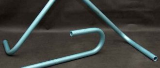
- We prepare vertical supports;
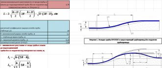
Universal calculation of jumper heights
In the photo you can see the calculation and reduction factor for the length of the supports. This is a very important point, since cutting the supports in accordance with the above calculations allows you to bend any pipes without fear of crushing their walls.
Jumpers are welded
- We weld the vertical supports to the base of the truss according to the previously marked marks;
We try on the profile from the end with an overlap of at least 10 cm
- We prepare a section of profile pipe that is to be bent;
Bend to one of the ends of the base
- We apply the workpiece to the vertical supports at both ends of the base of the truss;
We weld the end by welding
- We weld the pipe to the first support;
We weld the second end
- Then we weld the pipe to the last support, gradually bending it, leaning on it with body weight.
Recommendations for bending:
- The beam to which the arc will be tacked must be securely fastened, since working on a moving beam will not ensure bending accuracy;
- The beam on which the supports will be welded must be made of a profile pipe with a cross-section of at least 50 by 50 mm, taking into account the bending of a pipe with a cross-section of 20 by 20 mm;
For ease of operation, the pipe can be temporarily tied
- If you work alone, tie one of the ends of the bent workpiece with a rope while we direct it to the next support;
- We weld the vertical posts to the beam at an angle of 90°;
- The coefficients used to calculate the length of the vertical posts are relevant, regardless of the size of the finished structure;
The jumpers have been removed, but the deformation radius is still the same
- The assembled structure is so strong that it can subsequently work without vertical posts only due to end tacks.
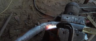
Deformation of a profile pipe by cutting with a grinder
Finally, I suggest you familiarize yourself with a simple method of deformation, which is relevant when working with large-section profiles.
To work, we will need an angle grinder (grinder) or a miter saw, a welding machine and a measuring tool.
The instructions for working with the profile pipe are as follows:
- We mark the location of the cuts on one of the walls of the pipe (after bending, this wall will be external);
Marking for cutting
- From the marks made, we draw triangles with an angle so that when folded at the cut sites, the product takes the desired shape and the desired radius of curvature is obtained;
Cutting made according to markings
- Using the marks made, we saw the workpiece and remove unnecessary pieces of metal;
Deformation with the desired radius
- The workpiece is bent so that the edges of the cuts meet;
Welding joints
- The edges of the cuts are welded.
The method is good in its simplicity, but you need to take into account that the bend line will be broken. Therefore, this solution is not suitable for the manufacture of canopies, where the sheathing is pricked with a solid sheet of polycarbonate.
Properties of bendable metal
Metal has its own point of resistance, both maximum and minimum.
Maximum load on the structure leads to deformations, unnecessary bends and even breaks. When making calculations, we pay attention to the type of pipe, cross-section, dimensions, density, and general characteristics. Thanks to this data, it is known how the material will behave under the influence of environmental factors.
We take into account that when pressure is applied to the transverse part of the pipe, stress arises even at points distant from the neutral axis. The zone of most shear stress will be the one located near the neutral axis.
During bending, the inner layers in the bent corners are compressed and reduced in size, and the outer layers are stretched and lengthened, but the middle layers retain their original dimensions after the end of the process.
How to make the right calculations
Calculation of a profile pipe for deflection is the determination of the degree of maximum stress at a specific point on the pipe.
Each material has normal stress indicators. They do not affect the product itself. To make the calculations correctly, you must apply a special formula. It is necessary to ensure that the indicators do not exceed the maximum permissible values. According to Hooke's law, the resulting elastic force is directly proportional to the deformation.
When calculating bending, it is also necessary to use the stress formula, which looks like M/W, where M is the bending indicator along the axis on which the force falls, but W is the bending resistance indicator along the same axis.
Flexural strength
How is the bending strength of a profile pipe calculated?
For our case, two formulas are relevant:
- M=F*L, where M is the bending moment, F is the force applied to the profile, measured in kilograms (kgf), and L is the lever arm in centimeters. Let's say, for the notorious balcony 1 meter wide with three people standing on its edge with a total weight of 250 kg, the bending moment will be equal to 250 kgf x 100 cm = 25000 kgf * cm.
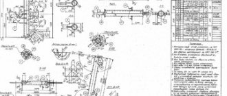
The example is quite conventional: in real conditions, they try to compensate for bending loads on beams with other structural elements, which is what we see in the photo.
- M/W=R, where R is the strength of the steel grade, and W is the section modulus.
Obviously, the parameters R and W are constants that will have to be looked for somewhere. We will try to simplify the task for the reader:
| steel grade | Strength (R), kgf/cm2 |
| St3 | 2100 |
| St4 | 2100 |
| St5 | 2300 |
| 14G2 | 2900 |
| 15GS | 2900 |
| 10G2S | 2900 |
| 10G2SD | 2900 |
| 15HSND | 2900 |
| 10HSND | 3400 |
The second parameter - moment of resistance - can be found in the same assortment tables in GOST 8645-68 and 8639-82. So, for a pipe with a cross-section of 180x150 with a wall thickness of 12 mm along axis A (along the wider side) it will be 346.0 cm3, and along axis B - 310.8 cm3.
Let's try to select the pipe size for our balcony with a load of 250 kg and a reach of 1 meter, based on the following conditions:
- The load falls on only one of the load-bearing corrugated pipes (three people are positioned so that their weight is not distributed over adjacent beams).
- The material used in the manufacture of the load-bearing frame of the balcony from pipes is St4 steel.
So, let's start the calculations.
- 25000 kgf*cm/W = 2100 kgf/cm2/W. The moment of resistance, therefore, should not be less than 25000 kgf*cm / 2100 kgf/cm2 = 11.9 cm3.
- Now all that remains is to select a pipe with the corresponding W value in the assortment table. With a square cross-section, this condition is satisfied, in particular, by dimensions 50x6 and 60x3.5.
Note: we have found the minimum dimensions at which the beam will withstand the corresponding load; at the same time, they neglected the safety margin (for example, in case one of the hypothetical visitors to the balcony jumps), the own weight of the balcony and wear of the frame due to corrosion. In practice, these factors are leveled out by at least a threefold reserve of the moment of resistance.
As you can see, neglecting the safety margin is dangerous.