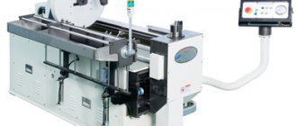
Not a single serious construction project today can be completed without the use of such an important element as reinforcement, which is largely responsible for the load-bearing characteristics of structures. That is why bending of reinforcement must be carried out professionally and in compliance with all generally accepted requirements.
Bending reinforcement 90 degrees using a special press. Home craftsmen don’t have such equipment, so we’ll make our own machine!
Useful tips
Do not try to bend the reinforcement with your bare hands by stepping on it.
Even thin pins will require at least a vice mounted on a workbench and a hammer. Refusal of devices and a reinforcement machine is fraught with a high risk of injury - there have been cases when such “dared souls” were seriously injured, after which they were taken away by ambulance. Do not bend the reinforcement with jerking movements. The process must be smooth: steel, no matter how ductile it is, experiences tension on the outside of the bend angle and compression on the inside. Jerks and bending of rods too quickly violate cold bending technology. The rod heats up, causing additional microcracks at the bend. The jerk can cause the material to weaken and even break.
The bend should be smooth, and not polygonal and “wrinkled”, like heating and water pipes that are heated at the bend using gas welding or a blowtorch. Do not try to heat the bendable rod in any way - in a barbecue, on a fire, on a gas burner, by leaning it against a hot heating element on an electric stove, etc. Even pouring boiling water on it is not allowed - the rod must be at the same temperature as the air around it.
If you are unable to bend the rod, cut and weld both parts at the ends, at a right angle or another. Simply tying such pieces in places of constant shock-tension load (foundation, interfloor ceilings, fence) is unacceptable - the structure will delaminate in a few years, and the structure will be considered unsafe and dangerous for people to live (or work) in it. Do not use a rebar bender that is not designed to handle the required bar thickness. At best, the machine will bend; at worst, the supporting-moving part will break, and you will get injured or fall due to excessive force applied to the machine.
If the machine for fittings is assembled using bolted joints, make sure that the bolts, nuts, and washers are made of high-quality steel, as are the angles, rods, and profiles themselves. Often construction stores and hypermarkets sell fasteners made from cheap alloys in which the steel is diluted with aluminum and other additives that worsen its properties. You often come across low-quality bolts, nuts, washers, and studs. Check them carefully. It’s better to overpay a little, but buy good bolts made of alloy steel or stainless steel, than to use those made of “plasticine” steel, which easily deforms with any noticeable force.
Avoid fasteners made from consumer goods - these are suitable, for example, for fixing roofing iron and plastic sheets, once screwed to beams and resting on them. But such bolts are not suitable where constant impact load is required.
Do not use a thin-walled profile used for installation of plasterboard floors and siding panels to make a bender. They can’t even bend a 3-mm rod - the corner itself is deformed, and not the bending reinforcement. Even several of these corners, nested one inside the other, will make the structure very problematic; bending with such a dubious device is unacceptable. Use a profile of normal thickness - made of the same steel as the rods themselves. Ideally, there is a piece of rail for the device frame. But this is very rare.
A well-made reinforcement bender will quickly pay for itself. Its primary purpose is to make a frame for the foundation of a private house and extensions, and a fence as a fence. And if you are also an experienced welder, you will begin to bend fittings to order, as well as weld doors, grilles, and fence sections from it, then such a device will allow you to earn extra money.
To learn how to make a reinforcement bender with your own hands, see below.
The correct reinforcement bender for yew trees
If you do not need a simple manual machine for bending reinforcement, but a universal device for performing various tasks, then pay attention to this design.
The idea and production of a homemade device belongs to the author of the YouTube channel “IGOR ANDREYCHUK”.
The practicality and functionality of a homemade device can be explained very simply - by using different equipment, you can perform different operations with metal.
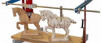
The machine can not only bend reinforcement at right angles, but also make decorative curls and twist round steel bars.
The capabilities of this device can be seen in the photo below.
Bar winding
Making a curl
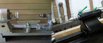
Let's now look at the main stages of manufacturing and assembling a homemade bending device.
Step one - we make the housing bearing.
To do this we need a bearing of a suitable size and a piece of pipe. We select a pipe of such diameter that the bearing fits freely into it, but the gap should be small.
Cut a piece of the required width from the round pipe. Using a grinder with a cutting disc, we make a cut in the wall of the ring.
We insert the bearing inside the ring and tighten the edges with a clamp. Then we scald it.
Step two - we make a seat in the bearing for installing the equipment.
From a metal corner 30x30 mm we cut two identical pieces. We apply them to a 30x30 mm profile pipe and scald them. We grind the corners with a grinder.
We insert the corrugated pipe with the corners inside the bearing, and weld the corners to the inner race. Then we remove the profile pipe and scald the upper part.
Step three - we make a handle with seats for the stop.
To make the handle of a bending machine, you can use a rectangular profile pipe. Cut a piece of the required length. The seats for the emphasis can be made from a round pipe.
We select a pipe of a suitable diameter, and then cut off six small pieces (barrels or bushings) from it. Then we weld them together.
The professional pipe handle must be attached by welding to the outer race of the bearing.
A previously made block of six bushings is welded to the side of the handle. Then the standard procedure is performed - cleaning the welds and the metal itself, and painting.
Step four - making a stop for the workpieces.
It's very easy to make. You will need a bolt, bearings and a nut. We insert the bolt into one of the seats on the handle, put bearings on it, and secure it with a nut.
Step five - preparing
a homemade bending device for work.
We install the equipment required for the job into the bearing (they are manufactured separately for specific needs). We clamp the lower part of the equipment in a bench vice.
Then, at the required distance from the equipment, we install a stop for the workpieces.
To bend the reinforcement you will need a lever handle. It can be made from rods of corrugated fittings, to the ends of which sections of corrugated pipe must be welded. We hammer the handle into the profile, welded to the outer race of the bearing.
You can also clamp the device itself in a yew. In this case, the lever handle will be inserted into a special attachment, which is installed on top of the equipment.
How to make a reinforcement bender with your own hands is shown in all details in the video below.
Reinforcement bender
Overall, the design turned out to be practical and functional. And the costs of time and materials for its production are quite adequate.
Do-it-yourself manual reinforcement bender. Drawing, description
In order to make a simple reinforcement bender you will need:
- steel base, which can be used as a part of a steel sheet with a thickness of at least 6 mm;
- steel angle with dimensions from 40×40×2 and a length of at least 4...5 times the length of the largest horizontal dimension of the reinforcing bar - rotary lever (the longer the lever, the lower the bending force);
- a rolling bearing unit in which the drive arm will rotate;
- reinstallable stops - steel angles fixed in the drive lever;
- guides - bushings made of tool steel type U8, freely rotating on their axis. To properly guide the workpiece along the base, there should be two of them, but for the simplest work one is enough. It is better to harden the bushing to HRC 50…55;
- wooden handle mounted on a lever.
Installation of such a bender is simple and does not require the use of welding equipment. The base is securely fixed to the workbench, after which the desired size of the corner is selected - a blank for the swing arm. Grooves are milled or drilled into it for installing stops, the locations of which correspond to the dimensions of the required reinforcement (however, a through groove can also be provided). The bearing and guide bushings are attached to the desired location on the base.
Using such a device, you can perform horizontal and vertical bends at arbitrary angles. To increase accuracy, you can provide a manual reinforcement bender with a dimensional scale.
Requirements for bending reinforcing bars
For bending reinforcement of large cross-sections, powerful factory-made machines are used; for rods of small cross-sections, you can use hand-made devices made by yourself. Such homemade devices are quite suitable for bending mounting loops, hooks, and tabs. Homemade devices are used for bending rods with diameters of no more than 14 mm when it is necessary to bend small batches of reinforcement. Most often popular among private developers.
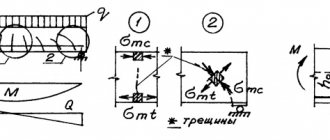
To maintain the performance characteristics of the rods when bending, the following conditions are observed:
- The bend angle should not be less than 90°.
- The radius of rounding at the bend is at least 10-15 diameters.
- The equipment used must correspond to the diameter of the bars being processed and the strength class of the reinforcing steel, otherwise folds may form on the inside of the resulting angle, and cracks on the outside. Also important points are: correct adjustment of the device and reliable fixation of the rod.
It is not recommended to practice traditional methods using high-temperature effects, including the following steps:
- using a grinder to cut the bend of the reinforcing bar;
- heating the bend with a blowtorch or other open flame source;
- bending to the required angle.
When using this method, mechanical characteristics are reduced at the bend due to cuts and exposure to high temperatures. When exposed to loads on such a rod, it may collapse. If the project does not have permission to use this bending method, it is not recommended to use it.
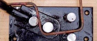
Electrical diagram of the machine for bending reinforcement SGA-1
List of electrical equipment of the machine for bending fittings SGA-1:
- Electric motor - M
- Magnetic starter - KM-1.KM-2
- Circuit breaker - SA1
- Pedal limit switch - SQ1
- Reverse limit switch - SQ2
- Limit stop switch - SQ3
- Thermal relay - RT1
- Stop button - K1
When the circuit breaker (SA1) is turned on, power is connected to the machine.
When the pedal is pressed, the contacts of the limit switch (SQ1) close and the bending disk rotates clockwise. When switching the contacts of the limit switch (SQ2), the bending disk returns to its original position until the contacts of the limit switch (SQ3) open, and the motor stops. The repeated cycle of machine operation occurs in a similar way.
Homemade machine design
The manual machine has a fairly simple design, and to make it yourself, it is enough to refer to a competent drawing of the device. The basis is a metal frame, to which a round pin or an ordinary corner is welded. Another element is the rotating platform, to which the lever, bending and central pins are welded. The distance between the pins is dictated by the maximum diameter of the reinforcement being processed. In order to be able to bend rods Ø6−12 mm on such a manual machine, the legs of the frame are securely fixed to the floor.
All elements of a portable homemade machine are fixed on a massive plate. This, also portable, plate can be secured at the work site with bolted joints or with the help of special pins welded to its lower part. A homemade machine can only be used for bending metal rods whose diameter is no more than 10 mm.
Preparation of materials and tools
Before making a bending machine, read the available drawings or make your own. The thickness of the reinforcing rod and their number are important as initial data. The safety factor of the device, which exceeds the effort required to bend the existing reinforcing bars, is chosen to be at least three times larger if the business is put into production and you are bending reinforcement for a large number of customers, or a grandiose construction project is planned.
If the drawing is selected, the following tools and accessories will be required.
- Grinder with a set of cutting and grinding discs. Without it, sawing a massive profile and reinforcing bars is difficult.
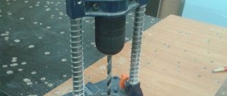
- Electric drill and suitable high-speed steel drill bits.
- Welding installation and electrodes.
- A hammer, a sledgehammer, powerful pliers, a chisel (file), a center punch and several other tools that no mechanic can do without.
- Vise for workbench. Since the structure is powerful, it must be fixed.
The materials you will need are:
- corner profile (25*25 mm) 60 cm long;
- steel rod (diameter 12-25 mm);
- bolts 2*5 cm, nuts for them (20 mm in inner diameter), washers for them (can be screwed).
The device you will make weighs more than one kilogram. The reinforced weight and massiveness of the entire structure will provide the strength required for bending the reinforcement.
A device (manual machine) for bending reinforcement with your own hands
The principle of operation of all designs of manual devices for bending metal (sometimes called manual machines) is the same: a “lever of the first kind” is used. If you have:
- the desire (initiated by need) to create a bending device for reinforcement;
- plumbing skills;
- necessary tools (including a bench with a vice)
- then you have come to the right place. With our hint, you can create a device (manual machine) for bending reinforcement with your own hands. The device of the proposed design can bend steel reinforcement with a diameter of ≤ Ø 15 mm.
What tool will you need?
In addition to a set of plumbing tools, which every skilled owner has for performing “work around the house and in the country,” you will need:
- any welding machine. You will perform MMA welding on it;
- electric drill;
- cutting machine (angle grinder) and cutting disc “for steel”;
- abrasive machine.
Description of the bending device
The bending device consists of two parts:
- motionless. It's called the base;
- mobile. It's called a lever.
The processed rod is placed between the mandrels and is deformed under the influence of a pin installed on the lever. The amount of force is determined by the length of the lever handle (usually about 500 mm long) and the physical capabilities of the mechanic. If necessary, provision should be made for extending the handle (for example, with a hollow pipe).
Manufacturing technology of fixtures for bending reinforcement
It is necessary to prepare 3 mandrels Ø 20 mm and a pin Ø 25 mm, 50 mm long each (see drawings). The lever should fit freely onto the pin. This is achieved by processing a size of Ø 25 mm on the pin using an abrasive machine.
Base
For the base, we cut out a steel plate with a thickness of ≥ 10 mm (see plate drawing below). Drill holes on it:
- Ø 20 mm for mandrel;
- Ø 25 mm for pin.
The basis of the bending device.
If you are the happy owner of a durable and strong workbench, you can drill 4 holes Ø 8...10 mm (indicated Ø 8 mm in the drawing) in the base to attach the fixture to it. If the strength of the workbench is in doubt, then the base should be welded to a corner 100 x 100 (mm) with a length of 1000 mm and the above holes should be drilled in the corner for fastening. Insert a mandrel and a pin into the drilled holes Ø 20 mm and Ø 25 mm (as shown in the drawing) and weld.
Lever arm
For the lever, we cut out a steel plate with a thickness of ≥ 10 mm (see plate drawing below). Drill holes on it:
- Ø 20 mm for mandrel;
- Ø 25 mm for pin.
Bending device lever.
We weld a mandrel and a handle Ø 20 mm and length 550 mm to the lever. To prevent industrial injuries, you can put some kind of protection on the end of the handle (for example, a plastic champagne cork).
Conclusion
After all work has been completed, the welding area should be cleaned from welding slag with a carriage brush. All sharp edges should be “filled” using a fine file. The device will be used outdoors, and therefore an anti-corrosion coating should be provided - in this case, pentaphthalic paint of the "PF" type is sufficient (just do not forget to prepare the surface - clean it with an appropriate solvent). At the junction of the lever with the pin, the surfaces should be lubricated with any grease (solidol, autol, grease, etc.). The condition of this unit should be constantly monitored and lubricated (this will greatly facilitate your work and extend the “life” of the device).
Operating rules
The principle of operation of this device is extremely simple - it is easy to understand if you look at the photograph. Simple safety rules should be followed:
Video
The video shows how it works, the machine is a little different, but the essence is clear.
Compliance with these simple requirements will save your health.
;
Address: 117997, Moscow, st. Obrucheva, house No. 21;
Phones: +7-(495)-647-92-71, +7-(495)- 647-69-81;
The company sells a manual machine for bending reinforcement with a diameter of up to 16 mm. Cost: 3999.00 rubles.
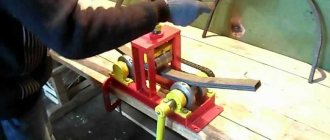
Bending machine from scrap metal scraps
You can make a simple reinforcement bender with your own hands even from unnecessary scraps of metal that are lying around in scrap metal.
A version of this bender design was shared by the author of the YouTube channel Fawa Bros. We will take this as a basis.
The first step will be to manufacture the moving part of the structure.
We cut out a blank of the required shape from sheet metal. Then you need to drill a hole and attach by welding a section of a pin onto which a thrust roller made of a round pipe is placed. Screw the nut onto the stud.
We weld the bearing to the bottom of the workpiece.
A metal plate of rectangular or square shape is suitable for the base - whichever you prefer.
We drill mounting holes in it in the corners, and another one closer to the central part.
We install a previously made part with a bearing on the plate, and fix it with a steel round timber, in the upper part of which there is a groove so that workpieces can be inserted.
The lower part of the round steel will need to be welded to the base of the reinforcement bender.
Next, we weld a piece of profile pipe to the moving part, onto which the lever handle will be placed.
We weld a piece of a square rod to the metal plate, on top of which we need to weld an elongated coupling. We screw a bolt into it, which in this case serves as a travel limiter for the moving part.
At the last stage, all that remains is to make the handle and install it.
The handle additionally has a movable stop, with which you can adjust the bending length of the workpiece.
How to make a compact device for bending reinforcement with your own hands is shown in all details in the author's video.
DIY Tool | Make A The Simplest Metal Bender | Homemade Metal Bending Tool
As in previous cases, the homemade product turned out to be simple and easy to use. The square plate is attached to the table using bolts, and you can immediately start working.
Reinforcement bending machines
According to the type of force with which the bending force is created, machines are classified into:
- manual,
- hydraulic,
- pneumatic,
- electromechanical,
- electromagnetic.
Using hand-held machines, it is possible to produce products from reinforcement with a diameter of up to 14 mm. If you need to manually bend reinforcement with a diameter of more than 14 mm. Then you should use the correct plate and a set of special keys. Manual production of curved reinforcing bars is advisable only for small volumes of work. Increasing the productivity of such manual labor is achieved by using machines for simultaneous processing of several reinforcing bars.
Other types of machines are distinguished by high productivity, precision of the manufactured configuration and the ability to bend reinforcement of any diameter. At the same time, they usually have various functions that increase productivity, small dimensions and the ability to operate in an automated mode.
Bending reinforcement using special equipment allows you to avoid twisting of the product around the central axis. In addition, products bent in this way are characterized by high accuracy of geometric shape. This achieves a reduction in time and labor costs for performing operations to install reinforcement parts in the required design position, which creates a positive economic effect on any construction site.
More information
When creating the structural frame of concrete work, bending and cutting of reinforcement (steel rods to strengthen the concrete) is very often necessary. It is an easy-to-work material that is often used in landscaping, art, and other projects that require metal that bends easily. Conventional reinforcement is distinguished by its nominal diameter, which varies in increments of 1/8 inch (that is, “number 4” reinforcement has a nominal diameter of 1/2 inch (15 mm)). Reinforcement up to number 4, as a rule, can be bent and cut by hand. Larger diameter rebar is not usually used except for technical or industrial concrete work and usually requires special equipment such as hydraulic shears and bending machines.
For this article, we will assume that 1/2 inch rebar (number 4) is used, which is common and used in landscaping and residential concrete work.
- Tight bends almost always require the use of a vise, jig, or special tool.
- The reinforcement can be heated with a torch for precise control of the bending process. However, this is unlikely to be needed when working with reinforcement having a nominal diameter of 1/2 inch (15 mm).
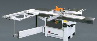
General view of the machine for bending reinforcement SGA-1EB (with Electronic Unit)
The SGA-1EB machine differs from the basic SGA-1 machine by the presence of an electronic unit that allows you to automate the bending process in conditions of mass production of parts from reinforcement.
The SGA-1EB machine has two operating modes - manual and automatic. The manual mode is convenient for single or small numbers of bends and is used when setting up the machine and checking sensors. You can work in manual mode if the sensors fail, which eliminates machine downtime. The automatic mode is used for repeated implementation of one or several successive bends.
Manual operation:
- When you press the pedal, forward rotation starts; when you release the pedal, the rotary disk stops (with virtually no overrun)
- When pressed again, reverse rotation is activated; when the pedal is released, the rotary disk stops
The automatic operating mode has two submodes:
- Single bend mode
- N-bend mode on one of eight programs
A shockproof display is installed on the side panel, which indicates the “Set Value” of the bending angle. To change the “Set Value” of the bend angle, use the +/- buttons. When you press the button briefly, the “Set Value” changes by 1 degree, and when you press it for a long time, it changes by 10 degrees.
Machine for bending reinforcement - classification and design
A machine for bending reinforcement is equipment that allows you to give the required configuration to reinforced metal products.
Homemade machine for bending reinforcement
Devices are divided into types depending on the following criteria:
- design features;
- drive type;
- diameter of the bending rod.
The machine for bending reinforcement is of the following types:
- mechanical device with manual application of force;
- mechanized equipment powered by an electrical network.
Manually operated equipment has a number of advantages:
- simple principle of operation, reminiscent of the functioning of a pipe bender;
- reduced weight of the bending mechanism, ranging from 12 to 20 kg;
- mobility, allowing, if necessary, to quickly move equipment;
- low cost, allowing you to make a machine for bending reinforcement with your own hands.
Manual reinforcement bending machine Stalex DR-16
Mechanized equipment with an electric drive is used in industrial enterprises for the serial production of bent elements. The industrial reinforcement bender is distinguished by the following points:
- increased productivity, allowing you to bend 5-6 reinforcing elements in one minute;
- the ability to bend industrial reinforcing metal with an increased diameter;
- increased power of the electric drive station to 5 kW, allowing for significant efforts;
- the ability to work in automatic mode with remote control, as well as manual control;
- a stationary structure that provides for operation of the equipment at the installation site without moving;
- weight increased to 0.5 tons, making transportation difficult without the use of lifting devices;
- a sufficiently high cost that allows you to purchase the device only for industrial use.
In industrial enterprises, the cutting process is often combined with the deformation of rolled reinforcement. For this purpose special equipment is used. The design of such units uses:
- powerful hydraulic drive;
- electromechanical systems;
- electromagnetic mechanisms.
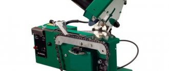
Machine for bending reinforcement with end cap TCC GW 40A
Depending on the diameter of the metal that needs to be deformed, bending devices are divided into the following groups:
- lightweight, bending rods with a diameter of up to 2 cm;
- medium, bending metal rods with a cross-section of up to 4 cm;
- heavy, designed for bending workpieces with a diameter of up to 9 cm.
Improved bending quality is provided by hydraulic devices. When the metal is deformed, there is no cracking or formation of folds, which are a source of internal stress.
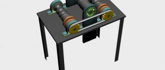
Kinematic diagram of the machine for bending reinforcement SGA-1
- Electric motor
- Pulley d1 = 98 mm
- V-belt
- Pulley d2 = 260 mm
- Ball bearing No. 208
- Gear z = 19
- Gear z = 37
- Gear z = 16
- Gear z = 40
- Worm z = 2
- Worm wheel z = 60
- Roller bearing No. 7310
- Ball bearing No. 118
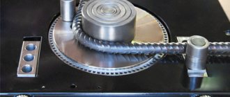
The machine for bending reinforcement SGA-1 consists of a frame, gearbox, plate, devices for bending rods, electrical equipment and pedal control. On the upper part of the welded frame there is a plate with a gearbox and a device for bending rods, and in the lower part there is a sub-motor plate for mounting the engine and moving it when the belts are tensioned. The plate serves as a gearbox cover and a machine work table. Bars with holes for thrust pins and bending devices are welded to the plate, and rollers are attached to support reinforcing bars on them. To remove scale, the plate is equipped with a funnel with a flange fastening for connection to the workshop exhaust ventilation.
A device for bending rods consists of a bending disk, a bending pin attached to it, a central pin with a roller, and a thrust pin (pin) with a roller. The bending disk has holes with bushings for installing the bending pin, as well as holes located around the circumference for installing stop and reverse cams that act on the corresponding limit switches. The bending disk is driven by a motor through a V-belt drive, two open gears and a worm gearbox. The rotation speed of the bending disk can be changed by rearranging the gears.
How to bend reinforcement without a special device
Here it is worth knowing that when trying to bend, especially alloyed reinforcement, with your own hands you need to consciously calculate your actions, otherwise this can lead to serious injuries. Alloyed rolled metal, if you try to deform it, will try in every possible way to spring back and can cause irreparable harm to your health. So be careful and attentive.
Let us highlight the three simplest ways to bend reinforcement with a diameter of up to 8 mm yourself without the use of special devices, namely:
Using two pieces of metal pipe. So, we will need tubes with a diameter of 15 mm with a length of 0.5 and 1 meter, which we put on the fittings. We stand on a half-meter piece of pipe with our feet, and, accordingly, we begin to lift the meter piece to the bend angle we need.
- If a five-centimeter piece of pipe 25-32 mm in diameter is electric welded to a one and a half meter metal pipe of 32 mm in diameter or a 50 mm steel angle, you will get a universal bending lever. All that remains is to either stand on the reinforcement or rest it against something strong.
- Not very long pieces of reinforcement can be bent using a large vice and a sledgehammer. Only with this method you shouldn’t rush and you need to hit with a little force, stretching the process, otherwise you can simply break the reinforcing bar.
The main disadvantage of using such methods for bending reinforcement is that the turning radius is quite large and often the angle turns out to be somewhat curved and does not lie with its sides strictly in the same plane.
How to make a device for bending reinforcement
Variant of reinforcement bender made from improvised means
Before starting production, it is necessary to make detailed drawings of the components of the future device. To do this, it is recommended to familiarize yourself with ready-made samples on the Internet, made according to a standard scheme, or choose some other technique than bending reinforcement.
A simple do-it-yourself reinforcement bender is easiest to do, based on the general principle of operation of this kind of device, namely, consisting of three main parts:
- massive base,
- rotating mechanism in the form of a large lever,
- strong support.
To make such a device, improvised materials and tools available in any normal garage are quite suitable. So, let's prepare the necessary tools for this, here we will need:
- angle grinder with cutting wheels and grinding disc,
- electric drill with a set of metal drills,
- electric welding machine with electrodes,
- standard set of hand tools.
Although an important step is the preparation of components and assemblies, here we will try to adapt various available materials. As a last resort, what is missing can be borrowed either from a neighbor or purchased in addition on the construction market.
Sequencing
- Let's make the base. To do this, we take sheet metal 3-5 mm thick, measuring 100 by 200 mm, or you can take a piece of channel size 10-15, 200-300 mm long. We drill holes in the corners of the base to allow fastening to a workbench or other massive object. An axial stop is firmly welded in the center of the structure using electric welding. This is a steel shaft with a height of 50 mm and a diameter of 14 mm. For this part, you can take any M14 bolt of suitable size, the head of which must be sanded off, leaving a thickness of 3 mm - this will make it possible to create a strong welded connection with the base.
- We make a rotating mechanism. A steel strip 5 mm thick, 50 mm wide and at least one meter long is suitable for this. In the absence of a strip of the required length, you can take a shorter one, but weld the length of the lever using a steel pipe 32-50 mm in diameter. To one edge of the strip we electric weld a piece of metal pipe 50 mm long and 15 mm in diameter, which will fit like a roller on the axial stop. We retreat 50 mm from the roller along the longitudinal axis and weld a rotary stop, for which an M10 steel bolt, also with a pre-ground head, is suitable. You can also make and put a ring on the rotary stop, which will serve as a roller, which will improve the operation of the device. As an option, you can make a lever from a 50 mm steel angle; to do this, you need to cut off 50 mm of the shelf vertically at the point of attachment to the axial stop; the remaining part of the shelf will serve as a rotary stop.
- We electric weld a fixed stop to the base, for which a 50 mm piece of angle 50-100 mm long is suitable. The place of its attachment should be 100-200 mm from the axial stop with a displacement from the central axis of the base of no more than 20 mm, which is determined by the thickness of the reinforcement.
- We assemble the finished structure. We firmly attach the bases of our finished device to a mechanic’s workbench or other similar massive object in the surrounding environment. We put the rotating mechanism roller with a lever on the axial stop.
- We run in the finished machine for bending reinforcement and check its operation at idle, using soft metal for this. If everything works, then we begin to manufacture the parts we need from the reinforcement.
If the machine for bending reinforcement has its own stationary frame, then it is worth advising to make a couple of additional improvements to it, namely:
- apply linear markings on both sides of the axial stop, which will allow you to measure the length of the bent part of the bar without using a tape measure;
- Apply radial markings of the main angles of 30, 45 and 60 degrees around the axial stop, which will also make working on such a machine much more convenient.
Information about the manufacturer of the machine for bending reinforcing steels model SGA-1
The manufacturer of the machine for bending reinforcing steel model SGA-1 is the Construction Machines in St. Petersburg.
On the Russian construction equipment market there are several domestic developers and manufacturers of machines for bending reinforcement, and many foreign companies from China, Turkey, Bulgaria, Italy, etc.
The most famous Russian manufacturers of machines for bending reinforcing steel:
- Astrakhan Machine Tool Plant - electromechanical bending machines SGA-40, SGA-55, SGA-55U
- Dolina – Kuvandyk plant KPO – electromechanical bending machines MGA, MGA2
- PromStroyMash , Barnaul - electromechanical bending machines UGA-40
- Construction machines St. Petersburg - electromechanical bending machines SGA-1 , SGA-1EB, SGA-50, SMZh-179
- Unitech Novocheboksarsk - electromechanical straightening and bending machines SMZH-173.03