Almost all modern electronics, including tablets, laptops, smartphones, etc., contain surface-mount chips on their motherboards. The design of such microcircuits differs in that instead of the classic wire leads, it contains a ball array. That is, a certain number of metal contact points, which in fact represent pieces of solder in the form of small balls. Such balls, accordingly, cannot be inserted into traditional holes on the board, but BGA chips can be soldered to mounting pads. This is surface mounting. Let's look at how to solder BGA chips, as well as the necessary equipment for the job.
Soldering bga chips
How to solder boards? And how does BGA stand for? Bgacenter experts answer these two frequently asked questions during soldering courses. From English - ball grid arrey, that is, an array of balls that looks like a grid. Solder balls are applied to the microcircuit through a stencil, then a stream of hot air melts the solder itself and contacts of the correct shape are formed.
And the soldering process consists of a certain sequence of actions, following which we obtain a high-quality connection. But there are a large number of nuances for which people come to study.
Starting with at what angle and at what distance from the board to hold the hair dryer nozzle, temperature conditions for dismantling and installing microcircuits, from which side to start the paddle. And during diagnostics, and there is an interlayer short circuit, nothing heats up.
How to find the faulty element or circuit in this case? And many other subtleties that a current service center master can know. And the one who can confirm his level with completed repairs.
iPhone repair at Bgacenter
Reballing procedure
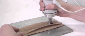
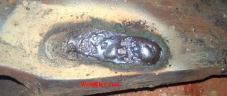
To carry out reballing, the chip is placed in a stencil and secured with specialized electrical tape. Apply solder paste on the back side with a finger or spatula, then set the hair dryer to a temperature of about 300 degrees and begin to warm it up. After the characteristic shine from the molten solder paste appears, allow the solder to cool completely.
To free the stencil from the chip, remove the electrical tape and heat the stencil to approximately 150 degrees; at the end of the procedure, the part should be free. It happens that it is impossible to immediately remove a part from a Chinese stencil, so it may be necessary to carefully hook it.
During reverse soldering of the microcircuits, the risks are assessed and the chip is laid out the required number of times to ensure an exact match of the heels and balls. Then they set the temperature on a soldering hair dryer to 330 to 350 degrees and heat until the melted solder allows the chip to fall into place on its own.
Source
Soldering the chip
90% of the success of the repair depends on the correct dismantling of the microcircuits. It is at this stage that it is important not to tear off the nickels and not damage the microcircuit with high temperature. And they begin desoldering the chip by removing the compound.
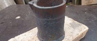
Compound
Compound is a polymer resin, usually black or brown, used in the manufacture of telephone motherboards. Purpose of the compound:
- Additional fixation of radio components and bga chips on the board.
- Protection of non-insulated contacts from moisture.
- Increased board strength.
The most critical microcircuits, such as: CPU, BB_RF, EPROM, NAND Flash, Wi-Fi, are filled with compound at the factory after installation. And before dismantling, it is necessary to clear the perimeter of resin.
Removing the compound
Dismantling sequence
- Carefully inspect the board for previously performed repairs.
- Perform diagnostics and take the necessary measurements.
- Prepare the board for soldering, remove protective screens and stickers. Disconnect and remove the coaxial cable.
- Secure the motherboard in the appropriate holder.
- Remove the compound around the chip being removed. The temperature on the hairdryer is 210 – 240 degrees Celsius.
- Install heat sinks. The installation location of the heat sinks depends on the location of the soldered chip.
- Use a hairdryer to warm up the board for a few seconds. Thus, we increase the temperature of the board so that the flux spreads evenly.
- Apply FluxPlus, or any other no-clean flux, to the surface of the chip.
- Direct a stream of hot air onto the element to be soldered. Temperature during dismantling is 340 degrees Celsius. How can you tell when the solder has melted and it’s time to remove the chip from the board? There are several ways to do this:
- Track time using a stopwatch.
- Count down the seconds to yourself.
- “Push” with a probe or tweezers the microcircuit itself or the nearby harness (capacitors, resistors or coils). As soon as the chip being soldered begins to move, by a fraction of a millimeter, it is time to place the spatula under or use tweezers.
- Prepare the contact area. For this:
- Use a special spatula to remove any remaining compound;
- tin all contacts without exception with Rose alloy;
- use braid to collect solder residues from the working surface;
- After the motherboard has cooled to room temperature, wash the contact pad with alcohol, BR-2 or DEAGREASER.
- The board is prepared for installation of a working microcircuit.
Soldering chips
How to desolder a radio element
Soldering DIP chips
- Sequence of actions for desoldering:
- Remove varnish from the chip solder areas with a brush or cotton swab dipped in acetone or remover (in the case of a varnished board).
- Remove any remaining solvent and varnish with a brush dipped in ethyl alcohol.
- Heat the soldering iron to operating temperature.
- Touch the soldering iron tip to the first leg of the chip (on the back of the board) until the solder completely melts.
- Remove melted solder with a suction syringe. When using a needle instead of a syringe, place the needle on the leg of the chip and, turning the needle around its axis, lower it all the way into the hole.
- After completely removing the solder from the hole, start desoldering the leads from the next hole.
- Remove the microcircuit after all pins have been completely unsoldered.
On video: How to properly desolder a DIP chip
Dismantling planar chips
The sequence of actions for desoldering SOIC - chips that are not glued to the board:
- Remove varnish (if any) from the legs of the microcircuit with acetone or remover. After removing the varnish, clean the board from any remaining varnish with ethyl alcohol.
- Apply liquid flux to the soldered leads on all sides of the chip.
- Solder (short circuit) all the legs of the chip on each side, passing the tip along all the pins of the chip and dispersing the solder along the legs. There should be a lot of solder applied to the legs so that after removing the soldering iron, the solder continues to be in a molten state.
- Run the soldering iron over all sealed sides of the chip, ensuring the solder melts on all sides, then remove the chip with tweezers.
- To unsolder a microcircuit glued to the board, you need to unsolder each pin of the microcircuit one by one, lifting it with tweezers above the contact pad. After unsoldering all the legs, remove the microcircuit mechanically (with a knife), being careful not to damage the board.
On video: How to dismantle a planar microcircuit
Soldering microcircuits with pins
Soldering should be done in the following order: 1. Install the chip into the holes on the board. 2. Apply flux to the pins of the microcircuit on the back side of the board. 3. Solder each pin of the chip into a hole on the back of the board. 4. Remove any remaining flux.
Installation of SOIC chips
It is convenient to solder SOIC chips using a “wave of solder”. The method is based on the capillary effect, under the influence of which liquid solder flows between the lead and the metallized area, wetting them and forming a drop.
Soldering microcircuits with a “wave solder” using a soldering iron is carried out in the following sequence:
1. Tin the contact pads and apply flux to them. 2. Install the chip on the board, align the legs with the board pads and solder one corner pin (any). 3. Solder the second corner pin to the metallized pad, located diagonally on the chip opposite the first soldered leg. At the same time, make sure that the remaining pins of the microcircuit are aligned with their metallized pads. 4. Apply flux to all pins of the chip. 5. Pass the tip over the pins on each side of the chip several times to disperse the solder across the pins. 6. If solder bridges have formed between adjacent terminals, remove the excess using metal braid. It should be placed on top of the jumper and heated with a soldering iron tip. Excess solder will be absorbed into the braid. Then run the soldering iron tip across the leads again.
Soldering bga chips
The general principle of soldering is as follows: thanks to the surface tension created when the solder melts, the microcircuit is fixed relative to the contact pad on the system board. Soldering temperature for bga chips on iPhone boards is 320 – 350 degrees Celsius.
Preparing the chip:
- Use a special knife to clean the compound.
- Use a 1 or 2 mm copper braid (depending on the geometric dimensions of the chip) to remove any remaining solder.
- Restore the ball leads. There are two ways to draw conclusions:
- BGA paste is applied through a stencil to the surface of the microcircuit (priority method) Used in most cases.
- Manually, with BGA balls. This option is suitable for chips with a small number of pins, up to 50. Although a few years ago, when the quality of stencils left much to be desired), modems on the iPhone 5S were rolled manually. That is, each ball was installed separately using a probe or tweezers. And this is 383 contacts, as calculated by ZXW. If, when distributing balls on a chip glued to a stencil, the balls are not fixed in the holes of the stencil; this means that not enough flux has been applied to the microcircuit.
- If we are working with paste, be sure to warm up the microcircuit with a hairdryer after removing the stencil to form contacts of the correct shape. Additionally, fine-grained sandpaper, P500 GOST R 52381-2005, can be used for these purposes.
- Use alcohol and a toothbrush to finally clean the microcircuit.
- Solder the chip onto the contact pad, installing it along the key and gaps.
- When installing a new microcircuit (purchased from a supplier), a mandatory procedure is to roll the chip onto lead containing solder. This is necessary to lower the melting temperature of the solder and reduce the time the board is exposed to high temperatures.
Soldering bga/BGA soldering
Suitable brands
There are different types of solders for soldering, but it is worth highlighting the most suitable for working with microcircuits that can be found on the modern market. One of the most common options is POS 61. It has the following chemical composition:
| Chemical element | Composition ratio, % |
| Tin | 61 |
| Lead | 38,5 |
| Iron | 0,02 |
| Bismuth | 0,01 |
| Antimony | 0,05 |
| Nickel | 0,02 |
| Sulfur | 0,02 |
The technical characteristics of the material are as follows:
| Melting temperature, degrees Celsius | Density of deposited material, g/cm squared | Thermal conductivity | Tear resistance | Elongation, % | Impact toughness, kgf/cm squared |
| 189 | 8,5 | 0,12 | 4,3 | 46 | 3,9 |
An analogue from the same POS 30 series can also be used. It is inferior in quality, but has a sufficiently low melting point to provide comfortable working conditions. Its composition has virtually no impurities:
Bottom heating for bga soldering
To reduce the time the board is exposed to high temperatures, the boards are heated. We recommend the monoblock PCB heater STM 10-6. Stable maintenance of the set temperature over the entire area of the heating element contributes to uniform heating of the entire motherboard (depending on the heater model). And one more advantage over other thermal tables is a convenient universal fastening system.
Thermal table STM 10-6
Safe work with semiconductor radio components
Before you unsolder a part from the board with a soldering iron, you need to know the following. Semiconductor elements are extremely sensitive to overheating. Also, tracks on a printed circuit board at high temperatures or when the soldering time is exceeded can peel off from the substrate or break, which is even worse.
Temperature conditions
How to test a zener diode with a multimeter
The temperature of the soldering iron tip should be 200-250⁰С. At higher temperatures, peeling of the printed tracks and overheating of the microcircuit may occur. The same goals are set for the soldering time of one leg - no more than 3 seconds.
Note! Some sites advise for dismantling to focus not on the temperature, but on the power of the soldering iron. It is not right. Their temperatures are the same, it’s just that a less powerful one may not be able to cope with melting the solder at the pin due to intense heat removal, and a too powerful one can easily overheat the pins and the board. The best option is a 40 W soldering iron.
Many microcircuits are sensitive to static electricity. It is necessary to work with an electrostatic wrist strap on and a grounded tool.
Electrostatic bracelet
Flux for soldering bga
There are a huge number of flux manufacturers on the market. Bgacenter uses the widely used FluxPlus. You should pay attention to the date of manufacture and expiration date of the flux. Advantages of flux gel:
- no-wash (many professionals recommend washing anyway);
- convenient dispenser, hence high dosing accuracy during soldering work;
- does not emit unpleasant odors;
- ensures good spreading of solder over the base metal, thereby reducing the surface tension of the molten solder.
FluxPlus
At home
Soldering microcircuits at home may be required to repair complex household appliances and computer motherboards.
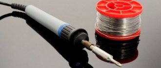
As a rule, to solder the legs of the microcircuit, use a soldering iron or soldering gun.
Working with a soldering iron is carried out using regular solder or solder paste.
Recently, lead-free solder with a higher melting point has become increasingly used for soldering. This is necessary to reduce the harmful effects of lead on the body.
What equipment will be required?
To solder microcircuits, in addition to the soldering equipment itself, you will need some other equipment.
If the microcircuit is new and made in a BGA package, then the solder is already applied to the legs in the form of small balls. Hence the name - Ball Grid Array, which means an array of balls. These enclosures are designed for surface mounting. This means that the part is installed on the board, and each leg is soldered to the contact pads with a quick, precise action.
If the microcircuit has already been used in another device and is used as used spare parts, it is necessary to perform a reballing. Reballing is the process of restoring the solder balls on the legs. Sometimes it is also used in the case of a blade - loss of contact of the legs with the contact patches.
To carry out reballing, you will need a stencil - a plate of refractory material with holes located in accordance with the location of the microcircuit pins. There are ready-made universal stencils for several of the most common types of microcircuits.
Solder paste and flux
For proper soldering of microcircuits, certain conditions must be met. If the work is carried out with a soldering iron, then its tip should be well tinned.
For this, flux is used - a substance that dissolves the oxide film and protects the tip from oxidation before being coated with solder during soldering of the microcircuit.
The most common flux is pine rosin in a solid, crystalline form. But to solder a microcircuit, such a flux is not suitable. Its legs and contact spots are treated with liquid flux. You can make it yourself by dissolving rosin in alcohol or acid, or you can buy it ready-made.
In this case, it is more convenient to use solder in the form of filler wire. Sometimes it may contain powdered rosin flux inside. You can purchase a ready-made soldering kit for soldering microcircuits, which includes rosin, liquid flux with a brush, and several types of solder.
When reballing, solder paste is used, which is a base of viscous material that contains tiny balls of solder and flux. This paste is applied in a thin layer to the legs of the microcircuit from the back of the stencil. After this, the paste is heated with a hairdryer or infrared soldering iron until the solder and rosin melt. After hardening, they form balls on the legs of the microcircuit.
Hot air soldering station
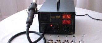
The purpose of the Quick 861DE ESD Lead station is soldering (disassembly and installation) of BGA microcircuits and SMD components. Advantages of this station:
- three memory modes CH1, CH2, CH3;
- high air-to-air performance, Quick 861DE is suitable for soldering circuit boards, phones and laptops;
- temperature stability.
What could be improved in the design of the station is temperature control not with buttons, but with rotary controls, as on the Quick 857D (W)+.
Quick 861DE ESD Lead
Board design
How to test a resistor with a multimeter
Printed circuit boards differ in the number of printed layers and the method of installing radio components:
- Single layer;
- Double layer;
- Multilayer;
- For DIP elements;
- For SMD components.
One board can contain both DIP and SMD elements on one or both sides. Multilayer printed circuit boards, in addition to outer layers, have internal ones, which usually serve for general shielding or wiring of power circuits. Thus, the motherboards of modern computers or mobile phones have up to seven layers.
Multilayer PCB
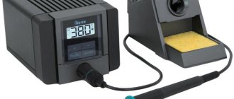
Soldering iron
PS-900 METCAL – induction soldering system. A soldering iron power of 60 W is quite enough to work with multilayer boards of modern electronics. Phone repair engineers have 4 years of experience working with this particular soldering iron. What are the distinctive features of the PS-900:
- no need for calibration,
- large selection of tips,
- reliability of the station, the consumable material is the inductor. With daily intensive soldering, the inductor is replaced on average once every 10 months.
Soldering iron
Heating from below
This technique is not only useful when working with a soldering gun, but also increases the convenience of soldering.
The board is secured with a clamp, the temperature is set to 200 degrees and warmed up for five minutes, after which they begin to work as usual.
Using thermal tape, you can shield nearby elements.
After removing the chip, the contacts are cleaned with the above braid. Do the same with the board.
All procedures must be carried out carefully to prevent damage to the circuit. If you don't have copper braid on hand, you can remove the solder using a soldering iron with a thin tip.
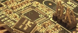
Binocular microscope
For a novice phone repairman, the CM0745 microscope is a good option. Binocular microscope with a focal length of 145 mm (with a Barlow diverging lens installed). The purpose of the lens system is to increase the focal length while maintaining the working area.
Advantage of CM0745:
- Smooth increase is achieved using a ratchet.
- The lens system is made of glass, not plastic.
- Possibility to equip the microscope head with different tables and stands.
- Magnification up to 45X.
Microscope for soldering circuit boards
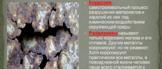
What is compound and how to remove it from the board
The compound is a resin that increases the strength of the board and reduces the operating temperature of the microcircuits. Also saves the board when exposed to moisture
If you need to resolder the chip, the compound will have to be removed. It is applied in different ways. Manufacturers can coat the edges of contacts with SMD parts. Or they can fill it completely.
How to remove resin from a board
Can be removed mechanically. To do this, heat the board with a hairdryer to 150 °C and use a toothpick or metal tweezers to remove pieces of the compound from the board. It's not always possible to do this.
You can also try chemical solvents. Typically sold at mobile phone parts stores.
And in order to desolder a microcircuit that has a compound under the contacts, you need cutting tweezers. The soldering procedure is similar to the usual one, but this time you need to cut off the compound.
Dismantling by suction
This method of soldering microcircuits and other small parts is based on the principle of liquid suction by creating a vacuum in the contact area.
Vacuum, in turn, can be created using the following tools:
- a special device that operates on the principle of a bicycle pump (it is called a destin pump);
- suction in the form of an enema, which can be combined with a soldering iron and used simultaneously with heating the contact pad.
Suction structures can have a variety of designs (in the form of a piston with a rod, for example), but their essence does not change. They have been and remain the most effective means of removing liquid solder.
Using a razor blade
The main problem with soldering microcircuits is that they have several legs, which is why when one of them heats up, the others have time to cool down. This inconvenience can be overcome by using a heat-conducting device that contacts several legs at once.
In this case, the thermal power of the tip is distributed evenly between them and ensures that the solder melts in several contact areas at once. A simple razor blade can be used as such a device; to heat it up, you will need a soldering iron of suitable power or a hot air gun.
When heating the steel blade, it is recommended to slightly rock the chip on the soldered side, after which you can forcefully pull it out of the board. In the same way, the second row of legs is freed from solder.
Necessary tool
Soldering iron
Old models
A properly selected soldering iron can ensure normal heating of the contact tracks of boards and semiconductor leads.
The old EPSI model of the “Moment” type with a power of 65 watts has a universal design. It is not difficult to make it with your own hands.
Previously, resistive type models with a heating element made of thin nichrome wire were widely used.
Modern soldering irons
For specific soldering conditions, you can now purchase various types of models equipped with all sorts of functions.
For example, a soldering iron with tin suction has been specially designed for soldering microcircuits, transistors and diodes.
It quickly heats up a layer of solidified solder and easily removes it in a liquid state from the contact pad.
Radio component holders
When heating the transistor leg for tinning and soldering, you should always remove the heat from the body and semiconductor layer with some metal object.
For this purpose, tweezers or alligator clips are usually used. However, it is most convenient to work with a medical instrument with thin legs, which surgeons use during operations.
Fixing electronic boards
Radio components and boards are usually small in size and require reliable fixation in space. Soldering them while hanging is dangerous: a small wrong movement can damage the entire structure.
When working with them, one hand is already occupied: it contains a soldering iron. And the second one needs to perform some additional actions. In this case, factory or homemade vices, holders, and clamps come to the rescue. They must be used.
Soldering needles
At the moment the solder melts, they are inserted inside the board sleeve to separate the leg of the radio component from the contact track.
A home craftsman can buy a ready-made kit in a store, for example, via the Internet in China or your city.
Medical syringe needles are well suited for the same purposes. Their tips need to be sharpened to a right angle.
Molten Tin Removal Tool
There are several ways to remove liquid solder from the melt site:
- shaking onto the floor, table or other surface;
- sweeping with a brush or brush;
- suction;
- absorption into a special braid.
The first two methods are extreme; they are used in extreme cases. For normal high-quality work, the last two methods are suitable.
Liquid tin suction method
The tool adapted for it is called a tin pump. The appearance and design of one of the many models is shown in the picture.
Before work, the spring is cocked. When the solder is melted to a liquid state, the tip of the device is applied to it and by pressing a button, the force of the released spring is forced to move the piston to provide a vacuum, which draws the liquid metal into a special cavity.
Dismantling braid
It is made by weaving soft copper wire. Working with it is quite simple: a piece of braid is placed on the molten solder, and it quickly absorbs liquid tin.
Dismantling braid is sold in construction stores. An alternative can be a shielding core from an old coaxial cable for televisions, produced back in Soviet times. It is impregnated with a flux of alcohol and rosin.