A welding inverter has become an indispensable attribute of a professional or amateur welder. With the help of welding equipment, soldering or cutting of the alloy is done, and the suitcase for the welding inverter is designed to store the main units and components designed to work with alloy surfaces. For those who are constantly engaged in welding, the priority quality of work will be the comfortable placement and placement of the main parts and components that are intended for welding work.
Application of inverter case
Box for welding kit from a canister
Hello, readers of this site. Today I will tell you how I made a convenient box for transporting a welding machine from a plastic canister.
Most of the time I live in a city apartment. I have a workshop in the basement under a nine-story building, where I do my hobby - homemade things. There I can do everything except welding work - firstly, there is a 10-amp circuit breaker installed in the electrical panel, which can be knocked out if the electrode gets stuck (And the electrician has the key to the panel). Secondly - fire safety! And thirdly (and most importantly), the ventilation there does not allow welding.
Therefore, in order to perform welding work, I go to the country house or to a private house. And since I’m always short on time, most often, after work, I pop into the basement, grab everything I need, and go.
I use this welding inverter “Gerard-MMA200”.
He has served me faithfully for many years. I kept it in its “original” box. But the problem with all factory packaging, as you know, is that once you take out its contents, it is almost impossible to put everything back in! )))). Fortunately, a “souvenir” welder’s shield was supplied with the device! Without it, the device fit easily. But only him!
And so, I arrived at the dacha. I lay out the tool in anticipation of interesting work. . And then it turns out that I forgot my mask.
Another time I took both a mask and welding. but I forgot the electrodes. Next time I took everything except the cutting wheels. ))))).
It was events like these that gave me the idea to make some kind of box that would hold the entire set - a welding machine, a mask, wires, electrodes, clamps, a hammer. In short, grab one box, throw it in the car - and don’t forget anything! )))))
And I began to think about what I could make one out of! My choice fell on this 30-liter canister, of which I have quite a lot:
Having estimated, I came to the conclusion that this is exactly the volume I need. (To be honest, it wasn’t this particular canister that went under the knife. I just forgot to take a picture of the one I cut.))))
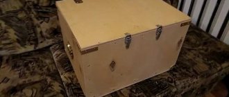
As a result, I ended up with a box, which you can see in this video (it was filmed crookedly, but sorry):
And now I will tell you in detail how I did it.
I needed:
1. Plastic canister 30 l. 2. Blind rivets with a diameter of 4.8 mm of different lengths. 3. Loops 2 pcs. 4. Chest latches 2 pcs. 5. Strips of tin. 6. Cuttings of PVC pipes. 7. Trim of linoleum. 6. M5 washers enlarged.
So, let's begin. At first I wanted to do a horizontal layout. But, after thinking about it, I came to the conclusion that, firstly, I would significantly lose the rigidity of the structure, and secondly, I was still going to carry it by the handle (i.e., vertically), and therefore it would be better if the tool was laid out will be done in the same position.
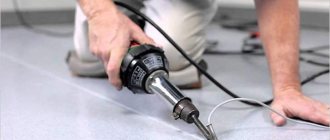
So I took the canister and cut off the top part:
These are just strips with a curved edge. Left over from something, I don’t remember. If necessary, they could be easily cut and folded.
I took a narrower strip and riveted it around the edge of the cut top part, using a regular rivet gun and pop rivets. At the same time, I slightly pushed the double-folded edge of the tin beyond the cut:
Receive a selection of new homemade products by email. No spam, only useful ideas!
*By filling out the form you agree to the processing of personal data
I make cable holders
The sequence of work is as follows:
- I cut pieces from a steel strip for holders, the size is selected arbitrarily.
- I drill a hole with a diameter of 8 mm in the middle; a steel rod with a diameter of 8 mm will subsequently be inserted and welded into it.
- I bend two corners from a rod with a diameter of 8 mm; they will be used as holders for the power cable.
- I cut off the curved elements; the length of both sides was 30 mm.
- I cut four pieces of 8 mm rod, 30 mm long. They are carefully inserted into pre-prepared plates and welded.
- I process the surface with a grinding wheel to level it to perfection. I round the corners and slightly bend the ends.
Case for welding inverter
A welding inverter has become a mandatory attribute of a professional or amateur welder. Welding equipment is used to solder or cut metal, and the case for the welding inverter is designed to store the main units and components designed to work with metal surfaces. For those who are constantly engaged in welding, the priority quality of the work will be the convenient location and placement of the main parts and components that are intended for welding work.
Application of inverter case
Features of industrial cases
The industry produces several options for boxes for welding inverters, but most equipment users believe that making a case with your own hands would be an excellent option. By the way, some developments of do-it-yourself welding inverter cases have become the basis for industrial production, which have gained popularity among welding specialists.
Industrial series have convenient compartments and sections for storing tools and other auxiliary components and parts. As a successful example of industrial production, we can point out the 18″ FIT case series, which has the following parameters:
- External overall size - 450*240*200 mm.
- The inner part of the case is 440 (390 mm internal working part) * 225 * 180 mm.
Appearance of FIT case 18″
The side handles used in this design allow the usable volume of only 390 mm. The height of this design is 180 mm, with a size of 145 mm allocated for the direct construction of the box, and 35 mm belongs exclusively to the closed part of the body in the form of a lid. The weight of this design is about 2.5 kg. As practical experience shows, this option is excellently used as a case for the welding inverter Resanta, Torus, etc. The only drawback is considered by many to be the inability to fully accommodate wires and cables provided for the design of inverter welding equipment.
Factory case of the Resanta welding machine
In any case, for some models it is still possible to “squeeze” cables, holders, and wires inside the box structure. The inside of the cover has a special recess that allows you to accommodate a pack of electrodes and the necessary minimum of protective equipment.
Unlike homemade options, which have to be made from handy materials, the welding inverter inside the case will not “dangle”, but tightly holds the main body of the inverter equipment. An additional advantage of serial production of the case for the Paton welding inverter will be a special varnish coating that will not change its appearance regardless of the condition of the main inverter welding equipment.
Preparing elements for the frame
Now you need to make blanks for the structure frame:
- To begin with, I bend two U-shaped blanks from a rod with a diameter of 10 mm. Their length depends on the model of your device, so it makes no sense to give exact dimensions.
- From the corner I cut two blanks for the lower part of the frame. The length is selected individually.
- I cut three elements from the strip according to the width of the future structure.
- In two previously cut strips, I drill holes in the middle with a diameter of 8 mm.
- I insert the previously bent elements into the holes and weld them, this will be a holder for the power cable.
Advantages of industrial designs
Considering that welding work is classified as complex and responsible, the presence of additional accessories and items intended for mobile carrying or long-term storage plays an important role in this. The advantages of industrial designs are as follows:
- The front part of the box body, bottom and back wall are made of a metal base.
- The side walls, as well as the closed part of the top in the form of a lid, are made of impact-resistant plastic with a suitable varnish coating.
- The service life is at least 5 years.
- The movable tray mechanism, as well as the built-in organizer components, are used to accommodate basic accessories and additional spare parts for inverter equipment.
- Universal and strong locks made of chromed metal add not only aesthetics, but also reliably protect the drawer from intentional opening.
An industrial case is more expensive than a do-it-yourself welding inverter box, but at the same time, you can use this device as a full-fledged working tool for storing and carrying a welding inverter.
Features of self-assembly of a case for a welding inverter
To assemble a box for a welder yourself, you need to have minimal knowledge of mathematics, in particular geometry, in order to correctly cut the structure and make a useful accessory for temporary storage of inverter equipment.
Feeder
The electrode wire must be fed continuously and evenly - then the welding will be of high quality. The feed speed must be adjusted. There are three options for making the device:
- Buy a fully assembled mechanism. Expensive, but fast.
- Buy feed reels only.
- Do it all yourself.
If the third option is chosen, you will need:
- two bearings, guide roller, tension spring;
- motor for feeding wire - a motor from windshield wipers will do;
- metal plate for fastening the mechanism.
One pressure bearing - it should be adjustable, the second serves as a support for the roller. Manufacturing principle:
- holes are made on the plate for the motor shaft and for mounting bearings;
- the motor is fixed behind the plate;
- a guide roller is put on the shaft;
- bearings are fixed at the top and bottom;
It is best to place the bearings on metal strips - one edge is bolted to the main plate, and a spring with an adjusting bolt is connected to the other.
The completed mechanism is placed in the housing so that the rollers are located in line with the burner connector, i.e., so that the wire does not break. A rigid tube must be installed in front of the rollers to align the wire.
Units suitable for modernization
The most important parameter of any welding machine is the current-voltage characteristic (CVC), which ensures stable arc burning at different arc lengths. The correct current-voltage characteristic is created by microprocessor control: the small “brain” of the inverter changes the operating mode of the power switches on the fly and instantly adjusts the parameters of the welding current. Unfortunately, it is impossible to reprogram a budget inverter in any way - the control microcircuits in it are analog, and replacement with digital electronics requires extraordinary knowledge of circuit design.
However, the “skills” of the control circuit are quite enough to level out the “crookedness” of a novice welder who has not yet learned to hold the arc stably. It is much more correct to focus on eliminating some “childhood” diseases, the first of which is severe overheating of electronic components, leading to degradation and destruction of power switches.
The second problem is the use of radioelements of questionable reliability. Eliminating this drawback greatly reduces the likelihood of breakdowns after 2–3 years of operation of the device. Finally, even a novice radio engineer will be quite capable of implementing an indication of the actual welding current to be able to work with special brands of electrodes, as well as carry out a number of other minor improvements.
Assembling the structure
The assembly process is performed in the following sequence:
- One of the lower plates is accurately and accurately aligned with the corner and tacked at 1-2 points.
- Another flat plate is placed on the second side, after which a second corner is placed and the base is welded, do not forget to control the geometry of the product.
- Welding areas are immediately carefully processed to perfect smoothness.
- The first curved workpiece is exposed. It is important to place it correctly; the lower ends will serve as legs, so the distance from the edge is selected so that the welding machine fits inside.
- The second element is positioned in exactly the same way, after which everything is welded along the entire joint.
- Cable holders and a handle in the upper part are welded, I also placed a special element for attaching the container with electrodes, but this is not necessary.
Improved heat dissipation
The first drawback that plagues the vast majority of inexpensive inverter devices is a poor heat removal system from power switches and rectifier diodes. It is better to begin improvements in this direction by increasing the intensity of forced airflow. As a rule, case fans are installed in welding machines, powered by 12 V service circuits. In “compact” models, forced air cooling may be completely absent, which is certainly nonsense for electrical equipment of this class.
It is enough to simply increase the air flow by installing several of these fans in series. The problem is that the “original” cooler will most likely have to be removed. To operate effectively in a sequential assembly, fans must have an identical shape and number of blades, as well as rotation speed. Assembling identical coolers into a “stack” is extremely simple; just tighten them with a pair of long bolts along diametrically opposite corner holes. Also, do not worry about the power of the service power supply; as a rule, it is enough to install 3–4 fans.
If there is not enough space inside the inverter housing to install fans, you can install one high on the outside. Its installation is simpler because it does not require connection to internal circuits; power is removed from the power button terminals. The fan, of course, must be installed opposite the ventilation louvers, some of which can be cut out to reduce aerodynamic drag. The optimal direction of air flow is towards the exhaust from the housing.
The second way to improve heat dissipation is to replace standard aluminum radiators with more efficient ones. A new radiator should be selected with the largest number of fins as thin as possible, that is, with the largest area of contact with air. It is optimal to use computer CPU cooling radiators for these purposes. The process of replacing radiators is quite simple, just follow a few simple rules:
- If the standard radiator is isolated from the flanges of the radio elements with mica or rubber gaskets, they must be preserved when replacing.
- To improve thermal contact, you need to use silicone thermal paste.
- If the radiator needs to be trimmed to fit into the case, the cut fins must be carefully processed with a file to remove all burrs, otherwise dust will accumulate on them abundantly.
- The radiator must be pressed tightly against the microcircuits, so you first need to mark and drill mounting holes on it; you may need to cut a thread in the body of the aluminum base.
Additionally, we note that there is no point in changing the piece heatsinks of separate keys; only the heat sinks of integrated circuits or several high-power transistors installed in a row are replaced.
Mechanical control circuit
To achieve good quality seam when welding, it is necessary to ensure wire feed at a certain and constant speed. Since the motor from the windshield wiper is responsible for the feed speed of the equipment, a device is needed that can change the speed of rotation of its armature. For this, a ready-made solution is suitable, which can also be purchased in China, and it is called a PWM controller.
Below is a diagram from which it becomes clear how the speed controller is connected to the engine. The controller regulator with a digital display is located on the front panel of the case.
Next, you need to install a relay that controls the gas valve. It will also control the engine start. All these elements must be activated when the start button located on the burner handle is pressed. In this case, the gas supply to the welding site should be ahead (by about 2-3 seconds) of the start of wire feeding. Otherwise, the arc will ignite in the environment of atmospheric air, and not in the environment of the protective gas, as a result of which the electrode wire will melt.
A delay relay for a homemade semi-automatic machine can be assembled based on an 815 transistor and a capacitor . To get a pause of 2 seconds, a capacitor of 200-2500 uF will be enough.
The solenoid shut-off valve is placed in any place where it will not interfere with the operation of the moving parts, and is connected to the circuit according to the diagram. You can use an air valve from GAZ 24 or buy a special one designed for semi-automatic machines. The valve is responsible for the automatic supply of protective gas to the burner. It turns on after pressing the start button located on the semi-automatic burner. The presence of this element significantly saves gas consumption.
Next, after installing all the components in the housing, the attachment to the inverter for semi-automatic welding will be ready for work.
But as already noted, the current-voltage characteristics (CV) of the inverter are not suitable for full-fledged operation of a semiautomatic device. Therefore, in order for a semi-automatic attachment to work in tandem with an inverter, minor changes need to be made to its electrical circuit.
Welding current indication
Even if a digital current setting indicator is installed on the inverter, it does not show its real value, but a certain service value, scaled for visual display. The deviation from the actual current value can be up to 10%, which is unacceptable when using special brands of electrodes and working with thin parts. You can get the actual value of the welding current by installing an ammeter.
A digital ammeter of the SM3D type will cost around 1 thousand rubles; it can even be neatly built into the inverter housing. The main problem is that measuring such high currents requires a shunt connection. Its cost is in the range of 500–700 rubles for currents of 200–300 A. Please note that the type of shunt must comply with the recommendations of the ammeter manufacturer; as a rule, these are 75 mV inserts with an intrinsic resistance of about 250 μOhm for a measurement limit of 300 A.
The shunt can be installed either on the positive or negative terminal from inside the housing. Typically, the size of the connecting bus is sufficient to connect an insert about 12–14 cm long. The shunt cannot be bent, so if the length of the connecting bus is not enough, it must be replaced with a copper plate, a pigtail of cleaned single-wire cable, or a piece of welding conductor.
The ammeter is connected with measuring outputs to the opposite terminals of the shunt. Also, for the digital device to operate, it is necessary to supply a supply voltage in the range of 5–20 V. It can be removed from the fan connection wires or found on the board at points with potential for powering control chips. The ammeter's own consumption is negligible.
General information
Transformer welding machines are relatively inexpensive and easy to repair due to their simple design. However, they are heavy and sensitive to supply voltage (U). When U is low, it is impossible to carry out work, since significant changes in U occur, as a result of which household appliances may fail. In the private sector, there are often problems with power lines, since in the former CIS countries most power lines require cable replacement.
The electrical cable consists of twists, which often oxidize. As a result of this oxidation, an increase in the resistance (R) of this twist occurs. Under significant load, they heat up, and this can lead to overload of power lines and transformer substation. If you connect an old-style welding machine to an electricity meter, then when U is low, the protection will be triggered (“knock out” the machines). Some people try to connect the welder to the electricity meter, breaking the law.
Such a violation is punishable by a fine: electricity is consumed illegally and in large quantities. In order to make work more comfortable - not to depend on U, not to lift heavy objects, not to overload power lines and not to break the law - you need to use an inverter-type welding machine.
Increasing duty cycle
The on-time duration in the context of welding inverters is more reasonably called the load duration. This is the part of the ten-minute interval in which the inverter directly performs work; the remaining time it must idle and cool.
For most inexpensive inverters, the actual PV is 40–45% at 20 °C. Replacing radiators and an intensive airflow device can increase this figure to 50–60%, but this is far from the ceiling. A PN of about 70–75% can be achieved by replacing some radioelements:
- The capacitors around the inverter keys must be replaced with elements of the same capacity and type, but designed for a higher voltage (600–700 V);
- Diodes and resistors from the key harness should be replaced with elements with higher power dissipation.
- Rectifier diodes (valves), as well as MOSFETs or IGBT transistors, can be replaced with similar, but more reliable ones.
It is worth talking about replacing the power switches themselves separately. First, you should rewrite the markings on the element body and find a detailed datasheet for a specific element. According to the passport data, choosing an element to replace is quite simple; the key parameters are the limits of the frequency range, operating voltage, the presence of a built-in diode, type of housing and current limit at 100 °C. It is better to calculate the latter yourself (for the high-voltage side, taking into account losses on the transformer) and purchase radioelements with a maximum current reserve of about 20%. Of the manufacturers of this type of electronics, International Rectifier (IR) or STMicroelectronics are considered the most reliable. Despite the rather high price, it is highly recommended to purchase parts from these brands.
Winding the output choke
One of the simplest and at the same time most useful additions to a welding inverter will be the winding of an inductive coil that smoothes out the DC ripples that inevitably remain when the pulse transformer is operating. The main specificity of this idea is that the choke is made individually for each individual device, and can also be adjusted over time as electronic components degrade or when the power threshold changes.
To make a choke you will need nothing at all: an insulated copper conductor with a cross-section of up to 20 mm 2 and a core, preferably made of ferrite. Either a ferrite ring or an armored transformer core is optimally suited as a magnetic core. If the magnetic core is made of sheet steel, it needs to be drilled in two places with an indentation of about 20–25 mm and tightened with rivets in order to be able to cut the gap without any problems.
The choke begins to work starting from one full turn, but the real result is visible starting from 4–5 turns. During testing, turns should be added until the arc begins to stretch noticeably strongly, preventing separation. When it becomes difficult to cook with separation, you need to remove one turn from the coil and connect a 24 V incandescent lamp in parallel with the choke.
Fine-tuning the throttle is done using a plumber's screw clamp, which can be used to reduce the gap in the core, or a wooden wedge, which can be used to increase this gap. It is necessary to ensure that the lamp burns as bright as possible when igniting the arc. It is recommended to manufacture several chokes to operate in ranges up to 100 A, from 100 to 200 A and more than 200 A.
Characteristics and materials
For use at home, homemade inverters are required, connected to a 220 V power supply . The welder, powered from a 380 V network, is also easy to assemble. Domestic inverters must meet the following requirements:
- voltage – 220 V;
- input current 32 A;
- output current strength at 250 A.
To build an inverter welding machine with your own hands, prepare the following materials:
- fasteners;
- sheet metal;
- thermal paper (cash tape is suitable);
- radio components for forming electrical circuits;
- copper strips or wires;
- textolite;
- mica;
- fiberglass fabric.
Features of operation
Before assembly, you should familiarize yourself with the operating features of the inverter, which are similar to the functioning of a computer power supply . The device operates in the following order:
- the incoming alternating voltage is converted to direct voltage;
- 50Hz input current is transformed into high frequency current;
- the output voltage decreases;
- the output current is corrected and the frequency required for welding is maintained.
Transformer equipment is large and heavy due to the following features. Arc welding is performed using current. The secondary winding to attenuate the voltage and increase the current is arranged from a minimum number of revolutions, the cross-section of the conductor is taken to be the maximum possible.
The use of the inverter principle reduces the volume and weight of units by an order of magnitude due to an increase in frequency to 60-80 kHz.
To implement such a conversion, it is necessary to use field-effect transistors communicating with each other at exactly this frequency. To power them, direct current is used, directed from a rectifier, the role of which is performed by a diode bridge. To correct the voltage, capacitors are required. From the transistors, the current is supplied to the transformer, which is a compact coil.
Conversion and modification into an inverter semi-automatic machine is possible. It has similar characteristics to a transformer, but its weight and dimensions are smaller .
Diagnostics and preparation for work
The description of the welder diagnostic procedure looks like this:
- Supplying 15 V to the PWM together with turning on one convector allows you to prevent overheating and practically eliminate noise.
- To stabilize the voltage, turn on a relay that short-circuits the resistor after connecting to the mains.
- Make sure that the relay is activated, short-circuiting the resistor 3-5 seconds after connecting to the PWM. After testing the relay, make sure that there is a rectangular pulse signal on the board.
- Supply 15 V to the diode bridge to test its normal operation. When operating at idle, the current should not exceed 100 mA.
- Verify that the phases are correctly positioned using an oscilloscope.
- When the current gradually increases through the resistor on the lower switch, there should not be more than 500 V.
- Welding should begin after 10 seconds or after heating the radiators.
Implementation of the electrical part
For this you will need:
- two automotive relays;
- diode;
- PWM regulator for the engine;
- capacitor with transistor;
- idle solenoid valve - for supplying gas to the burner. Any VAZ model will do, for example from a V8;
- wires.
The wire and gas supply control circuit is quite simple and is implemented as follows:
- when you press the button on the burner, relay No. 1 and relay No. 2 are activated;
- relay No. 1 turns on the gas supply valve;
- relay No. 2 works in tandem with a capacitor and turns on the wire feed with a delay;
- wire pulling is done with an additional button, bypassing the gas supply relay;
- To remove self-induction from the solenoid valve, a diode is connected to it.
- It is necessary to provide for connecting the burner to the power cable from the inverter. To do this, next to the Euro connector, you can install a quick-release connector and connect it to the burner.
The semi-automatic device has the following operating sequence:
- The gas supply is turned on.
- The wire feed starts with a slight delay.
This sequence is necessary so that the wire immediately enters the protective environment. If you make a semi-automatic machine without delay, the wire will stick. To implement it, you will need a capacitor and a transistor through which the motor control relay is connected. Operating principle:
- voltage is applied to the capacitor;
- it is charging;
- current is supplied to the transistor;
- the relay turns on.
The capacitance of the capacitor must be selected so that the delay is approximately 0.5 seconds - this is enough to fill the weld pool.
After assembly, the mechanism must be tested, and the manufacturing process can be seen on video.
Service
When servicing the inverter, it is necessary to periodically clean the internal elements from dirt and dust using a vacuum cleaner or dry rags, especially if the device had to stand for a long period without use.
It is necessary to constantly monitor the performance of the temperature sensor. In the event of a breakdown, this element cannot be repaired but must be replaced.
It is necessary to periodically monitor the quality of connections and correct them if necessary. Malfunctions can be determined both visually and using a tester.