Many home workshops are equipped with welding equipment based on an inverter power supply. Such products have many advantages. However, from time to time any equipment breaks down and repair of welding inverters may be required.
Such an operation can be easily performed at home, since the internal layout of the inverter installation for igniting the arc is easy to diagnose and maintain. The success of correcting inverter welding faults depends, first of all, on the skills and knowledge of the repairman.
Features of welding inverters and their repair
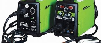
The inverter-type semi-automatic welding machine has a number of features and advantages.
Most users of such welding devices note:
- high installation power;
- mobility of the device;
- ease of maintenance;
- reliability of the inverter design;
- minimum consumption of electrical energy when performing work on welding metal products.
A characteristic feature of inverter welding devices is a more complex electrical circuit compared to transformer or rectifier welding.
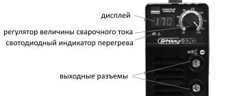
Inverter for welding work.
Repair of inverter welding machines should begin by checking the following elements:
- transistors;
- diode bridge;
- cooling system.
Before you repair welding machines yourself, you need to diagnose the main components. Typically, faulty parts, such as transistors or diodes, can be easily identified by a significant change in geometry.
If such parts can be identified visually, then restoring a welding machine with your own hands will come down to a banal replacement of faulty electrical elements using a soldering iron and solder.
Do-it-yourself repair of semi-automatic welding machines should be carried out by craftsmen who have at least basic knowledge of electronics and know how to use devices such as a multimeter, voltmeter and oscilloscope.
Most models of inverter welding machines come with instructions. It is easier to carry out maintenance of these devices using the diagrams available in the corresponding section of the documentation.
Diagnosis of inverter faults
Immediately before restoring the functionality of inverter welding equipment, you should familiarize yourself with typical faults and the most effective diagnostic methods.
In most cases, repair of semi-automatic welding machines should be carried out according to the following algorithm:
- Visual inspection of all inverter components.
- Cleaning oxidized contacts using a solvent and a brush.
- Studying the design of the inverter using the documentation included in the kit.
- Fault diagnosis.
- Replacement of non-working electronic components.
- Test run.
Functional diagram of a welding inverter.
All malfunctions that may require DIY repair of welding machines are divided into three types:
- arising due to incorrect choice of welding mode;
- arising due to a malfunction of one of the elements of the electronic circuit of the device;
- caused by dust or foreign objects entering the housing of the inverter power supply.
Before checking the welding machine for faulty radio components, you should completely clean it of dust and dirt. Clogging of the cooling elements of the arc support system can adversely affect the performance of many electronic components.
If a preliminary visual check does not reveal any malfunctions, then you should proceed to a more in-depth diagnosis.
Typical reasons for inverter failure are presented:
- liquid entering the inverter housing, resulting in oxidation of the conductive paths and corrosion of the main radio elements;
- an abundance of dust and dirt inside the case, as a result of which the cooling significantly deteriorated and the power microcircuits overheated;
- overheating of the inverter due to the selection of an incorrect operating mode, which may require repair of welding rectifiers.
Repairing a welding transformer, unlike an inverter, can be performed without significant skills and abilities. Transformer assemblies use radioelements that have an incredibly long life cycle.
The repair technique for the converter and other key components of the inverter current source will be shown in the next section.
Main types of breakdowns and their elimination
Before considering the main types of malfunctions of inverter devices, you should familiarize yourself with the inverter device.
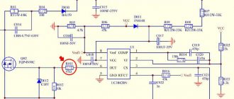
Electrical circuit of a welding inverter.
Most popular models consist of:
- power supply;
- control unit;
- power block.
Malfunctions and repairs of welding machines in most cases are associated with a breakdown of the power unit, consisting of:
- Primary and secondary rectifiers. The block includes two diode bridges of varying power. The first bridge is capable of withstanding up to 40 amperes of current and up to 250 volts of voltage. The second diode bridge is assembled from more powerful elements and is capable of maintaining a current of 250 amperes at a voltage of about 100 volts. Possible errors of this module are associated with failure of the diodes of the primary or secondary bridge.
- Inverter converter. A breakdown of the power transistor of the inverter converter is often the answer to the question why the welding machine does not weld. The inverter can be repaired by replacing the transistor with an analogue one with a current rating of 32 amperes and a voltage of 400 volts.
- High frequency transformer. Typically, a transformer consists of several windings that increase the current to 250 amperes at a voltage of up to 40 volts. Most inverter equipment has two windings made using copper wire or tape.
Before you repair welding machines with your own hands, you should carefully diagnose the device and clearly determine which of the elements is faulty.
You shouldn’t even try to repair an inverter yourself from which thick white smoke is pouring out of the housing. In such cases, the best solution would be to contact a qualified repair center.
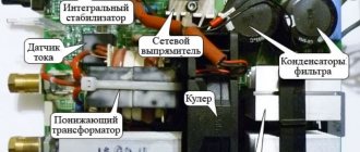
Layout of welding inverter parts.
Repair of a semi-automatic welding machine with an inverter source may be necessary if the following malfunctions occur:
- Unstable burning of a hot arc or strong spattering of the electrode material. The malfunction in most cases is due to the incorrect choice of operating current. The operating instructions say that per 1 millimeter of electrode diameter there should be a current of 20 to 40 amperes.
- Adhesion of welding to metal. This behavior is typical for devices operating at insufficient voltage. Such malfunctions and methods for eliminating them are clearly described in the accompanying documentation. If the electrode sticks to the material being welded, clean the terminal contacts to which the inverter device modules are connected. In addition, it would not be superfluous to measure the voltage in the electrical network.
- No arc when turning on the equipment. The defect is often associated with simple overheating of the device or damage to the power cables during long-term operation at elevated temperatures.
- Inverter emergency shutdown. If during the work the device suddenly turns off, then the short circuit protection between the wires and the housing has probably worked. Repairing the device in the event of such a defect consists of finding and replacing damaged elements of the inverter power circuit.
- Huge consumption of electric current during idle operation. A typical malfunction that occurs due to the short circuit of the turns on the current-carrying coils. Restoring the device's functionality after such a malfunction consists of completely rewinding the coils and applying a layer of additional insulation.
- Switching off welding equipment after a certain period of time. This behavior is typical for overheating inverter electrical appliances. If the welding suddenly turns off, then you need to let it cool down and after 30-40 minutes you can continue working.
- Extraneous sounds when the power supply is operating. Elimination of the defect consists of tightening the bolts holding together the magnetic guide elements. In addition, the malfunction may be due to a defect in the core fastener or a short circuit between the cables.
It is important to note that most types of work should be performed using a soldering iron equipped with a special suction unit. Such a tool greatly facilitates the work of applying and removing solder to the seats of radio engineering elements.
Electrode sticking (arc interruption)
The cause of electrode sticking and arc interruption may be a decrease in voltage due to a short circuit in the transformer windings, faulty diodes or loose connecting contacts. A breakdown of the capacitor filter or short circuit of individual parts to the body of the welding machine is also possible.
Organizational reasons due to which the machine does not weld as it should include the excessive length of welding wires (more than 30 meters).
If sticking is accompanied by a strong hum from the transformer, this also indicates an overload in the load circuits of the device or a short circuit in the welding wires.
One of the repair options to eliminate these effects could be restoring the insulation of connecting cables, as well as tightening loose contacts and terminal blocks.
Recommendations for DIY repairs
Electrical circuit of the welding machine.
When repairing inverter-type welding machines, you should adhere to a certain algorithm:
- If a malfunction occurs, you must immediately disconnect the electrical device from the network, allow it to cool, and only then open the metal casing.
- Diagnostics must begin with a visual inspection of the electrical components of the inverter. There are often cases when repairing an inverter welding machine involves simply replacing damaged parts or soldering conductive contacts. Visually enlarged capacitors or cracked transistors should be replaced first.
- If a visual inspection fails to determine the cause of the malfunction of the welding machine, you must proceed to checking the parameters of the parts using a multimeter, voltmeter and oscilloscope. The most common failures of power units are associated with malfunction of transistors.
- After replacing the electrical elements, it is worth moving on to checking the printed conductors located on the inverter board. If you find torn or damaged tracks on the printed circuit board of a welding tool, you must immediately eliminate the defect by soldering jumpers or restoring the tracks using copper wire of the required cross-section.
- After completing work with the tracks, it makes sense to move on to servicing the connectors. If the inverter device stopped working gradually, then there may be poor contact in the connecting connectors. In this case, it is enough to measure all contacts with a multimeter and clean the connectors with an ordinary household eraser.
- Despite the fact that malfunctions of a welding inverter are rarely associated with diode bridges, it would be a good idea to check their performance. It is better to diagnose this electrical element in a soldered state. If all the legs of the bridge are short-circuited, then you should search for the faulty diode and replace it.
- The last step in inverter repair is checking the board and control panels. Diagnostics of all components of the board should be carried out using a high-resolution oscilloscope.
If the diagnostics have been carried out, but it was not possible to find out what is broken in the welding machine, you should stop doing independent repairs and contact specialized workshops.
When performing independent repair work, you should not forget about the safety rules:
- Do not use electrical appliances without a protective top casing;
- all diagnostic and repair work should be carried out on completely de-energized equipment;
- It is safest to remove accumulated dust and dirt using an air flow generated by a compressor or a compressed gas cylinder;
- Cleaning of printed circuit boards must be done using neutral solvents applied to a special brush;
- Long-term storage of electrical appliances should be done in dry rooms and completely switched off.
Most inverter electrical appliances are supplied complete with accompanying documentation. In these papers you can find a description of the most common faults and repair methods. Therefore, if malfunctions occur, you should carefully study the documentation and only then begin repair work.
The device does not start
In this case, first of all, you need to make sure that there is voltage in the network and the integrity of the fuses installed in the transformer windings. If they are in good condition, you should use a tester to ring the current windings and each of the rectifier diodes, thereby checking their performance.
If one of the current windings breaks, it will need to be rewinded, and if both are faulty, it is easier to replace the entire transformer. The damaged or “suspicious” diode is replaced with a new one. After repair, the welding machine is turned on again and checked for serviceability.
Sometimes the filter capacitor fails. In this case, the repair will consist of checking it and replacing it with a new part.
If all elements of the circuit are in working order, it is necessary to deal with the mains voltage, which can be greatly underestimated and is simply not enough for the normal functioning of the welding machine.