(01/06/2016 23:48)
LM317
is an adjustable voltage and current stabilizer with an output voltage from 1.2 to 37 V. The fact that the input is 21 volts is normal, but the output should be 15 volts. Check the entire LM317 harness and the stabilizer itself. Almost 19 volts is still too much.
Here's another link to help.
8. diggerweb
(01/09/2016 09:57) Your task is to ensure the normal operation of the control board and drivers (you have a device with a TGR?), which are powered by a voltage of 15 volts from the LM317 stabilizer.
I haven’t encountered this particular defect, and here it’s up to you to decide what to do and what to change to what, experiment, just be careful.
It’s better to unsolder the power transistors for the duration of the experiments, first start the stabilizer, check the operation of the control and drivers, and only then solder them in, and then you can’t do it right away, but first like this
.
Most likely the power part has failed, check everything.
47om. which was shunted by this 4D14 zener diode. Next is the transistor 4Q1. It was this transistor that clicked. So much so that there was a burn mark on the 4C2 capacitor and the entire front part of the transistor flew off. Does anyone know what kind of transistor can be put there? Resanta 250. The board says SSB-200-142 Control board 12 pin Shim 3845 and LM324
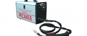
We restore the operation of the welding inverter Resanta SAI-250PN
One day I came across a Resanta SAI 250PN welding inverter. The device, without a doubt, inspires respect.
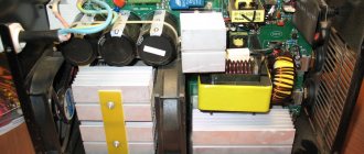
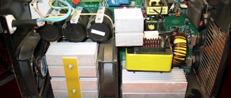
Those who are familiar with the design of welding inverters will appreciate all the power from the appearance of the electronic filling.
As already mentioned, the filling of the welding inverter is designed for high power. This can be seen from the power part of the device.
The input rectifier has two powerful diode bridges on the radiator, four electrolytic capacitors in the filter. The output rectifier is also fully equipped: 6 dual diodes, a massive choke at the rectifier output.
three ( ! ) soft start relays. Their contacts are connected in parallel to withstand the large current surge when welding is started.
If we compare this Resanta (Resanta SAI-250PN) and TELWIN Force 165, then Resanta will give it a head start.
But even this monster has an Achilles heel.
The device does not turn on;
The cooling cooler does not work;
There is no indication on the control panel.
After a quick inspection, it turned out that the input rectifier (diode bridges) were in good condition, the output was about 310 volts. Therefore, the problem is not in the power part, but in the control circuits.
An external inspection revealed three burnt-out SMD resistors. One in the gate circuit of the 4N90C field-effect transistor at 47 Ohms (marked - 470 ), and two at 2.4 Ohms ( 2R4 ) - connected in parallel - in the source circuit of the same transistor.
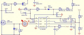
The 4N90C transistor ( FQP4N90C ) is controlled by the UC3842BN . This microcircuit is the heart of a switching power supply, which powers the soft start relay and the +15V integrated stabilizer. It, in turn, powers the entire circuit, which controls the key transistors in the inverter. Here is a piece of the Resanta SAI-250PN diagram.
It was also discovered that the resistor in the power supply circuit of the PHI controller UC3842BN (U1) was also broken. In the diagram it is designated as R010 ( 22 Ohm , 2W ). On the printed circuit board it has the position designation R041. I will warn you right away that it is quite difficult to detect a break in this resistor during external inspection. A crack and characteristic burns may be on the side of the resistor that faces the board. This was the case in my case.
Apparently, the cause of the malfunction was the failure of the UC3842BN (U1) PHI controller. This in turn led to an increase in current consumption, and resistor R010 burned out from a sudden overload. SMD resistors in the circuits of the MOSFET transistor FQP4N90C played the role of a fuse and, most likely, thanks to them the transistor remained intact.
As you can see, the entire switching power supply on the UC3842BN (U1) has failed. And it powers all the main blocks of the welding inverter. Including the soft start relay. Therefore, the welding did not show any “signs of life.”
As a result, we have a bunch of “small things” that need to be replaced in order to revive the unit.
After replacing the indicated elements, the welding inverter turned on, the value of the set current appeared on the display, and the cooling cooler began to make a noise.
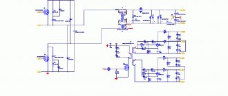
For those who want to independently study the design of a welding inverter, here is a complete schematic diagram of the Resanta SAI-250PN.
The welding machine "Resanta SAI-250" is designed for performing manual electric arc welding using coated electrodes. The inverter is being developed by a company of the same name located in Latvia. The welding machine is assembled in the DPRK, which is reflected in its quality: all parts fit perfectly, there are no gaps, creaks or backlashes.
Schemes of other models
As previously noted, almost all inverters operate on a similar principle, and the created circuits may differ insignificantly. All welding machines are divided into several main groups:
- To carry out electric arc welding when using electrodes coated with a special composition, MMA type equipment is used. This scheme is characterized by high efficiency, and the design is light in weight.
- To use refractory electrodes, MMA+TIG welding equipment is used. They can operate in an environment of inert gases.
- On production lines there are units with semi-automatic bar feeding. In this case, work is usually carried out in an environment of inert gases or in special baths.
- For forging or other repairs, spot welding is used.
The ARC 160 model, the circuit of which is quite complex, can be used for a wide variety of work. Unlike the arc 140, the new model's circuit has no major drawbacks.
Welding inverter TORUS 250
The Torus 250 version consists of the following elements:
- A clock type generator built on a TL microcircuit. It is worth considering that the powerful inverter circuit does not provide for the use of PWM, but the microcircuit has two comparators with thermal protection sensors.
- The protection system and control module are made on the basis of LM. The sensor that determines the current parameters is placed on a ferrite ring with a winding.
- The circuit also includes two output drivers built on IR
A separate category includes a welding inverter circuit using thyristors, which has become very widespread.
Repair of Torus 250 should be carried out by opening the structure and visually inspecting the main elements. In this case they are as follows:
- The output type rectifier is represented by a separate board on which two radiators are placed. They serve as a base for placing diode assemblies. The module also includes one transformer and a choke. The number of elements in the output rectifier largely depends on the specific assembly.
- The switch module is represented by four transistors in each of the four groups. In order to reduce the degree of heating, they are all placed on separate radiators, which are insulated with special gaskets.
- A powerful diode bridge is used as the output rectifier. In the case under consideration, it is located at the bottom of the structure. This model is equipped with an extremely reliable and practical bridge, which is difficult to burn if the cooling system is working properly.
- The control chip is the main design element. As a rule, the durability of the entire device depends on its correct operation. You can check the unit yourself only if you have a special oscilloscope and the appropriate skills to work with it.
- Housing with cooling fan. As a rule, the cooling unit fails only in the event of mechanical impact.
To diagnose many elements, it is necessary to dismantle them. That is why it is best to entrust the work to professionals, since incorrect assembly can lead to significant problems.
The welding inverter SAI 200, the circuit of which differs insignificantly from devices of a similar type, is used for manual arc welding and surfacing when using stick electrodes. RDMMA 200 belongs to a new type of equipment that is created without the use of transformers. Due to this, more accurate and smooth adjustment of current indicators is possible, and there is no strong noise during operation.
In conclusion, we note that the above information determines the complexity of the design of welding inverters. At the same time, manufacturers do not distribute detailed diagrams of devices, which complicates maintenance and repair. Despite the use of a similar circuit when creating almost all inverters, they differ significantly from each other. That is why, before carrying out any work, you need to familiarize yourself in detail with the design features of the device.
Design
On the front panel of the metal body of the Resanta SAI-250 there are power connectors. Indicators are connected to them, with the help of which the network parameters and indication of overheating of the device, welding wires and a regulator for selecting the welding current value are monitored.
The Resanta SAI-250 inverter is equipped with a forced ventilation system, which removes hot air from under the device body through special openings. The welding machine is reliably protected from overheating during operation thanks to such an effective protection system.
An additional protection system automatically turns off the welding machine in the event of a short circuit between the power wires. The user is warned about such an incident by a special warning light that lights up on the instrument panel.
Types of inverter welding current sources
Housing with cooling fan.
Schematic diagram of inverter-type devices In order to understand the essence of the operation of a modern welding unit, it is necessary to know what blocks the schematic diagram of a welding inverter consists of, which provides energy for the short circuit arc during the welding process.
It consists of 2-4 capacitors and a choke.
These situations can occur due to insufficient cooling of power elements at high ambient temperatures, as well as when working in a dusty or too humid atmosphere. Moreover, the use of the latter is now recognized as more reasonable. How does a welding inverter work? Generating a high current that creates an electric arc to melt the edges of the parts being joined and the filler material is what any welding machine is designed for.
This element supplies electric current to the power part of the welding unit. Let's look at the described scheme in a little more detail.
In humid conditions, leaks may occur, which may also cause malfunction. The electrical circuit of the inverter includes the following required components: Power supply unit.
An important step is solving the problem associated with choosing the necessary technology that optimizes the operation of the power unit. The device includes a power transformer. To improve thermal contact, you need to use silicone thermal paste.
If it simply boils, it means that there are shortcomings in the scheme and it is better not to continue the work. Reducing high frequency voltage; 4. Exceptional stability of the voltage supplied to the welding arc is ensured by the automatic elements of the inverter electrical circuit. Therefore, in case of repairs, diodes in the output rectifier should be replaced with high-speed diodes. Repair of welding inverter Resanta 190A. Repair welding inverter 190A Resanta does not turn on
Special inverter functions
The effectiveness and ease of use of “Resanta SAI-250” is largely due to two important functions: “Hot start” and “Anti-sticking”.
The ignition of the electric arc of the welding machine occurs instantly thanks to the first function, implemented by automatically increasing the strength of the welding current, which saves the user from additional actions. The “Anti-stick” function automatically reduces the welding current when the electrode sticks to the metal surface when the arc is ignited. After eliminating such sticking, the inverter increases the current to the set value. Both functions are very useful and easy to use, which is confirmed by the reviews left about the Resanta SAI-250 welding machine.
Inverter Features
The welding machine is intended for use for domestic purposes, since the “Resanta SAI-250” circuit and its design ensure reliable and safe operation even with significant surges and surges in voltage. The inverter allows manual arc welding even at minimum voltage.
The maximum diameter of electrodes that can be used when working with Resanta SAI-250 is 6 mm. The current strength is adjustable over a wide range, but the upper limit is 250 A. The welding machine can withstand high loads for a long time thanks to protection systems. In terms of its characteristics, the Resanta inverter outperforms many similar models of welding machines offered on the market.
The inverter no-load voltage is 80 V. Built-in IGBT series transistors guarantee a long service life of the welding machine even if it is used frequently and under high loads. The protection level of this inverter model is IP21.
The mobility and compactness of the Resanta SAI-250 greatly facilitates its use. A convenient handle located on the inverter body allows you to quickly and easily carry it from place to place around the work site. Reviews of the Resant SAI-250 note the accuracy and ease of setting all parameters. The advantage of the device is that even with significant voltage surges, all specified settings remain unchanged.
Specifications
The inverter has the following technical parameters:
- The welding machine can be operated at temperatures from -10 to +400 degrees.
- The maximum consumption current is 35 A.
- The operating welding current is adjusted within the range of 10–250 A.
- The voltage of the welding arc generated by the inverter of this model is 30 V.
The welding machine operates both from a centralized electrical network and from a gasoline generator with a power of at least 5 kW. When choosing electrodes for welding, it is necessary to take into account the fact that when the input voltage decreases, the welding current also decreases.
Swaris device diagrams
The welding machine Svaris 200 is characterized by ease of use and low cost. Already the Swaris 160 models had high performance characteristics, and the new version was improved. The circuit of the inverter welding machine determines the following operational characteristics:
- The maximum consumption is 5 kW.
- Welding current can vary from 20-200 A.
- The open circuit voltage indicator is 62 V.
- Efficiency rate 85%.
- Recommended electrodes 1.6-5.0.
In general, we can say that the inverter is made according to the classical scheme, which was discussed above.
Preparing the device for operation
It is not difficult to prepare the Resanta SAI-250 inverter for operation - you must follow a certain sequence of actions in order to prevent emergency situations from occurring. First of all, a grounding negative wire and a wire with an electrode holder are connected to the device. After this, the minimum level of welding current is set using the regulator. The inverter is connected to the electrical network and starts only after these steps have been completed.
In the operating instructions for the welding machine, the manufacturer indicated the current required for a specific type of electrode.
After all welding work is completed, the inverter is again set to the minimum current value, after which the device is turned off and disconnected from the electrical network. The cables are disconnected from the device only after it is de-energized.
Safety precautions when operating welding equipment
Before starting operation, it is advisable to leave the inverter in a room at a positive temperature for several hours. This precaution will avoid the formation of condensation in the device, which can cause a short circuit. In addition, it is necessary to monitor the integrity of the insulation of the welding cable and connection wires. Damage to the insulating layer not only contradicts safety requirements, but can also cause the device to fail.
The Resanta inverter cannot be used in rooms where work is carried out, accompanied by the formation of small metal shavings and dust. Such inclusions can get inside the device and damage it. Also, do not use the inverter outdoors during rainfall or in rooms with high levels of air humidity.
When working with welding equipment, it is advisable to adhere to several basic rules:
- The place where welding work will be carried out must be well ventilated and have access to fresh air.
- Fire safety rules must be taken into account.
- During work, be sure to use special protective clothing, a welder’s mask, a hat and thick gloves. Such products will help protect your skin and eyes from burns.
Is it possible to independently repair a welding inverter?
Both domestic and foreign experts note the long service life of the Resanta SAI-250 welding machine. Active operation of the inverter, subject to safety precautions and all relevant requirements, can continue for years, however, like any other equipment, it requires regular repairs.
It is worth noting that both unscheduled and preventative repairs of such equipment are best left to specialists. Numerous authorized workshops service welding equipment of this brand. However, the user can perform simple repair work independently.
Such repair work is most often carried out in cases where the inverter overheats, as indicated by the indicator located on the front panel. It is easy to fix this problem - just clean the internal surfaces of the welding machine from dirt and dust.
Poor, unsatisfactory operation of the welding inverter, reduced power can be associated with low voltage of the electrical network or the use of wet electrodes. The problem of reduced device power associated with damp electrodes can be eliminated easily and quickly: you must thoroughly dry all the electrodes.
Schemes of models MMA-200 and MMA-250
The MMA-200 and MMA-250 models are widely used. These inverters are almost identical, the only difference is the following points:
- The MMA 250 welding inverter circuit provides for the presence of 3 field-type resistors in the output stage. All are connected in parallel. The MMA 200 welding inverter circuit indicates only the presence of two resistors.
- The new version has three pulse transformers, while the old one only has two.
The basic design of both models is almost completely identical.
MMA-200 inverter circuit