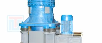
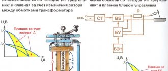
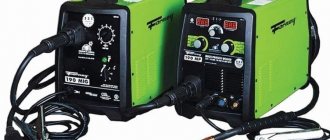
In the twentieth century, the AC welder was the most common metal welding device in construction and industry. This is explained by the simplicity of the design of the device.
In short, it is a power step-down transformer, the secondary winding of which has several terminals. Depending on what kind of metal needs to be welded, what thickness, what electrode, the welder chooses one or another output of the secondary winding.
General information about the device
Nikola Tesla's greatest discovery is used by humanity everywhere today. Most appliances in every home are designed to run on DC power, but outlets supply AC power. This is why you almost always need a special device or rectifier that will convert AC to DC.
The inverter performs a completely opposite function. You can consider its work using the example of a regular flashlight. The device is small and is powered by a built-in battery, which becomes a direct current source. If you remove it from the device, turn it over with the other pole and install it again, there will be no noticeable difference in operation or quality of lighting. However, electricity will flow differently.
This process can be compared to a mechanical converter, where human hands turn the battery at a speed of 50-60 times per second. Of course, devices that can be purchased in specialized stores work somewhat differently. Magnetic switches are used to constantly change the direction of electron flow. However, this design is only for mechanical devices.
Electronic inverters change direction smoothly, eliminating sudden voltage changes. The second type is considered a more preferable option, since constant voltage surges negatively affect the functioning of some electrical appliances. The design of such inverters is equipped with special inductors and capacitors. These parts soften the flow of energy at the input and output, thereby creating a smooth power source for electrical appliances.
In some cases, inverters are used for transformers to convert an AC source to a higher or lower frequency depending on the needs of a particular consumer. It is worth noting that the output power is always less than the input power. This is necessary for the normal functioning of the devices. Any transformer or inverter cannot supply more energy than it consumes, since some of it is wasted.
Devices on transformers
The first models of permanent welding machines were a development of alternating current devices. In addition to the welding transformer, a diode rectifier made according to a bridge circuit was mounted at the output of the secondary winding, then powerful capacitors were connected to reduce ripple and a choke to obtain a more stable arc.
From a single-phase or three-phase network, alternating voltage was supplied to the primary winding of the step-down transformer. At the output of the secondary, a voltage of about 70 V was obtained at idle, then it went to the rectifier and welding electrode.
When the electrode was shorted to ground and then separated for a short distance (approximately 5 mm), an electric arc occurred. The welder had to move the electrode along the future seam at the speed necessary to form a weld pool.
How does an inverter-type welding machine work?
Due to its technical characteristics, the inverter can be used to perform welding with various types of electrodes. This device is distinguished by its compact size and light weight, which makes it very mobile, unlike heavy and large transformers. It is also convenient that such a welder can generate both direct and alternating current.
In order to understand what advantages an inverter has, you need to understand how it works. The operation of this device, which began to gain mass popularity only at the beginning of the 21st century, is based on a completely different principle compared to the operation of a conventional welding transformer.
Schematic diagram of the welding inverter "Duga-200" (click to enlarge)
The alternating current supplied to the inverter from a regular electrical network is first rectified by passing through a diode bridge, which is equipped with the electrical circuit of the device. After rectification, the direct current is supplied to power transistors, which convert it back into alternating current, but with an increased frequency. To reduce the voltage of high-frequency alternating current and obtain the welding current of the required strength, a transformer is used in the electrical circuit of the inverter.
Since the voltage reduction of high-frequency current is not carried out according to the same principle as in a conventional welding machine, there is no need to use large transformers for this; a compact device is quite sufficient. After reducing the voltage and increasing the current to the required value, it is supplied to the output rectifier, in which it is converted to constant.
Inverter controls using the example of the Fast and the Furious device (click to enlarge)
The use of high-frequency current generated by the inverter not only makes it possible to significantly reduce the dimensions of the device, but also has a positive effect on the combustion process of the welding arc, which is highly stable. Such a welding machine is characterized by high efficiency, since it does not waste energy on heating the transformer iron.
Simplified diagram of the operation of a welding inverter
Thus, any inverter device consists of such structural elements as:
- a rectifier assembled on the basis of a diode bridge (this electrical circuit block is responsible for rectifying the alternating current coming from the electrical network);
- the inverter itself, which is a generator of high-frequency electrical pulses (the basis of this unit is made up of transistors that open and close at high frequencies);
- a step-down transformer, which solves the problem of lowering the high-frequency voltage and, accordingly, increasing the welding current;
- high-frequency output current rectifier (such a rectifier, like the input unit, is assembled on the basis of a diode bridge);
- a special electronic unit designed to control the operating modes of the inverter apparatus.
Content
- What is polarity?
- Welding with different currents
- Which electrode should I use?
If you have worked with welding before or are at least somewhat familiar with it, then you have most likely heard the terms “AC” and “DC”. AC and DC are different types of currents that are used in the welding process. Because welding uses an electric arc to create the heat necessary to melt the metal, it requires a stable current with varying polarities depending on the material being welded.
To make a high-quality weld, you first need to understand what these two currents mean on the welding machine, as well as on the electrodes.
But first: what is the difference between AC and DC welding?
DC and AC welding refers to the polarity of the current passing through the machine's electrode. AC stands for alternating current and DC stands for direct current. The strength and quality of the weld will depend on the polarity of the electrode.
Types of electricity
Most teachers who provide students with information about electricity talk primarily about direct current (DC).
It is a stream of electrons that follow each other at a certain distance. The most popular analogy from experienced teachers is the comparison of a stream with ants walking in a column and carrying ordinary dry leaves. This idea is quite general, but the basic idea is correct. The circuit resembles a continuous electrical loop that powers a regular flashlight. However, electricity works differently in larger appliances. Wall-mounted outlets provide an alternating current (AC) power source to appliances. In it, electricity switches at a high speed of 50-60 times per second, that is, the frequency of such switchings is 50-60 Hz.
It is not entirely clear to an ordinary person who does not have knowledge in the field of electronics how such a current powers devices if it constantly changes the direction of its movement. However, the answer to this question is simple. For example, you can take a regular wall lamp that runs on AC power. When you plug it into a power outlet, the electrons begin to actively move, change places and change the direction of movement. The whole process happens very quickly, so heat is generated in the wires.
It is this heat that will pass into the lamp, causing it to glow. Alternating current powers devices just as efficiently as direct current, but the electrons in it move in place.
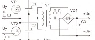
Voltage inverter circuit
The most common voltage inverter circuit consists of four IGBT transistors VT1...VT4, connected in a bridge circuit, and four freewheeling diodes, designated VD1...VD4, connected in parallel to controlled semiconductor switches in the opposite direction. The converter powers an active-inductive load. It is the most common one, so it was taken as a basis.
The inverter input terminals are connected to Uip. If such a source is a diode rectifier, then its output is necessarily shunted by capacitor C.
In power electronics, transistors with an insulated gate IGBT (they are shown in the diagram) and GTO, IGCT thyristors are most widely used. When operating with lower powers, MOSFET field-effect transistors have no competition.
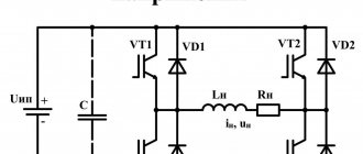
At time t1, VT1 and VT4 open, and VT2 and VT3 are closed. A single path is formed for the current to flow through the load: “+” Uip – VT1 – load RнLн – VT4 – “-” Uip. Thus, in the time interval t1 - t2, a closed circuit is created for the flow of in in the corresponding direction.
Circuit operation mode
To change the direction of in, control pulses are removed from the bases VT1 and VT4 and signals are sent to open the second and third VT2,3. At point t2 on the t time axis, the first and fourth VT1,4 are closed, and the second and third are open. However, since the load is active-inductive, it cannot instantly change direction to the opposite. This will be prevented by the energy stored in the inductance Lн. Therefore, it will maintain the same direction until all the energy stored in the inductance in the form of a magnetic field, equal to Wм = (Lн∙i2)/2, is dissipated.
In this regard, in the time interval t2 - t3, the current will flow through diodes VD2 and VD3, maintaining the same direction to RнLн, but will pass in the opposite direction through U or capacitor C if the energy source is a diode rectifier. Therefore, it is necessary to install capacitor C if the converter is connected to a diode rectifier. Otherwise, the flow path will be interrupted, resulting in a strong overvoltage that can damage the consumer insulation and damage semiconductor devices.
At time t3, all the energy stored in the inductance will drop to zero. Starting from moment t3 to moment t4, under the influence of the applied Uip, through the open semiconductor switches VT2 and VT3, in will flow through LnRn in the other direction.
At point t4, located on the t time axis, the control signal from VT1,3 is removed, and VT1 and VT4 are opened. However, in continues to flow in the same direction until the energy stored in the inductance is consumed. This will happen in the time interval t4 – t5.
Circuit operation
Starting from moment t5, in changes direction and flows from Uip through LнRн along the path through VT1 and VT4. Further, all processes occurring in the electrical circuit will be repeated. On LnRn, the voltage shape will be rectangular, but the current on the active-inductive load will have a sawtooth shape due to the presence of inductance, which does not allow it to instantly rise and fall. If the consumer is purely active in nature (inductance and capacitance are practically equal to zero), then the shapes in and un will be in the form of rectangles.
Since VT1...VT4 were opened in pairs throughout the entire length of the corresponding half-cycles, the maximum possible in was formed at the output of the converter, therefore, in of the maximum value flowed through LnR. However, it is often necessary to ensure a smooth increase in power at the consumer, for example, to gradually increase the brightness of lighting or the engine speed.
It should be clarified that the signals coming from the control system of the control system are not sent directly to the bases of the semiconductor switches, but through the driver. Since modern control systems are built on meringue microcontrollers that produce low-power signals that are not capable of opening an IGBT, an intermediate link – a driver – is used to increase the power of the opening pulse. In addition, the driver often performs many additional functions - it protects the transistor from short circuits, overheating, etc.
Inverter UPS
The vast majority of electrical appliances in Russia that modern people use every day are designed for a voltage of 220V-230V.
Chemical voltage sources, batteries capable of storing a charge of electricity for a long time, provide a constant voltage that is too low to power household appliances: 2 volts, 6 volts, 12V, etc. Inverters convert direct voltage from batteries into alternating voltage 220V or 230V, depending on the design and settings. The work of all UPSs is based on this!
Video what is an inverter uninterruptible power supply and how it works
The battery life of the uninterruptible power supply will be proportional to the number and capacity of the batteries connected to the inverter input. But there are other factors that affect the operating time - you can read more here.
Batteries can store a supply of electrical energy for a long time, which allows you to keep a large amount of accumulated electricity in reserve for emergency situations, accumulated in the battery.
If there is a loss of electricity at the input to the distribution board, the inverter automation will instantly transfer the power of the electrical appliances connected to the inverter output to the battery (through an electronic circuit that converts a direct voltage of 12 Volts into an alternating voltage of 220 V with a given frequency (Hz)).
There is no switching in online systems - You can read more here.
The main advantages of electric inverters:
- This is environmental safety (no harmful environmental pollution)
- Low noise during operation, have a low noise level of the cooling fan several times compared to power plants...
- They do not require refueling or constant maintenance.
- They have high efficiency and low operating costs, tied to the cost of electricity.
- Continuous power supply, no pause (as in power plants) when switching to batteries.
- Possibility to increase battery life by increasing the number of batteries.
Main applications of inverters:
1) UPS for boilers (UPS for gas boilers)
2) UPS for pumps (UPS for long standby time)
3) Uninterruptible power supply for alarm and video surveillance systems (UPS for alarm and video surveillance systems)
Application example in a private home:
Consider the ECOVOLT PRO 1012 model.
A load power of 1000 W with a parameter value of cos = 0.8 allows you to connect electrical equipment with a total power of 1 kW.
An approximate calculation of the load power could be as follows:
- Gas boiler with piping – 300 W.
- Circulation pump 70 W,
- Emergency lighting – 300 W,
- TV – 200 W
(power values of electrical appliances may differ from those given here; exact values can be obtained from the equipment passport).
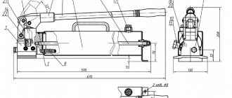
How to make the most convenient transformer for welding: practical tips
Theoretically, you can use any model of transformer to power the welding machine. The main requirements for it:
- provide arc ignition voltage at idle speed;
- reliably withstand the load current during welding without overheating the insulation from prolonged operation;
- meet electrical safety requirements.
In practice, I have come across different designs of homemade or factory-made transformers. However, they all require electrical engineering calculations.
I have been using a simplified technique for a long time, which allows me to create fairly reliable transformer designs of medium accuracy class. This is quite enough for household purposes and power supplies for amateur radio devices.
It is described on my website in an article about making a transformer soldering iron Moment with your own hands. This is an average technology. It does not require clarification of the grades and characteristics of electrical steel. We usually don’t know them and cannot take them into account.
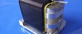
Features of core manufacturing
Craftsmen make magnetic wires from electrical steel of various profiles: rectangular, toroidal, double rectangular. They even wind coils of wire around the stators of burnt-out powerful asynchronous electric motors.
We had the opportunity to use decommissioned high-voltage equipment with dismantled current and voltage transformers. They took strips of electrical steel from them and made two donut rings out of them. The cross-sectional area of each was calculated to be 47.3 cm2.
They were insulated with varnished cloth and secured with cotton tape, forming a figure of a reclining figure eight.
They began to wind the wire on top of the reinforced insulating layer.
Secrets of the power winding device
The wire for any circuit must have good, durable insulation, designed to withstand long-term operation when heated. Otherwise, it will simply burn during welding. We proceeded from what was at hand.
We received a wire with varnish insulation, covered with a fabric sheath on top. Its diameter - 1.71 mm is small, but the metal is copper.
Since there was simply no other wire, they began to make the power winding out of it with two parallel lines: W1 and W'1 with the same number of turns - 210.
The core donuts were mounted tightly: this way they have smaller dimensions and weight. However, the flow area for the winding wire is also limited. Installation is difficult. Therefore, each power half-winding was separated into its own magnetic circuit rings.
In this way we:
- doubled the cross-section of the power winding wire;
- saved space inside the donuts to accommodate the power winding.
Wire alignment
You can get a tight winding only from a well-aligned core. When we removed the wire from the old transformer, it turned out to be bent.
We figured out the required length in our minds. Of course it wasn't enough. Each winding had to be made from two parts and spliced with a screw clamp directly on the donut.
The wire was stretched along its entire length on the street. We picked up the pliers. They clamped the opposite ends and pulled with force in different directions. The vein turned out to be well aligned. They twisted it into a ring with a diameter of about a meter.
Technology of winding wire on a torus
For the power winding, we used the rim or wheel winding method, when a large-diameter ring is made of wire and wound inside the torus by rotating one turn at a time.
The same principle is used when putting a winding ring on, for example, a key or keychain. After the wheel is inserted inside the donut, they begin to gradually unwind it, laying and fixing the wire.
This process was well demonstrated by Dmitry Volzhsky in his video “Winding the primary winding of toroidal transformers.”
This work is difficult, painstaking, and requires perseverance and attention. The wire must be laid tightly, counted, the process of filling the internal cavity must be monitored, and the number of turns wound must be recorded.
How to wind a power winding
For it, we found a copper wire of a suitable cross-section - 21 mm2. We estimated the length. It affects the number of turns, and the no-load voltage necessary for good ignition of the electric arc depends on them.
Typically reference books recommend 60-70 volts. One experienced welder told us that in our case 50 would be enough. We decided to check it, and if it wasn’t enough, then increase the winding further.
We made 48 turns with the middle terminal. In total, there were three ends on the donut:
- middle - for direct connection of the “plus” to the welding electrode;
- the outer ones - to the thyristors and after them to ground.
Since the donuts are fastened together and the power windings are already mounted on them along the edges of the rings, the winding of the power circuit was carried out using the “shuttle” method. The aligned wire was folded like a snake and pushed through the holes of the donuts for each turn.
The middle point was unsoldered using a screw connection and insulated with varnished cloth.
Principle of operation
The inverter operates on a simple principle, which can be understood by giving a specific example.
A conventional battery operates primitively and produces a constant flow of current that does not change its direction. If you add a switch to this design, which at the output will change the direction of electron movement, then AC will flow to the device. To make it correct, the switch must work properly and operate at least 50 times within a second. About 3,000 changes in the flow of electrons occur per minute. A mechanical inverter works somewhat differently and, using special magnets, also quickly changes the direction of the current. The principle of its operation is reminiscent of a doorbell. When a button is pressed, a person acts on a spring, which sends a signal to change the power and flow of electricity. When released, everything returns to its original position. The device is also equipped with a special controller that performs other functions:
- voltage regulation in the device;
- switching frequency synchronization;
- providing protection against overloads and breakdowns.
Thanks to this, even the mechanical model of the device allows large electrical appliances to operate uninterruptedly.
Advantages and disadvantages of inverters
The high popularity of inverters is explained by a number of advantages that they have.
- Inverters are distinguished by high power and a wide range of welding current regulation. — Even when the work is performed by a not very highly qualified specialist, inverter devices make it possible to obtain welds of high quality, reliability and attractive appearance.
- Inverters are compact in size and light in weight. — Devices of this type have high efficiency and, as a result, consume electrical energy economically.
- During welding with an inverter, the molten metal is splashed very slightly, which helps to save consumables and form neat welds.
- The versatility of inverter machines is undeniable, thanks to which they can be used to perform welding using different technologies.
Inverters also have disadvantages, the most significant of which include the following.
- Inverters are quite expensive when compared to conventional welding transformers.
- If they fail, inverter devices are very expensive to maintain.
- Inverters, whose design is based on complex electronic circuits, react very critically to dust, high humidity and low temperatures. That is why the scope of use of such devices is quite limited. For their trouble-free operation, it is necessary to create special conditions and devote a lot of time to their maintenance (cleaning from dust, etc.).
- Complete with inverter devices, wires whose length does not exceed 2.5 meters can be used. Such short wires are also factors that seriously limit the application range of inverters.
Overall, if you weigh the pros and cons of using inverters for welding, the benefits will be significantly greater. The design of the equipment ensures rapid ignition of the welding arc and its stable combustion during the work process, and thanks to its technical capabilities, inverters make it possible to obtain high-quality, reliable and accurate connections with electrodes of any type.
What is a regular welding machine?
The classic current source for generating an electric arc is a transformer. The welder lowers the mains voltage, and the current increases accordingly. Such equipment was used for manual welding everywhere until the beginning of the 21st century.
The operating principle of the transformer is based on the magnetic induction method. Electric current passing through the first winding magnetizes the core. An electromagnetic field arises, and under the influence of waves an electric current is formed in the wire of the secondary transformer winding. The output voltage depends on the number of secondary turns. The equipment generates high-ampere current with parameters necessary for welding.
Welding transformer layout
Advantages and disadvantages of welding transformers
First, about the advantages of transformer devices:
- simplicity of the device, the scheme of operation is clear to the student;
- maintainability, in case of breakdown the transformer can be repaired independently;
- the ability to work for a long time is ensured by low sensitivity to overheating during operation;
- impact resistance – the risk of mechanical damage during transportation is minimal;
- accessible service;
- low price;
- versatility, the device is used for welding various metals;
- there are no special storage requirements, the transformer is resistant to high humidity and dust.
The disadvantages of traditional welders are obvious:
- when the network sags, the transformer turns off; a stable voltage is needed for power supply;
- lack of precise adjustment of current parameters, large adjustment steps, difficult to set up equipment for welding thin-walled workpieces;
- heavy weight, it is difficult to move the equipment independently;
- significant dimensions;
- high power consumption.
It is worth considering that most transformers operate from a three-phase network. Beginners working with a transformer have problems with arc ignition and sticking. Seams are difficult to form without experience.
Automotive inverters
Voltage converters with a modified sine wave (quasi-sine), often called car inverters, allow you to connect not very precise equipment that does not have electronics and control circuits, such as a drill, grinder, light bulbs and other devices of this kind. They have a fairly low efficiency and high current consumption for their own needs, and for the most part are designed for a short time of continuous operation.
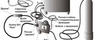
Simple design of DC welding machine
Based on the installation principle, the following parts can be distinguished:
- homemade transformer for welding;
- its power supply circuit is from network 220;
- output welding hoses;
- power unit of a thyristor current regulator with an electronic control circuit from a pulse winding.
Pulse winding III is located in power zone II and is connected through capacitor C. The amplitude and duration of the pulses depend on the ratio of the number of turns in the capacitor.
Pure sine inverters
Inverters with pure sine wave allow you to connect any devices, since they have the correct voltage form at the output, which allows you to connect any equipment and devices without the risk of failure, so most often these inverters are used in homes to organize backup power. You can connect pumps, energy-dependent heating boilers with electronics, modern refrigerators and other household appliances to them. Without having a negative impact on her work. Often these devices combine the functions of an uninterruptible power supply (UPS) and an inverter. Those. When the central power grid is turned off, the devices connected to it are automatically switched to battery power in a fraction of a second. Without interrupting the operation of connected devices.
Voltage inverter with regulation of output parameters
The easiest way to change the value of un is to regulate the value of the supplied Uip, if such a possibility exists. For example, for an adjustable rectifier this is not a problem. But such sources of electrical energy as a battery, supercapacitor or solar battery do not have this capability. Therefore, regulation of the frequency and value of the output un is entirely the responsibility of the inverter.
To regulate the value of u, one pair of diagonally opposite transistors should be opened somewhat earlier than in the case discussed above. Therefore, the control system algorithm should provide for a shift of control signals. For example, VT1 and VT4 are applied to open relative to the control pulses supplied to the bases VT2 and VT3, at a certain angle called control angle α.
Please note that the amplitude value of un remains unchanged and is approximately equal to the value of Uip, but the effective value of un will decrease as the control angle α increases. Let's look at how this works.
In the time interval from t1 to t2, a pair of transistors VT1 and VT4 is open; in flows from right to left, as shown in the diagram. At moment t2 the first transistor closes and the second opens. The current remains in the same direction, and the load turns out to be short-circuited, as a result of which the voltage across it drops to almost zero, and iin decreases accordingly.
Next, a command is received from the control system and VT2 opens and VT4 closes. However, the energy accumulated in the inductance does not allow the current in to change its direction, and it flows through the same circuit, only through diodes VD2 and VD3 opposite the power source. The duration of this process continues until time point t4. At point t4, under the influence of the applied Uip, in changes sign to the opposite.
Pulse width modulation
This algorithm for the operation of semiconductor switches, in contrast to the previous algorithm, forms a pause of a certain duration, which ultimately leads to a decrease in the effective value of un. To form a sinusoidal shape, pulse-width modulation PWM is used. We will consider the converter with PWM, or rather the algorithm of its operation, which includes PWM, separately.
It should also be noted that the considered algorithm for controlling semiconductor switches is called pulse-width WID control, which is often confused with PWM, although the difference is huge.
In converter technology, PWM has practically replaced WID, since it has a number of positive properties that increase the efficiency of the entire device and reduce the level of electromagnetic interference. Therefore, in the future we will consider a voltage inverter with PWM.
Inverter characteristics
In addition, in addition to the form of the output voltage, inverters differ in the power of the devices connected to them, which is an equally important characteristic. Therefore, it is worth calculating in advance the power of all equipment that is planned to be powered by the inverter. It should not exceed the rated voltage of the inverter, but it is better that it be 15-20 percent less. This will extend the service life of the inverter, because it will not work at extreme conditions. It is also worth paying attention to additional functions, such as sleep mode, which will increase battery life and other features of a particular model. A necessary option would be the presence of a cold start, i.e. charge the battery when voltage appears at the input, when the battery is completely discharged, not all devices can do this. Some devices additionally install a solar panel controller, which allows you to connect panels to them and charge the batteries from solar panels. There are two types of controllers: PWM and MPPT; it is better to choose the latter, because they have greater efficiency and allow you to collect more energy under equal panel power and weather conditions. It is also worth paying attention to the power of the controller; the number of solar panels that can be connected to it will depend on this. They are called solar inverters. Online type inverters are double conversion inverters. It has a built-in rectifier that converts alternating current from the mains at the input into direct battery current, and at the output converts it back into alternating current for further consumption. In inverter mode, when a network break occurs, energy is also taken from the battery. These devices have the best characteristics in terms of voltage waveform, surge suppression, and network-to-battery switching speed. Network inverters convert the sun's energy and send it directly to the consumer's network, work without batteries, and serve to save electricity consumption. There are also a large number of inverter manufacturers, and before purchasing, you should study reviews and find out the availability of nearby service centers and warranty conditions for specific inverters. Most of the inverters are domestic and Chinese, and both have decent models. But models with a Russian name are not always produced in Russia; they are often also assembled in China.
More and more people are purchasing inverters as autonomous and backup power sources in order to protect themselves from frequent power outages, as well as obtaining 220V electricity at sites not connected to the central network, but where it is needed at certain times, using batteries. The IC EnergoPartner company offers a large selection of inverters of various types and modifications, from low-power automotive inverters to pure sine-wave inverters, high power, with many additional functions and settings. All devices are certified, have a warranty and a wide network of service centers throughout the Russian Federation. You can also choose different types of batteries for connection to the inverter.
Which inverter to choose for home use
To choose a suitable welding inverter, you must first decide what it is supposed to do and under what conditions it will be used.
Based on these data, it is already possible to select power, operating modes and other technical characteristics of the future device. A home craftsman for household needs is unlikely to require such types of welding as MIG/MAG and TIG, so further we will talk only about manual MMA electric arc welding. In order to qualitatively weld angles, channels, strips and pipes up to 5 mm thick, theoretically, a welding inverter with the following characteristics is sufficient:
- mains voltage - 220 V;
- maximum welding current - 120÷150 A;
- PV - 40÷50%;
- electrode thickness - up to 4÷5 mm.
But in practice, the operation of the inverter will most likely occur under conditions different from the standard ones. Therefore, you will almost certainly have to adjust the selected characteristics. First of all, you should analyze the quality and stability of the supply voltage. Typically, welding inverters are designed to operate in conditions of input voltage fluctuations of ±10÷15%, so when connected to an electrical network with such parameters, they will work without any problems. If the deviation reaches 30% (which often happens in dachas, garages and rural areas), then you should choose an inverter model with the ability to operate at reduced voltage.
It must be remembered that the inverter power and welding current will drop in proportion to the decrease in voltage. It should also be taken into account that the use of welding wires longer than five meters (which will certainly be required when welding outdoors) also reduces its power. Therefore, it is necessary to choose a device with a current reserve. In our case, the optimal device would be a maximum current of 160÷180 A.
A home inverter should be lightweight so that it is easy to carry, and compact so that it fits in the trunk of a car. It is advisable to choose an inverter with a shock-resistant and waterproof housing, as well as a transparent protective cover for the control panel. The presence of a digital indicator is desirable, but not necessary, since on inexpensive models they often work with large errors.
Almost all modern inverters (even in the price category up to 10 thousand rubles) are standardly equipped with the Arc Force, Anti stick and Hot start functions. But when choosing a specific model, you should still make sure that these modes are available.
Figure 8 - Welding process
The technical requirements for choosing the best home welding inverter in our version will look something like this:
| № | Name | Household |
| 1 | Input voltage (V) | 220 |
| 2 | Allowable voltage fluctuations (%) | +15 / -40 |
| 3 | Power, kWt) | 4÷5 |
| 4 | Max. and min. operating current values (A) | 10÷180 |
| 5 | Open circuit voltage (V) | 60÷80 |
| 6 | Degree of protection | IP-22 |
| 7 | Electrode diameter (mm) | 1.6÷5.0 |
| 8 | Duration of switching on (duty cycle, %) | 30÷50 |
| 9 | Additional functions | Arc Force, Anti stick, Hot start |
| 10 | Weight, kg) | 4÷5 |
When choosing a specific model, you should focus on well-known brands that have been on the market for at least ten years. It is also necessary to pay attention to the proximity of the service center and the warranty period, which for inverter manufacturers ranges from one to five years.
Device classification
There are many models of inverters.
They can be massive and equipped with special batteries. Portable models are available that are small in size and used for various purposes. Devices are also divided according to the power they consume and produce. This parameter is considered the main one when choosing, especially if a high indicator is needed, for example, in production. It is worth noting that even the most powerful inverters are not designed to operate at maximum performance for a long time. Depending on the principle of operation, devices are divided into the following:
- dependent ones that work only from the network;
- autonomous, equipped with a battery;
- voltage and current inverters.
Autonomous models are usually used for short-term operation and do not depend on a current source. Some devices are designed specifically for permanent connection to the network. Sometimes devices are equipped with solar panels.
Each option has its own advantages. For example, autonomous ones are suitable for any device and can help out in a difficult situation. Solar saves electricity, and dependent ones do not need recharging or other conditions to function. At night, the solar battery is inappropriate and will not serve the owner, so such models are rarely chosen.
There are also universal devices that can work online and offline, but not at the same time. The disadvantage of such devices will be their large size, since to ensure operation in two modes it is necessary to equip the unit with additional parts.
Devices that were installed before 1970 used special mercury-arc valves. Modern models are usually solid-state and are considered more efficient and safe.
Types of welding machines depending on the type of welding
Having considered what types of welding machines there are by type of power source, let’s move on to their varieties according to welding modes.
Devices for manual arc welding MMA
These types of welding machines are built on the basis of inverters, transformers or rectifiers. The welder operates a holder on which the consumable electrode is fixed. The metal rod closes the arc on the workpiece and serves as a filler material. The outer coating, when melted, creates a gas cloud to protect the weld pool from the external environment.
Manual arc welding machine - MMA.
Application. This type of welding can join ferrous metals. If you install electrodes with a stainless steel rod, you will be able to weld alloy steel. But the speed of work is slow, you need enough experience to get a high-quality connection, and you constantly have to control the arc length as the electrode decreases.
Diagram of the electric arc welding process.
Watch a video about MMA welding machines:
Machines for semi-automatic MIG/MAG welding
MIG/MAG welding is called semi-automatic because the seam is made using a torch, but the wire inside is fed from a special mechanism from a reel. The principle of operation is similar to MMA, only instead of a holder there is a compact torch. The metal is connected by an electric arc (the ground cable is connected to the product, and the “plus” remains on the wire).
Semi-automatic welding machine - MIG/MAG.
Application. Thanks to the continuous supply of additive, long, neat seams can be created. There is no slag in the weld pool, so it is better for the welder to control it. Protection from the external environment is provided by gas supplied from the cylinder through the burner nozzle. This type of welding is fast and allows you to join metal with a thickness of 0.6 to 20.0 mm. Depending on the type of wire being installed, ferrous metal, stainless steel, and aluminum can be welded. But you need to carry a cylinder with you. Even when there is wind and work outside, the weld pool becomes defenseless (the supplied gas is blown away).
Diagram of the semi-automatic welding process.
Watch a video about semi-automatic MIG/MAG welding machines:
TIG welding machines
TIG welding is performed using inverters. There is also an electric arc here, but it burns between the product and a non-consumable tungsten electrode. The latter has a diameter of 1.6-3.2 mm and is sharpened in the form of a sharp cone. This allows you to create narrow seams. Connections can be made using only the edges being fused, or using an additionally supplied additive with the welder’s free hand. The weld pool is protected by argon blown from the torch nozzle.
Tig welding machine.
Application. When working with direct current, you can weld ferrous metals and stainless steel. There are types of welding machines with AC/DC function designed for welding aluminum. With such equipment you can cook very carefully and economically, but the speed of the method is significantly inferior to a semi-automatic one.
Scheme of the argon arc welding process.
Watch a video about welding machines for argon arc welding:
Universal welding machines
Universal models of welding machines combine several welding modes.
Here are the existing options:
- MMA+MIG. The model is capable of welding with coated electrodes and wire fed from the drum. In the first case, this is practical for cutting by electric welding, and in the second for serial production of sheet metal parts or body repairs.
- MIG+TIG. Semi-automatic with the possibility of connecting an argon burner. Allows you to quickly make seams on stainless steel and ferrous metal using the MIG mode, as well as join aluminum by switching to TIG.
- MMA+TIG. Inverter for welding with conventional electrodes and tungsten rods. Practical when alternating welding of ferrous and non-ferrous metals where high speed is not required.
- 3 in 1. The most versatile machines capable of welding in MMA, TIG and MIG modes. For this purpose, the front panel has several sockets for connecting the corresponding burners. Such equipment is purchased for a wide variety of tasks.
Spot welding machines
Spot welders come in models with pliers for double-sided welding or with a gun and reverse hammer for single-sided welding. The former are used for assembling thin-sheet structures (boxes, doors, gates, gates).
Device for spot welding on both sides.
The latter are used in body repair, when it is necessary to weld to a plane without access to the reverse side. There are manual portable models weighing up to 16 kg and stationary resistance welding machines. The thickness of the welded metal varies from 3 to 9 mm.
Single-sided spot welding machine.
Plasma welding machines
These types of devices use an electric arc burning in a nozzle between the cathode and anode. Compressed air from a compressor is passed through it, which forms plasma. Closing the mass on the product allows you to transfer the arc and make it not a duty arc, but a cutting arc. If you use filler wire, this method is suitable for welding parts.
Plasma welding machine.
Watch a video about plasma cutters:
Welding inverters
Separately, it is worth highlighting special inverters, which can significantly increase the efficiency of the welding machine and quickly connect two metal parts without effort and make the structure reliable. These inverters have many advantages:
- They are distinguished by high power and performance.
- Reliability and durability of welds.
- The ability to choose a compact model and move it to the place where a person will work.
- High efficiency of almost 90%. This figure is much higher than that of conventional transformers.
- Moderate consumption of electrical energy and efficiency.
- During operation of the welding machine, metal spatter is separated in smaller quantities, which saves not only energy.
- The ability to regulate the current supply, making it smooth.
- A welder can perform metal work even without much experience in this field.
The versatility of the device allows it to be used in different areas, and the ability to choose the best model in terms of price and quality ratio is considered one of the important advantages.
Which welding machine is better: inverter or transformer
Deciding what is best for welding metal in your own garage or home is not difficult. Comparative characteristics of power supplies will help. First, about the similarities: both are necessary for converting electric current, obtaining operating current parameters, only inverters are equipped with electronic converters.
A short example will help you compare the dimensions of inverter and transformer welding machines. To generate 160 A, you need a transformer weighing 20 kg or an inverter weighing 2.5 kg. The inverter has the highest power, however, transformers have high efficiency.
Technical capabilities of inverter devices
Any inverter, being a welding machine, serves to ignite the welding arc and maintain its combustion in a stable state. Due to the features of its design, the inverter device copes with this task perfectly. In addition to the main function, modern inverter models are equipped with a number of additional options that make their use as convenient and comfortable as possible. These include:
- “Hot start” (this option allows you to ignite the welding arc faster, which is achieved by applying an additional electrical pulse to the electrode);
- “Arc force” (this function assumes that when the electrode suddenly approaches the surface of the parts being welded, the welding current automatically increases, which prevents the electrode from sticking in such a situation);
- “Anti-sticking” (this option works as follows: when the electrode sticks, the electric current stops flowing to it; it starts flowing only when the electrode is torn off from the surface of the parts being connected).
Front panel of the welding inverter "BIMark-170"
Some models of inverter devices are also equipped with overheating indicators and an automatic shutdown option if overheating does occur. This useful function protects such an expensive device as an inverter from burning out and, as a result, from costly repairs.
The additional options described above are especially useful for novice welders, as they help minimize the impact of a specialist’s skill level on the quality of welding.
Self-production
It makes sense to make a DC welding machine yourself if you have a supply of semiconductor devices with suitable ratings. When using a traditional transformer current conversion circuit, everything will be quite cheap.
If you decide to assemble an inverter device, then buying power transistors will cost a pretty penny; it’s easier to buy a ready-made inverter.
Rectifier
Direct welding current in homemade machines is usually calculated at 160-200 amperes. For this purpose, B200 rectifier diodes connected via a bridge circuit will be optimal.
You just need to take into account that the case is not isolated from the insides of the diode, that is, when voltage is applied to the terminals, the case will also be energized.
Since they get very hot during operation, they are installed on radiators. They must be isolated from each other, the body of the welding equipment and other elements of the circuit.
If you have diode bridge assemblies at your disposal, then this is even better, since the circuit will be easier to assemble. They have a forward current of about 35-50 A. If a more powerful bridge is required, then the assemblies can be paired and placed in parallel.
The reliability of such a connection is less than that of a single diode due to the variation in parameters, but if installed with a reserve, then everything will be great. Their cases are not energized, so they can be installed on one radiator.
Types of inverters on the modern market
Welding inverters on the market today can be divided into two main types.
Household
A device such as a household inverter is designed to perform periodic welding work. These devices are inexpensive, but they can be used from time to time; they are not intended for intensive daily work. Such inverters are optimal if you sometimes need to perform simple and short-term welding work. Most of these devices are made in China.
Professional
Such equipment is intended for daily long-term use; its design is initially designed for active use. The cost of these inverters, naturally, is quite high, but it is adequate to their quality characteristics.
The market also offers semi-professional inverter devices, which, in terms of their technical characteristics and cost, are between household and professional equipment. In addition to the above types, there are universal devices, which are also called combined. Their versatility lies in the fact that they can be used to perform welding using various technologies. Due to its wide functionality, such inverter equipment also falls into the professional category.
Technical characteristics of inverter devices
When choosing an inverter, they are primarily guided not by its cost, but by its technical characteristics. Whether you can use such a device to perform the work for which it was purchased depends on how correctly they are selected.
The most important characteristic of any welding machine (and the inverter is no exception) is the current strength that such equipment allows to obtain. This parameter affects the thickness of the part you can weld using an inverter device. There is no point in overpaying for a powerful machine if you plan to use it only for welding thin parts made of ferrous metal.
Dependence of welding current and electrodes used on metal thickness
An important parameter is not only the maximum value of the welding current, but also its minimum value. Welding of thin sheet metal is performed at minimum current. It is also necessary to take into account how the welding current is regulated - in a stepwise or smooth pattern. Adjusting the current according to a smooth scheme is naturally more convenient.
The ease of ignition of the welding arc has a key influence on a parameter such as open circuit voltage. The higher it is, the easier it will be to ignite the arc.
The type of electrical current that powers the inverter device is another parameter that must be taken into account. On the modern market there are inverters that can operate from an electrical network with a voltage of 220 and 380 V. Naturally, for domestic use it is more advisable to choose equipment that operates from a network with a voltage of 220 V.
Types of devices
Welding machines operating using alternating current are divided into the following types:
- equipment for manual electric arc welding using separate electrodes coated with flux;
- equipment for manual argon electric welding using non-consumable tungsten electrodes;
- semi-automatic equipment that performs welding in a protective and inert gas environment using an electrode wire;
- resistance welding equipment.
In the international classification, electric arc welding is designated MMA-AC or MMA-DC, in the case of manual electric welding with single electrodes, and argon welding with non-consumable electrodes is TIG.
History of the appearance of the converter
In the late 1800s, American pioneer electrician Thomas Edison (1847−1931) left his laboratory to demonstrate that direct current (DC) was a better way of delivering electricity than alternating current (AC), which was the new system supported his Serbian rival Nikola Tesla (1856−1943).
Edison tried all sorts of clever ways to convince people that AC was too dangerous, from electrocleaning an elephant to advocating the use of AC in the electric chair to control capital punishment. Regardless, Tesla's system won the day, and the world has been running pretty much on the grid ever since. The only problem is that while many of our appliances are designed to operate with alternating current, low-power generators often produce direct current. This means that if you want to run something like an AC powered gadget from a DC battery in a mobile home, you will need a device that converts the DC to an AC inverter, as it is called.
Sources
- https://220v.guru/elementy-elektriki/invertor-chto-eto-takoe-i-kak-rabotaet.html
- https://met-all.org/oborudovanie/svarochnye/chto-takoe-svarochnyj-invertor.html
- https://diodov.net/invertor-napryazheniya/
- https://www.liderteh.ru/chastye_voprosy/chto_takoe_invertor
- https://enpartner.ru/novosti/dlya-chego-nuzhen-invertor-preobrazovatel-napryazheniya-i-kak-vybrat
- https://tokar.guru/hochu-vse-znat/chto-takoe-invertor-raznovidnosti-i-pricip-raboty.html
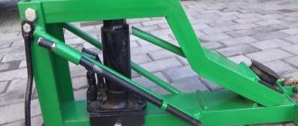
We remake the device with our own hands
Converting a welding machine from alternating to permanent is not as difficult as it might seem at first glance. You don't even have to buy a separate DC welding machine. You can independently assemble the so-called “attachment” for your existing AC welding transformer. The set-top box is connected to a transformer and converts alternating current into direct current.
Below is a simple diagram of such a console.
This attachment essentially plays the role of a mini-rectifier. Assembled using diodes (VD1-VD4). There is a throttle (L1). Thanks to it, the arc is ignited much easier and burns more stable. The set-top box is not built into the transformer, but is a free-standing device. As mentioned above, it connects directly to the AC transformer.
A little about the details. We recommend choosing V200, D161-320 or D161-250 as diodes. They are attached to radiators. The choke is assembled on a core from a TS-270 type transformer. It can be bought secondhand or removed from a tube TV. All windings must be removed and new ones wound. We recommend 20-30 turns. Use copper wires. The optimal cross-section is 16-22 mm2. Between the halves of the core you need to put spacers made of PCB. Their optimal thickness is 0.3-0.5 mm.