Tool selection
A soldering iron is a tool with a heating element used to join fusible materials. According to the method of heating they are divided into:
- electrical;
- hot air;
- gas;
- induction
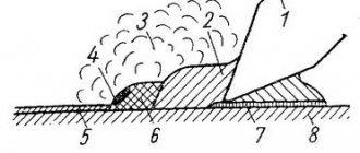
Soldering irons: 1-Electric, 2-Hot air, 3-Gas, 4-Induction
Electric soldering irons are used to work with electrical circuits and SMD boards . On average, they have a power of 15-40 watts. Using devices with a power of more than 100 W, large parts are soldered: radiators, copper tubes of different diameters, etc. Large hammer soldering irons with a power of up to 550 W are used in various industries: mechanical engineering, metallurgy, etc.
The choice of a particular tool is influenced not only by the size of the parts, but also by the thermal conductivity of the material from which it is made. It is this that determines the heating temperature, and, consequently, the required power. For example, copper may require a higher heating temperature than a similarly sized steel part. It is worth noting that when soldering copper parts, a situation may even arise where high thermal conductivity leads to unsoldering of connections made earlier.
The main element of the device (I remind you that we work mainly electrically) is the heating rod. It consists of a copper tube and a nichrome spiral wound on it. On one side of the rod, hidden in the handle of the device, current flows, and on the other, a tip made of a knurled copper rod is inserted. The tip of the sting is sharpened to a bevel. The tip is heated by closing the current on the nichrome spiral.
For electrical work, a lightweight, compact size tool with low heat capacity is suitable. To avoid voltage dissipation, it is better to choose a model that has a three-way ground plug. For a novice electrical engineer, a model up to 30 W will be sufficient. If you plan to repair a car using a soldering iron, then it is better to use 40-watt devices - for quickly connecting wires of any type over a large area. For comfortable operation of soldering irons in cars, special attachments are sold.
Many electronics repairmen use a soldering station. This design includes a set of all the tools necessary for soldering work: a soldering iron with replaceable tips, a stand, a voltage control unit, a hot air gun, cleaners and a desoldering pump.
Many people are interested in the question of whether it is possible to solder without a soldering iron. Yes, you can, in this case the solder and parts will have to be heated for tinning and soldering over an open fire. This allows you to create more or less high-quality connections, but the technology is less secure. In addition, a beginner who does not have sufficient experience may have great difficulties when working with materials such as copper, aluminum or stainless steel.
Features of dismantling
There are many known technical techniques that allow you to solder a microcircuit with a soldering iron, each of which has its own advantages and disadvantages.
You can remove electronic parts from boards without damaging the contacts in the following ways:
- by heating the soldering areas with just a soldering iron (with the addition of flux);
- through a special suction that removes molten solder from the contact pads;
- using a metal braid from a coaxial cable applied to the soldered leg;
- using heat-conducting metal plates (blades) or copper attachments that have slots for the contact patches of microcircuits.
The first three methods are suitable if you have a soldering iron whose power exceeds 25 watts.
The option of using special attachments involves replacing the working tip and is only suitable in combination with “powerful” soldering stations (more than 40 watts), capable of heating it together with the contacts soldered into the board.
In addition, this method of desoldering a part is only suitable for microcircuits with a suitable arrangement of legs for the configuration of the nozzle. The approach that has become more widespread is when a regular razor blade is used as a heater.
Solders and fluxes
Before soldering wires or electrical circuits, you must select the appropriate solder. Tin-silver and tin-lead solders and rosin are suitable for this work. Solders containing lead provide higher quality soldering, but have the disadvantage that this metal is harmful. Tin is used for soldering parts and materials that require safety for the body, for example, dishes.
The marking of solders indicates the metals included in its composition and their content. So, for example, POS-40 solder contains tin and lead (tin-lead solder). The number 40 indicates 40% tin content. The amount of lead in PIC solders affects the color (becomes darker) and the melting point (increases). For electrical work, POS with a tin content of 30% to 61%, as well as PSR-2 and PSR-2.5, are most often used. In the marking of tin-silver PSr-2.5, the number indicates that 2.5±0.3% of the solder is silver.
Solder
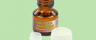
To clean the surface for soldering from oxides, special mixtures are used - fluxes. They are one of the most important factors affecting the quality of soldering. The flux must be selected to match the properties of the material being soldered and be strong enough to destroy the oxide film. Active acid-based fluxes are prohibited from being used for soldering microcircuits and circuit boards, as they cause corrosion and destroy contacts, but when working with chemically resistant metals, you cannot do without them. Today, when soldering, as a rule, they use soldering acid (zinc chloride), alcohol-rosin solution LTI-120 and borax (for soldering metals such as copper, cast iron, steel, brass).
If you are going to solder headphones, speakers or motherboard contacts, then you can use rosin as a flux. However, it should not be used for soldering microcircuit elements and circuit boards. And pay special attention to the following: you cannot use rosin for musical instruments! It heavily contaminates the adhesion site.
Flux
We recommend watching this video. It may answer remaining questions about fluxes and solders.
How to solder correctly with a soldering iron and rosin
Rosin has such unique qualities as ease of dissolution in various organic compounds, for example, acetone or alcohol. When heated, this substance can break down complex chemical compounds such as copper, tin or lead. Therefore, proper use of rosin helps reduce the likelihood of spreading of the substance, destruction of the oxide coating, as well as high-quality tinning of soldered elements.
You also need to take into account that the thinner the tip of the soldering iron, the easier it will be to work with it, especially when it comes to soldering very thin wires and parts. Therefore, if it has not yet been sharpened, this should be done before starting work.
Process description
- First, you should prepare the workspace where you plan to seal the parts. To do this, you need to open the window, since the fumes that come from the solder heavily pollute the air. You should also take any sponge, soak it thoroughly in water and place it as close to the soldering iron as possible. Well, in order not to stain your work area with drops of solder, it is best to cover the surface on which you will be working with thick cardboard or some other similar covering.
- There must be a stand for the device at hand.
- Then you need to plug the soldering iron into a power outlet and heat it up. As the device heats up, a specific smell and noticeable smoke may appear - this is normal. The device will be ready for use immediately after the tip is completely heated and the smoke and unpleasant aroma have evaporated.
- After the tool has been calcined, it should be turned off. This is necessary in order to pre-clean the tip from dirt and plaque. It is best to clean the instrument while it is hot. To do this, you can use a prepared sponge or cloth.
- Then you need to turn on the soldering iron again and let it warm up thoroughly.
- After cleaning and heating the tool, you should carry out the process of tinning the tip of the soldering iron - covering the tip with a light layer of solder, in this case rosin. Thanks to this simple manipulation, the heat transfer between the parts that are intended for soldering will significantly increase.
- Next, you need to dip the tip of the heated device into rosin for a while so that a little solder accumulates on the tip. You should wait a little while until the solder heats up and begins to soften.
- Excess rosin can be removed using cardboard or other available tools.
- If you plan to solder one copper part, then one tinning will be enough - you need to touch the rosin once, then apply the tip of the soldering iron with solder to the working surface and wait a little until the wires are covered with solder. As a result of these manipulations, the rosin will begin to smoke, and the soldered parts will flow around the molten substance.
- In order to solder two parts efficiently, they also need to be tinned separately, that is, covered with solder. It should be remembered that the tinning process is a mandatory procedure, without which it will not be possible to properly solder the necessary parts.
- After finishing work with the soldering iron, while it is still warm, you need to remove the remaining solder. To do this, the tip of the tool just needs to be wiped with a damp cloth, or better yet, a sponge soaked in alcohol or any other composition intended for these purposes.
There should not be any particular difficulties when working with the tool. For everything to go smoothly, it is best to first practice working with rosin on parts that you won’t mind throwing away later. After all, experience always comes with practice.
Preparing for work
Of course, in order to become a master and solder parts of any complexity, you need time and experience. However, in order to repair headphones, attach an LED strip, or change capacitors on a computer board at home, you do not need to have special knowledge. Compliance with the instructions and electrical safety rules will allow you to complete this work without difficulty.
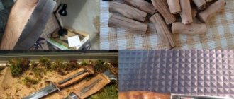
The condition of the tip is of great importance for the quality and efficiency of soldering. The process of caring for it is called tinning - the process of covering its surface with a thin layer of solder. This is done so that the copper from which the soldering iron tip is made does not oxidize. A soldering iron with an oxidized tip interacts poorly with solder and the material being processed. Each time, before soldering with a soldering iron, you should prepare it. First, we treat the tip of a cold soldering iron with a file or a stiff brush, cleaning the copper from dirt.
Cleaning the soldering iron with a brush (you can also use a file)
After cleaning the soldering iron.
Then, after heating the soldering iron to operating temperature, you need to alternately touch the rosin and then the solder several times. The alloy should evenly cover the working part.
Dip the soldering iron into the flux.
We touch the solder tip.
Below is a video on how to tin a soldering iron and prepare it for use. Perhaps the video shows it even better than our photographs, so we recommend watching it.
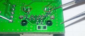
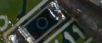
What are the dangers of microcracks in soldering in working devices?
The most dangerous thing about microcracks is sparking and air breakdown in working electronics. All this is accompanied by flammable sparks, loud bangs, acrid smoke, heating and melting of plastic. This is dangerous for humans.
For an electronic circuit, this is dangerous due to the failure of power transistors, expensive processors and burnout of board tracks. In general, this is not very pleasant and leads to expensive repairs. The photo shows soldering defects in the SMD component (resistor) and inhomogeneities in the BGA balls.
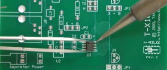
Soldering boards and microcircuits
Very often, electric soldering irons are used for soldering printed circuit boards. A special small device of medium power is suitable for this. We recommend reading the article on choosing soldering irons for boards and microcircuits in more detail.
- First you need to prepare the surface so that it provides minimal resistance and a strong connection.
To degrease the board, you can wipe it with a cloth soaked in a soap solution. To remove hard deposits, a special product sold in a specialized store is suitable. The working area must be cleaned until the copper begins to shine. To treat contacts, you can use regular acetone. A less odorous and dangerous solvent is methyl hydrate. Degrease the board before soldering. - Once you've finished cleaning, place the pins and wires on the diagram. First of all, flat radio components, such as varistors and resistors, are soldered, and after them - large elements: potentiometers, capacitors, transistors, microphones, transformers, etc. This sequence serves to maintain the operating condition of sensitive components. When soldering charges or resistors, the wires should be bent at an angle of 45˚. Short wires and parts such as headphones, speakers, speakers can be pre-secured with insulating tape.
- Apply a small amount of solder to the tip of the heated soldering iron - this will improve the conductivity of the copper. Now you need to heat the connection - press the tip against the board component and hold in this position for 2-3 seconds. Be careful - if the heated area begins to bubble, you should immediately stop heating so as not to damage the board.
Soldering the board. - After applying solder to the soldering iron tip, apply it to the joint in the area being processed. After a small bump appears, you must stop soldering.
- Now you can turn off the soldering iron and start cleaning the area to be treated. In this case, care must be taken - the connection cannot be moved so that it is secured.
Below is a video that clearly describes the whole process: This soldering method allows a beginner to easily solder a radiator to the circuit, solder a button to a modem, an LED strip (more on this below) or repair a plug.
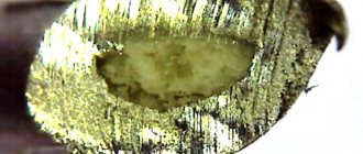
Use of medical needles
In the absence of a special suction device, a novice master can use a medical needle to remove the microcircuit. It must be thin enough to fit into the hole being vacated. At the same time, the needle must have a thickness that allows it to be put on the soldered leg.
Before starting operations, you need to file the tip so that the oblique cut turns out straight, and then flare it a little.
Soldering the part with the resulting device is not difficult at all. To do this, you first need to put the needle all the way onto the pin of the microcircuit, and then use a soldering iron to heat it together with the contact.
While the solder is in the liquid phase, slightly turning the needle, you should push it into the mounting hole (it is advisable to continue rotating until the melt sets).
Upon completion of this procedure, the end of the needle along with the leg will be isolated from the board. Do the same with the remaining legs, after which the microcircuit is unsoldered and removed without any difficulty.
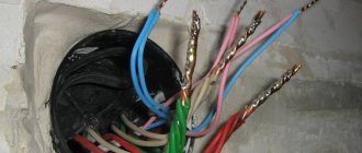
Soldering wires
The ability to solder wires can be useful in many situations. One of the most suitable examples is headphones that came out due to a broken wire. There are two main methods used to connect wires:
- The cores are placed on top of each other and soldered using solder.
- The wire strands are pre-twisted together and then tinned using solder.
In both cases, rosin is used. If it is necessary to clean the wires, liquid flux is applied with a brush. Other methods of soldering wires together are based on the two main ones described above and are presented in the following figure.
Methods for soldering wires together
To solder radioelements without printed wiring, two methods are used. The first (lap) is faster, and the second (twisting) provides greater reliability of the connection.
In order to repair headphones, the second indicated method is best suited (as it will provide greater connection strength). The procedure is approximately as follows:
- Find the damaged section of the wire and cut it out. Strip the edges of the wires to a sufficient length. To remove insulation, it is best to use a heated soldering iron or a flat, not very sharp knife.
- Place the wires next to each other (by color) and tin with rosin or FS-1 mixture.
- Wrap the treated area with electrical tape.
If the wire is damaged at the plug or headphone input, you will need to disassemble the case and solder the wires directly to the input pins.
Work order
Before starting work, it is necessary to prepare all tools, materials and devices so that they are at hand.
When installing or dismantling, the board can be placed on a thermal table. If a soldering gun is used for dismantling, then to prevent its impact on other components, you need to isolate them. This can be done by installing plates made of refractory material, for example, strips cut from old circuit boards that have become unusable.
When using a desoldering pump for dismantling, the process is more accurate, but takes longer. The desoldering pump “charges” as it cleans each leg. As it fills with pieces of solidified solder, it needs to be cleaned.
There are several soldering rules that must be followed:
- Soldering the microcircuits on the board must be done quickly so as not to overheat the sensitive part;
- You can hold each leg with tweezers during soldering to provide additional heat removal from the body;
- When installing using a hair dryer or infrared soldering iron, you must monitor the temperature of the part so that it does not rise above 240-280 °C.
Electronic parts are very sensitive to static electricity. Therefore, when assembling, it is better to use an antistatic mat that is placed under the board.
Soldering LED strip
Today, LED strips are actively used for installing interior lighting of varying complexity. It provides wide design possibilities, is small in size and is not inferior in performance to other lighting devices.
LED Strip Light
Regardless of the size and installation conditions, the tape is soldered according to the same instructions:
- Having cut the tape to the required length, the surface on which it is to be attached is degreased and dried.
- After tearing off the protective film from the back side, the tape is glued to the mounting surface.
- After this, the wires on the input contacts, small parts, dimmers, and controllers are soldered. During operation, you must avoid overheating the tape, this can lead to failure of the diodes.
Pay attention when soldering two strips! Plus should go to plus, and minus to minus!
The soldering process is shown in the photographs below:
We fix the LED strip (electrical tape was used)
A little solder on each contact.
Solder the wires, observing polarity.
Soldering irons with a power of up to 40 W are well suited for soldering diode strips. It is best to use wires with a cross section of 0.75 mm. Red ones are soldered to the positive contact, and black ones to the negative one.
Roll of LED strip.
Now let's talk about how to solder LEDs directly onto the board to create LED backlighting with your own hands. To do this, you will need the diodes themselves, a piece of the board for them (you can buy them at a radio store) and soldering accessories. To remove scale, we will use aluminum flux and tin as solder.
- We insert the diodes into the board so that the positive contacts (long “legs”) are located on one side, and the negative ones on the other. And bend the contacts to the sides. Be careful - if even one diode is connected incorrectly, everything will burn out.
- After treating the “legs” with flux, we solder them to the board.
- Cut off the excess length of the contacts using wire cutters. We strip the power wires to a length equal to the length of the diode row, apply them to the corresponding contacts and solder them.
- Ready! Now you can check the operation of the circuit by connecting the wires to a 12 V power source.
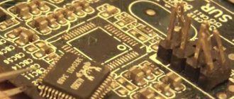
Chip types
The wide variety of microcircuit packages has led to the fact that soldering techniques began to differ. Previously, the most widespread were microcircuits with pin pins for mounting into holes on a printed circuit board. Subsequently, with an increase in the degree of integration and the widespread use of automated soldering lines, surface mount elements with flat or ball leads began to be used.
ICs (integrated circuits) with solder pins are typically DIP and SIP packages with two and one row of pins, respectively.
Surface mounting ( SMD ) allows installation of ICs with pins of the following types:
- Flat leads brought outside the housing - SOIC, SOP, QFP (square housing);
- Flat legs, bent inward, under the body - SOJ, PLCC, QFJ;
- Ball terminals - BGA.
Each variety has several subspecies. The total number of housing types is in the dozens.
DIP housing
Soldering aluminum
There seems to be no difficulty in how to solder aluminum. After all, this material has high thermal conductivity and is easy to process. Despite this, when processing this metal, it is necessary to take into account some features.
Aluminum, when exposed to high temperatures, very quickly forms oxide films on the surface, and therefore for its soldering it is necessary to use special fluxes and soldering tips (coated with steel). And if processing aluminum wires is practically no different from working with other metals, then soldering flat aluminum surfaces is a much more complex process. First of all, you will need a soldering iron with a power of 60-100 W in order to heat large parts well.
- Before soldering aluminum, its working surface is cleaned of scale with sandpaper or a file.
- Afterwards it is degreased with gasoline, acetone or another solvent. Then the joint must be lubricated with a special flux.
- The soldering iron tip is dipped into rosin or ammonia until a slight haze appears. This cleans the copper from which the tip is made from oxides of other metals.
- Further actions are practically no different from working with other materials: the tip is lubricated in solder, after which a small amount of it is transferred to the soldering site for tinning. After this, the main layer of solder is applied.
Stainless steel is soldered in a similar way - this process also requires careful cleaning of the working surface before applying solder.
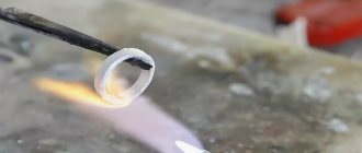
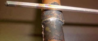
Using a razor blade
To keep the solderings from cooling down, they need to be heated at the same time. To do this you will need an extra plate. An ordinary razor blade will do an excellent job of this task. So all the solders will begin to warm up together after the blade is under a number of these elements.
The main thing is that when heating the power of the soldering iron is enough for a whole row. As soon as the circuit starts to warm up, it definitely needs to be rocked a little. Next, using a knife, carefully remove the blade and the microcircuit itself.
Types of soldering irons
Soldering irons come with a ceramic or spiral heater. The difference is that ceramics heats up much faster, but requires more careful use: a strong blow will cause such a soldering iron to fail.
Spiral is not afraid of impacts, and it will last for many years. When choosing a soldering iron, you need to pay attention to its power. It is necessary to take into account that if you are soldering microcircuits, then it is advisable to choose a soldering iron with a nominal value of 10-20. Soldering irons rated above 60 W are designed for soldering thick wires.
A soldering iron with low power simply will not be able to melt the solder, since the power will be dissipated over a large soldering area. For soldering large metal parts, there are soldering irons from 100 watts and above. The most optimal soldering iron for a beginner is 25-40 W. This soldering iron is considered universal, and it can perform most tasks. Typically, radio amateurs have several soldering irons in their arsenal to cover a wide range of jobs.
Table of models of soldering irons for microcircuits.
In general sale, normal and reliable soldering irons for microcircuits are almost a rarity. If a person is engaged in repairing equipment professionally, he can purchase a suitable working tool. But he would rather choose a soldering station with all the necessary devices for soldering and the ability to set operating modes.
This is interesting! All about semiconductor diodes.