Purpose of the machine
The series of machines has various modifications, but many characteristics within the model range remain the same. 6M12P is an improved version of the N series.
High precision and rigidity are the main advantages of the equipment.
Thanks to the use of such devices, you can perform a large number of operations:
- Milling of various parts based on materials such as non-ferrous and ferrous metals, cast iron and steel. The shape can be any - radius and end, cylindrical, end.
- Support for automatic and semi-automatic cycles. Thanks to this, the machines become indispensable assistants when performing work with an operational nature, with fully automated lines.
- The machines allow you to process horizontal and vertical surfaces, grooves and corners.
- Milling can be counter or down milling.
- High-speed milling is a processing method that makes equipment especially efficient.
6S12 vertical cantilever milling machine. Purpose, scope
The 6S12 milling machine is designed for milling all kinds of parts made of steel, cast iron and non-ferrous metals with face, cylindrical, end, radius cutters in individual and mass production. In mass production, thanks to the presence of semi-automatic and automatic cycles, the machines can be successfully used for operational work in production and automatic lines.
Vertical cantilever milling machines models 6С12 are electrified machines with high precision and rigidity.
The machines can process vertical and horizontal planes, grooves, corners, cut gears, etc.
Milling of gears, reamers, spirals, cam contours and other parts that require periodic or continuous rotation around their axis is carried out on these machines using a dividing head or an overhead round table.
Thanks to the presence of a backlash sampling mechanism in the screw pair of the longitudinal feed of the table, the machine can perform up and down milling, both in simple modes and in modes with automatic cycles.
The most efficient use of the machine is achieved when processing parts using high-speed milling.
The use of the machine in an automatic cycle when processing various stepped parts, milling internal and external frames, etc. in small and large-scale production allows solving problems of increasing its efficiency.
The operation of the SF15 (6S12) machine ensures high milling accuracy. This is achieved by introducing a deceleration unit into the feed drive, which minimizes the inertial overtravel of the table and ensures high dimensional stability when repeating cycles. The machine automatically removes the part from the tool during accelerated movements of the table and returns it to its original position when switching to the working feed, which protects the machined surface from damage by the tool and reduces machine time.
The hydraulic mechanism for selecting backlash in the screw-nut pair helps maintain constant tension regardless of the degree of wear of the nut. Thanks to this, the progressive method of down milling can be widely used on the machine. The presence of a rotating spindle head on the machine and the ability to move the spindle in the axial direction allow milling at various angles.
Using the buttons, you can simultaneously move the table in 2-3 directions, as well as jog mode (the table moves only when the button is pressed).
Depending on your needs, the following control options are possible:
- Handle control
- Push-button control
- Semi-automatic control (pendulum and jump cycles)
The 6S12 machine can be equipped with a rotary table, dividing head and a number of other devices that expand the technological capabilities of the machines.
Machine accuracy class N.
All milling machines in the illustrated catalog
Cantilever milling machines. General information
Horizontal and vertical cantilever milling machines are the most common type of machines used for milling work.
Cantilever milling machines get their name from the cantilever bracket (console), which moves along the vertical guides of the machine bed and serves as a support for the horizontal movements of the table. The standard sizes of cantilever milling machines are usually characterized by the size of the working (mounting) surface of the table. Cantilever milling machines can have a horizontal , universal (widely universal) and vertical design with the same size of the working surface of the table. The combination of different versions of the machine with the same basic dimensional characteristics of the table is called the dimensional range of machines .
In the USSR, the production of cantilever milling machines of five standard sizes was mastered: No. 0; No. 1; No. 2; No. 3 and No. 4 , and a full range of machines was produced for each size - horizontal, universal and vertical. Each machine of the same size range had the same designation in the code, corresponding to the size of the working surface of the table.
Depending on the size of the working surface of the table, the following sizes of cantilever milling machines are distinguished:
| Size | Range of machines | Table size, mm |
| 0 | 6Р10, 6Р80, 6Р80Г, 6Р80Ш | 200 x 800 |
| 1 | 6N11, 6N81, 6N81G; 6Р11, 6Р81, 6Р81Г, 6Р81Ш | 250 x 1000 |
| 2 | 6S12, 6M82, 6M82G; 6Р12, 6Р82, 6Р82Ш; 6T12, 6T82, 6T82G, 6T82Sh | 320 x 1250 |
| 3 | 6M13P, 6M83, 6M83G; 6Р13, 6Р83; 6T13, 6T83, 6T83G | 400 x 1600 |
| 4 | 6M14P, 6M84, 6M84G | 500 x 2000 |
In accordance with the size of the table, the overall dimensions of the machine itself and its main components (bed, table, slide, console, trunk), the power of the electric motor and the magnitude of the greatest movement (stroke) of the table in the longitudinal direction, the slide in the transverse direction and the console in the vertical direction change.
Russian and foreign analogues of the 6S12 machine
FSS315, FSS350MR, (FSS450MR) - 315 x 1250 (400 x 1250) - manufacturer Gomel Machine Tool Plant
VM127M - (400 x 1600) - manufacturer Votkinsk Machine-Building Plant GPO, Federal State Unitary Enterprise
6D12, 6K12 - 320 x 1250 - manufacturer Dmitrov milling machine plant DZFS
X5032, X5040 - 320 x 1320 - manufacturer Shandong Weida Heavy Industries, China
FV321M, (FV401) - 320 x 1350 (400 x 1600) - manufacturer Arsenal JSCo. — Kazanlak, Arsenal AD, Bulgaria
Location of controls
In total, the device has about 34 parts that are involved in the processes of adjustment and control of the equipment. These are various handles, taps, buttons, switches. You can't do without using a clamping nut. All parts are fixed to the main body; if necessary, they can be easily accessed.
To read: Self-production of a CNC machine
Information about the manufacturer of the 6S12 cantilever milling machine
The 6S12 vertical cantilever milling machine was produced by the Lugansk Machine Tool Plant .
Lugansk Machine Tool Plant was one of the first in the former Soviet Union to master large-scale production of milling machines with cyclic and numerical program control systems. The plant developed and put into production particularly complex high-performance machines with automatic tool change and numerical control of models SVM1F4 and SF68F3P. The plant has mastered the production of small-sized lathes MS-03 and MS-04, milling machines MS-51, MS-54, SVF1 and drilling machines SVS1-010.
Machine tools produced by Lugansk Machine Tool Plant
- 6A12P
- vertical cantilever milling machine with program control 320 x 1250 - 6S12
- vertical cantilever milling machine 320 x 1250 - MS-03
- small-sized screw-cutting lathe Ø 270 - MS-51
- desktop vertical milling machine 200 x 500 - SVM1F4
- vertical milling machine with CNC and ASI - SVF-1
- vertical tabletop milling machine 320 x 100 - SF-15
- vertical cantilever milling machine 320 x 1250 - SF-35
- vertical cantilever milling machine 320 x 1250 - SF-40
- vertical cantilever milling machine 320 x 1250
List of components
The machines are equipped with special mechanical parts, due to which, among other things, the work is organized:
- Safety equipment responsible for separate activation. A coupling is added to it, protecting the part with the engine from additional overloads.
- Spindle braking system.
- Automatic intermittent feeding mode.
- Feed stops. Participate in turning units on and off.
- Feed blocking. Manual or mechanical.
Technical characteristics of the cantilever milling machine 6S12
| Parameter name | 6S12 | 6Р12 | 6T12 |
| Basic machine parameters | |||
| Table surface dimensions, mm | 1250 x 320 | 1250 x 320 | 1250 x 320 |
| Maximum mass of the workpiece, kg | 250 | 400 | |
| Distance from the end of the spindle to the table, mm | 460 | 30..450 | 30..450 |
| Distance from the spindle axis to the vertical guides of the bed (overhang), mm | 400 | 350 | 380 |
| Desktop | |||
| Maximum longitudinal stroke of the table (X), mm | 950 | 800 | 800 |
| Maximum transverse travel of the table (Y), mm | 300 | 250 | 320 |
| Maximum vertical travel of the table (Z), mm | 410 | 420 | 420 |
| Movement of the table by one division of the dial, longitudinal (X), transverse (Y), mm | 0,05 | 0,05 | 0,05 |
| Movement of the table by one division of the vertical dial (Z), mm | 0,01 | 0,01 | 0,01 |
| Limits of longitudinal and transverse table feeds (X, Y), mm/min | 20..2500 | 12,5..1600 | 12,5..1600 |
| Limits of vertical table feeds (Z), mm/min | 8..400 | 4,1..530 | 4,1..530 |
| Number of feeds longitudinal/transverse/vertical | 18 | 22 | 22 |
| Speed of rapid movements longitudinal (X), transverse (Y), m/min | 2,5 | 4 | 4 |
| Speed of rapid vertical movements (Z), m/min | 1 | 1,330 | 1,330 |
| Force allowed by the feed mechanism for longitudinal feed (X), kg | 1400 | ||
| Force allowed by the feed mechanism for cross feed (Y), kg | 410 | ||
| Force allowed by the feed mechanism for vertical feed (Z), kg | 740 | ||
| Spindle | |||
| Spindle speed, rpm | 31,5..1600 | 40..2000 | 31,5..1600 |
| Number of spindle speeds | 18 | 18 | 18 |
| Spindle quill movement, mm | 80 | 70 | 70 |
| Milling spindle taper | 50 GOST 15945-70 | No. 3 GOST 836-62 | |
| Spindle end | 50 | ||
| Rotate the spindle head right and left, degrees | ±45 | ±45 | ±45 |
| Machine mechanics | |||
| Feed stops (longitudinal, transverse, vertical) | Eat | Eat | Eat |
| Blocking manual and mechanical feeds (longitudinal, transverse, vertical) | Eat | Eat | Eat |
| Blocking separate feed switching | Eat | Eat | Eat |
| Spindle braking | Eat | Eat | Eat |
| Overload safety clutch | Eat | Eat | Eat |
| Automatic intermittent feed | Eat | Eat | Eat |
| Electrical equipment, drive | |||
| Number of electric motors on the machine | 4 | 3 | 4 |
| Main motion drive electric motor, kW | 5,5 | 7,5 | 7,5 |
| Feed drive electric motor, kW | 1,5 | 2,2 | 3 |
| Electric motor of the backlash selection mechanism pump, kW | 0,08 | — | — |
| Tool clamping motor, kW | — | — | 0,25 |
| Coolant pump electric motor, kW | 0,125 | 0,12 | 0,12 |
| Total power of all electric motors, kW | 9,825 | 10,87 | |
| Dimensions and weight of the machine | |||
| Machine dimensions (length width height), mm | 2000 x 2230 x 2030 | 2305 x 1950 x 2020 | 2280 x 1965 x 2265 |
| Machine weight, kg | 3000 | 3120 | 3250 |
- Vertical milling machines models 6S12 and SF-15. Manual. Lugansk Machine Tool Plant named after. Lenin, 1970
- Avrutin S.V. Fundamentals of Milling, 1962
- Avrutin S.V. Milling, 1963
- Acherkan N.S. Metal-cutting machines, Volume 1, 1965
- Barbashov F.A. Milling business 1973, p.141
- Barbashov F.A. Milling work (Vocational education), 1986
- Blumberg V.A. Milling machine handbook, 1984
- Grigoriev S.P. Practice of coordinate boring and milling work, 1980
- Kopylov R.B. Working on milling machines, 1971
- Kosovsky V.L. Handbook of a young milling operator, 1992, p. 180
- Kuvshinsky V.V. Milling, 1977
- Nichkov A.G. Milling machines (Machinist's Library), 1977
- Pikus M.Yu. A mechanic's guide to repairing metal-cutting machines, 1987
- Plotitsyn V.G. Calculations of settings and adjustments of milling machines, 1969
- Plotitsyn V.G. Setting up milling machines, 1975
- Ryabov S.A. Modern milling machines and their equipment, 2006
- Skhirtladze A.G., Novikov V.Yu. Technological equipment for machine-building industries, 1980
- Tepinkichiev V.K. Metal cutting machines, 1973
- Chernov N.N. Metal cutting machines, 1988
- Frenkel S.Sh. Handbook of a young milling operator (3rd ed.) (Vocational education), 1978
Bibliography:
Related Links. Additional Information
- Milling machines: general information, classification, designation
- Comparative characteristics of cantilever milling machines of the 6N, 6M, 6R, 6T
- Feed box for console milling machines of the 6M : 6M12P, 6M13P, 6M82, 6M83, 6M82Sh, 6M83Sh
- Feed box for console-milling machines of the 6P : 6Р12, 6Р13, 6Р82, 6Р83, 6Р82Ш, 6Р83Ш Feed box for console-milling machines of the 6Т : 6T12, 6T13, 6T82, 6T83, 6Т82Ш, 6Т83Ш
Electrical equipment of milling machines of the Gorky Machine Tool Plant, GZFS
Electrical equipment of milling machines of the Vilnius Zalgiris Machine Tool Plant
Additional technical characteristics, analogues
The device has the following analogues, corresponding to the source code in terms of kinematics and technical characteristics:
- Models from the Chinese enterprise Shandong Weida with number X5040 and X
- The Belarusian plant from Gomel produces FSS350VR products.
- The Dmitrov Russian plant offers versions of the 6K12 and 6D12 machines.
- Bulgarian designs FV321M.
On the basis of the machine described above, other types of equipment were created. The combinations are almost no different from each other.
- 6R13RFZ. It is equipped with a turret head and is controlled by a numerical software complex.
- 6B12, 6M12, 6R12.
- 6M12P. A unit with increased precision, production started in 1961.
- 6E12 and 6E12-1. Distinctive features include increased speed and feed speed, and a large number of revolutions.
- 6M12PB.
Modern models
Modern industrial enterprises widely use high-precision numerical control equipment, however, it is impossible to imagine an enterprise without mechanically controlled equipment. Although it can be called mechanical only conditionally, since almost all structural elements are powered by electric drives. The table and spindle feed drives remained mechanical, with duplication of setting a constant numerical feed value by an electric drive.
Manufacturers of vertical milling machines produce models that have equally recognizable features.
The main disadvantage of all models can be considered high cost and limited service life. In addition, it is difficult to find a specialist who can repair the problem if the supplier does not provide follow-up service after selling the product.
Vertical milling machines include the following models: 6М12П, 6Р12Б, 6С12, 6Н12, 6Р12, 6Т12. They have found wide application not only in the former republics of the USSR, but are also successfully exported abroad. This is reliable, high-quality equipment that does not require close attention. Modern factories systematically improve the design of equipment and, if possible, increase the cutting speed. From year to year, the technological capabilities of various models are improving.
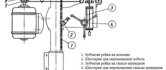
About the frame and console
Machines of any type are equipped with a basic unit in the form of a bed. The remaining working units and mechanisms are mounted on this surface. The bed is characterized by the following parameters:
- A large number of ribs.
- Trapezoidal section, developed.
- Highly reliable base.
The gearboxes are standard inside the frames. The turning head is inside the front parts. Installation is carried out using guides shaped like a circle. The console is placed on guides vertically. Characteristic is the separation of the main unit and the base. A bolted connection will allow you to secure the two components to each other.
When approaching from the right, access to the gearbox and pump is easy. To do this, use a window, usually closed with a special lining. The pump is used to supply lubricant to other internal parts. The speed controller opens on the left side. The base of the machines also has a special container where the cooling compound is placed. At the back of the base there is a hole through which liquid is drained if necessary.
Among the basic units is the console part of the machine. Thanks to this part, the transmission chain of various equipment is connected into one whole. It also participates in the distribution of movement into gears of various types. The feed motor is located at the bottom of the system. The movement through the gearbox goes to the cantilever gears.
To read: Algorithm for making a sawmill yourself
Recommendations for use
Electrical diagram of the machine
Before starting work on the machine, it is necessary to study the equipment passport and its characteristics. It presents technical requirements for installation, operating rules and procedures for carrying out repair and maintenance work.
The choice of equipment installation location is determined according to its dimensions, weight and characteristics. In this case, it is necessary to take into account the free space for the worker, as well as the installation of the workpiece on the work table. In the latter case, special lifting mechanisms are often used.
Additionally, the passport contains the following recommendations for the operation of the 6P12 vertical milling machine:
- After unpacking, it is necessary to remove the protective and lubricating layer from the surface of the machine. For this purpose, special compounds are used;
- performing the procedure for lubrication of units and components according to the diagram in the passport;
- Before starting work, the absence of defects and the correct configuration of the equipment are checked. It is taken into account that its actual performance indicators may differ from the nominal ones due to long-term operation;
- After installing the cutter, it is necessary to install a protective fence. It is included as standard equipment;
- Upon completion of installation, the machine starts at idle speed without installing the workpiece. All operating modes are checked.
A short video review will give you an impression of the capabilities of the 6P12 machine:
List of controls
The following components of the machine are no less important than the previous ones:
Gearbox or gearbox
The equipment has a total of 18 gear indicators. This is a separate unit. Usually located on the console, on the left side. The gear shift device is located directly on the console. The front part is equipped with a so-called dial - it is used to apply certain gear indicators to the surface. Marks allow you to easily set feed rates for the working surface, in horizontal or vertical planes.
Swivel head
It looks like a spindle that is positioned vertically. Supplied with an additional roller for receiving. The spindle moves along the axis using a special flywheel, the latter is placed inside a special sleeve. The handle is located inside the left side of the sleeve. This makes it easy to clamp if necessary.
Gearbox
A total of 18 numbers are used on which the spindle rotates. Installed inside the frame body. The shafts of this box are mounted on ball bearings. The plunger pump that regulates lubrication is located on one of these parts.
Sled with work table
The slide is clamped to the console using eccentric clamps. The movement begins from a screw located transversely. At the next stage, everything moves to guides in the shape of a rectangle, console type.
The table also moves using the guides mentioned earlier. He is the final component of the serve chain, which respects the longitudinal position. The rotating screw is responsible for the implementation of such a scheme. The claw clutch handle must be turned on for movement to begin.
The table can be configured in three modes: pendulum, automatic and semi-automatic.
The pendulum mode is controlled using cams. The parts are mounted on the side surface of the table, located in front. If a blockage occurs at the longitudinal stroke lever, the pendulum operating mode cannot be stopped, this leads to damage to the unit.
Setting up a cantilever milling machine model 6M12P
GGTU named after P.O. Sukhoi, MRSiRI, MRS, setting up the 6M12P machine, 2015
Milling an Archimedean spiral on a disc cam. Machine 6M12P, Lift h=75mm, angle 45, Outer diameter of cam D=250mm, Material - steel 45ХН
TECHNICAL CHARACTERISTICS OF THE MACHINE model 6M12P Dimensions of the working platform of the table in mm 320 1250 Limits of the angle of rotation of the table in degrees 45 Number of rotation speeds of the horizontal spindle 18 Limits of spindle revolutions per minute 31.5-1600 Limits of feed rates in mm/min: longitudinal 25-1250 transverse 25-1250 vertical 8.3-416.6 Spindle drive electric motor power in kW 7
The main advantages of the 6M12P machine: 1. fastening of the tool in the spindle - a mechanized process 2. the screw pair is equipped with an additional periodic control system 3. a safety clutch is installed that protects against overloads 4. the spindle rotation range and machine feed modes are quite high 5. reliability, quality of operations performed and an appropriate level of safety 6. The working surface is increased compared to analogues. By installing additional equipment on the 6M12P milling machine (vice, universal head, gearboxes, etc.), the quality of processing can be significantly improved. The technological capabilities of machines can be expanded by using a dividing head on them.
Contents: General view of the 6M12P machine, kinematic diagram, adjustment, software
Software: KOMPAS-3D 15
Kinematic scheme
The main component of the movement of the device is an electric motor with a power of 7.5 kW. Through an elastic coupling, the movement from this device passes to one of the shafts. From the first shaft to the second, energy is transferred through a gear drive.
A block is placed at the second shaft, complemented by gear-shaped wheels. Thanks to this part, the movement moves to the third shaft. The device supports three different transmission speeds. Gear screws are also involved in this process.
The main feedbox operates at 18 speeds. If you turn on the friction clutch, the tool can be quickly moved around the table, regardless of the technical characteristics. In this case, the process is also organized using the main electric motor along with the shaft and gears.
To read: Description and characteristics of a vertical milling machine with CNC 6r13f3
Download the diagram on an enlarged scale
Kinematic diagram
The kinematic diagram shows that the drive is connected to the electric motor through a coupling. It is responsible for transmitting movement to the structural unit. The transformations of the three blocks determine the number of spindle revolutions. Communication up to 13 speeds is possible, without the need to change in stages.
An electric motor located in the console acts as a gear drive. This happens by one of 18 different feeds through the jaw coupling to the screws. Those, in turn, on a horizontal mill can be of three types: vertical, longitudinal and transverse.
The function of the travel friction is important, which carries out movements through the gears before the feeds. This part is connected to the coupling, simultaneous functionality is limited. The frame is fixed with pins according to the scheme, fixed in a rigid way.
Gearbox and spindle
The gearbox is located in the upper part of the frame body. It is controlled using a plug-in switch box. Which, in turn, is mounted on the left side. Gaining access to service parts is easy; simply remove the cover on the right.
A spindle is mounted in the rotating head. Four bolts are used for fastening.
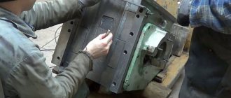
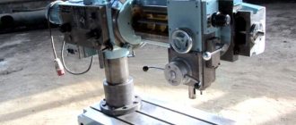
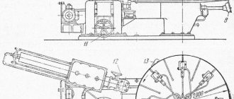
Spindle head of cantilever milling machine 6С12
Spindle head of cantilever milling machine 6С12
List of components of the spindle head of the 6S12 cantilever milling machine
- horizontal shaft bearings
- adjusting screws
- intermediate shaft bearings
- lubricant tube
- washer
- bearings
- screw
- screw
- bracket
- bevel gears
- screw
- screw
- movable nut
- gear
- bearings
- quill
- Radial roller bearing A—3182118
- spindle
- half rings
- angular contact ball bearing SA—36214
- ring
- intermediate shaft
- glasses
- bolt
- glasses
- screw
Description of the machine spindle head
The rotary spindle head is a shaped cast iron casting, in the bores of which the following are mounted:
- movable quill 17
- spindle 19
- intermediate shaft 23 with gear transmission
The front support of the spindle is a double-row radial roller bearing A3182118. The rear support is two angular contact ball bearings CA 36214. The tension of the bearing of the rear spindle support is carried out by grinding the rings 22, and the bearing A3182118 - by grinding the half rings 20.
The spindle is unloaded. Axial and radial loads occurring on gear 14 are absorbed directly by the housing through the bearings.
The mechanism for moving the quill consists of a bracket with a nut 8, rigidly fixed to the quill and a screw 7, which rotates through a conical pair 10 when the flywheel is turned. When moving the quill, you must loosen the clamping screw located on the front side of the spindle head.
The spindle head is rotated using a worm gear mounted in the flange part of the frame.
Installation and dismantling of the machine spindle head
The head is installed with the worm removed. Having inserted the head into the frame at 50% of its fit, turn the spindle 19 to align the splines, then install and secure the head with the cavity.
Screw in the worm and bushing and secure it with a screw and a tapered pin.
Adjusting the meshing of bevel gears
Adjust the engagement of the bevel gears by moving the glasses 24 and 26. To do this, you need to loosen 3 screws 27 and 3 bolts 25. When moving the screws 27, make adjustments.
The lateral clearance between the teeth of the bevel gear should be in the range of 0.17 - 0.24 mm. The length of the contact patch is at least 50% of the length of the tooth, the width is at least 50% of the working height of the tooth.
Bearing adjustment
All angular contact bearings are adjusted by grinding the rings. Bearings 21 of the upper spindle support are installed with preload.
The preload of the lower bearing 18 must be ensured by seating the bearing on the conical journal of the spindle by grinding the half rings 20.
The axial play of the bearings of the intermediate shaft 23 should be in the range of 0.02–0.03 mm.
Adjusting the backlash in the screw-nut pair
To select the backlash in the screw-nut pair, loosen nut 11 and screw 12, then turn the movable nut 13 to eliminate the backlash and lock it.
Feed mechanism
Typically, feed mechanisms consist of several shafts. And each device has its own operating features:
- The 6th shaft is mounted on three ball bearings.
- The clutch of this part is adjusted as it moves. To do this, you need to use screws screwed into the flange.
- The fifth shaft is installed using the same rule. Tightening the nut from the left end is enough to adjust this part.
- The fourth shaft is located on three supports, thereby increasing rigidity.
- The spline type of devices includes shafts 2, 3 and 4. They are involved in the movement of gear blocks.
The gear shift mechanism, in fact, becomes a separate independent unit. On the surface there is dial 1, where all 18 spindle revolutions are applied.
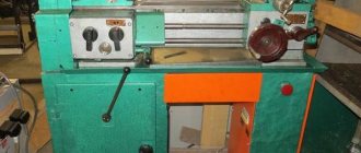
Location of controls for the 6S12 cantilever milling machine
Location of controls for the 6S12 milling machine
List of controls for the 6S12 cantilever milling machine
- Handle for longitudinal movement of the table
- Control panel "Left"
- Gear shift knob
- Quill clamp screw
- Head zero position lock
- Quill moving handle
- Coolant valve
- Block of travel limit switches “Longitudinally”
- Electrical panel
- Limit cams
- Head rotation screw
- Head clamp nut
- Quill extension stop
- Limit cams
- Limit cams
- Limit cams
- Control panel "Right"
- Slide Clamp Handle
- Longitudinal movement dial
- Vertical movement dial
- Transverse movement dial
- Feed shift knob
- Fast Feed Button
- Spindle start button
- "General stop" button
List of components of the 6S12 cantilever milling machine
- Left control panel - SF1.06.00.000
- Spindle head - SF15.02.00.000
- Bed with gearbox - SF2.01.00.000
- Right control panel - SF2.07.03.003
- Speed shift mechanism SF1.23.03.000
- Table-sled - SF2.04.00.000
- Console - SF2.03.00.000
- Feed box - SF2.06.00.000
- Electrical equipment - SF15.12.00.000
- Block of limit switches - SF2.08.00.000
- Mechanism for raising and lowering the console - SF1.21.00.000
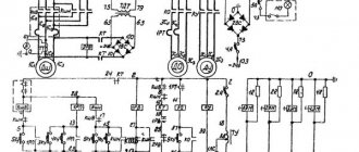
Electric scheme
The electric motor participates in the formation of the main movement. Its power, type and number of revolutions are indicated in the official technical accompanying documents. In addition, the work involves elements such as:
- Friction clutches.
- Size of friction surfaces.
- Number of friction surfaces.
- Surface material.
Download the diagram on an enlarged scale
Description of electrical equipment
A three-phase current network with a voltage of 380 V should become the main power source, all parts are configured for this. In addition, the electrical circuit also assumes other types of power:
- From 127 V voltage networks.
- The local lighting circuit is powered by a voltage of 36 V.
- Use of zero protection for all electric motors.
- Using fuses to protect every part.
- Thermal relays providing additional protection.
Push-button control is carried out from two command devices. A three-position switch allows you to perform the first three modes.