The theodolite device is used when performing construction, geodetic and other work. The theodolite device allows you to accurately determine the value of vertical and horizontal angles (there are such optical and electronic devices).
Diagram of the axes of repeating and simple theodolites: 1 – theodolite stand, 2 – limb, 3 – alidade, JJ – the main axis of the theodolite, UU – level axis, VV – sighting axis, TT – horizontal axis of rotation of the pipe.
In addition to the fact that this device measures horizontal and vertical angles, it is also used to determine distance.
Depending on the accuracy of the device, there is the following classification:
- high-precision equipment is designated T1;
- instruments with normal accuracy are designated T2, T5;
- T15, T30 devices are suitable for technical use;
- educational equipment is marked T60.
Based on the marking of the device, you can find out the root-mean-square error that it will allow when measuring angles.
Description of the theodolite itself
With its help, fairly accurate measurements of horizontal and vertical angular quantities are made.
Externally, it is made in the form of a U-shaped optical device located on a rotating platform. The device platform is made in the shape of a circle, on which angular divisions are marked. In addition to the horizontal one, there is also a vertical circle with the same angular divisions. To measure range, it is equipped with various rangefinders. Modern theodolites have electronic components that improve the accuracy of measurements.
Theodolite and its components
The design of a theodolite is based on the laws of optics, mechanics, and electronics.
Theodolite device 2t30
The theodolite diagram includes the following main parts:
- the optical part of the device is a telescope;
- two perpendicularly located circles (one vertical, the other horizontal);
- Tragger systems (allowing you to remain in a stable state for a long time);
- built-in microscope (measurement method can be line or scale);
- a special rotary ruler (called an alidade);
- fixing and guiding screws;
- adjustable tripod (with its help, installation on the ground and preparation of the device for operation).
Main components of theodolite
Despite the variety of such measuring devices, the structure of the theodolite remains the same:
- sighting tube, which is fixed between two vertical columns;
- reading devices (made in the form of circles with measuring scales marked along the perimeter);
- in mechanical devices, reading devices have a bar or scale system;
- optical plummet (called “pivot”);
- adjusting device (called “cremariere”);
- All of the listed device systems are located on a tripod.
The theodolite cremarier allows you to solve the following range of problems:
- rigidly fix the position of the optical sighting device (this is necessary for accurately taking readings from the dial);
- measure the distance to the selected object;
- make accurate sighting of objects regardless of range;
- adjust the focusing lens;
- bring the main axis of the entire apparatus into a strictly vertical position;
- contributes to obtaining the so-called “virtual image”.
Reading devices
These devices allow you to count the divisions of the device dial up to the permitted fractions. They are divided into three categories: line, scale, micrometers. The angular scale can be located on a circle. In this case, it is called a goniometric circle or limb. Each of them has its own angular value for dividing the limb. In real instruments, the division accuracy varies in the range from one degree to five arcminutes. The size of the dial (diameter) is determined by the design of the theodolite. The size can vary from 72 mm to 270 mm.
The following can be used as a reference index: a single stroke, a double stroke, which is called a bisector, a zero stroke, a stroke of the main scale of the existing dial.
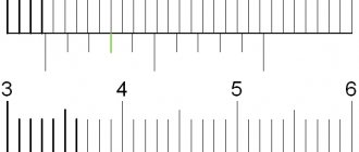
The simplest measuring device is a vernier.
Levels
They are necessary for precise adjustment of the theodolite relative to its vertical guide. They are used to measure small angles in the vertical plane. Any level consists of the following elements:
- a small glass flask containing a special liquid inside;
- housings that protect the flask from mechanical influences.
They are made round or cylindrical.
Flasks of cylindrical levels are made from special glass, which contains molybdenum. The liquid inside the flask is ethyl alcohol. Indelible strokes are applied to its surface at intervals of 2 mm. The minimum angle of inclination in any direction at which bubble displacement is observed is called the maximum sensitivity value.
Circles are drawn on the surface of the glass of cylindrical levels from the center to the edge with the same interval.
2.2.2. Construction of theodolites
The theodolite device is based on the principle of measuring a horizontal angle (Fig. 15).
During geodetic work, it is not the angle between the sides that is measured, but its orthogonal (horizontal) projection, called the horizontal angle. So, to measure angle ABC
(Fig. 15) you must first project points
A
,
B
, and
C
and measure the horizontal angle
abc = β
.
Consider the dihedral angle between vertical planes V1
and
V2
passing through the sides of angle
ABC
.
The angle β
for a given dihedral angle is linear.
Consequently, the angle β
is equal to any other linear angle, the vertex of which is located at any point on the vertical edge
BB1
of the dihedral angle, and its sides lie in a plane parallel to the
plane
M. So, to measure the value of angle β
, you can at any point lying on edge
BB1
of a dihedral angle, say at point
b 1
, install a horizontal circle with degree divisions and measure on it the arc
a 1 c1
enclosed between the sides of the dihedral angle, which will be degree the measure of the angle
a1b1c1
equal to
β
, i.e. angle
abc = β
.
To measure horizontal projections of angles between terrain lines in a theodolite, a horizontal goniometric circle with degree divisions, called a limb
.
The sides of the angle are projected onto the limb using a movable sighting plane of the telescope
.
It is formed by the sighting axis
[1] of the pipe when it rotates around a horizontal axis.
This plane is alternately combined with the sides of the angle BA
and
BC
of
the telescope to points
A
and
C. Using a special reading device alidade
, which is located above the limb coaxially with it and moves along with the sighting plane, the beginning and end of the arc
a 1 c1
(see Fig. 15), taking readings in degree divisions.
The difference between the taken readings is the value of the measured angle β
.
The limb and alidade used to measure horizontal angles form a horizontal circle
17 (Fig. 16).
The axis of rotation of the alidade of the horizontal circle is called the main axis of the theodolite
.
The theodolite also has a vertical circle
18 (Fig. 16) with a limb and an alidade, used for measuring vertical projections of angles - inclination angles. It is customary to consider angles of inclination above the horizon to be positive, and below the horizon to be negative. The vertical circle limb is usually tightly attached to the telescope and rotates with it around the horizontal axis of the theodolite.
Fig. 16. Theodolite T30 structure: 1 – base; 2 – cylindrical level correction screw; 3, 4 – fixing and guiding screws of the alidade; 5 – cylindrical level; 6 – telescope guiding screw; 7 – ratchet; 8 – fixing screw of the telescope; 9 – sight; 10 – telescope eyepiece; 11 – eyepiece of the reference microscope; 12 – column; 13 – stand; 14 – dial fixing screw; 15 – lifting screw; 16 – dial guide screw; 17 – horizontal circle; 18 – vertical circle; 19 – telescope lens; 20 – mirror for illuminating the lines of the reading microscope; 21 – bracket for reference compass;
Before measuring angles, the center of the limb of a horizontal circle, using a plumb line or an optical plummet, is set on a plumb line passing through the vertex of the angle being measured, and the plane of the limb is brought to a horizontal position, using for this purpose three lifting screws 15 and a cylindrical level 5 (Fig. 16). As a result of these actions, the main axis of the theodolite should coincide with a plumb line passing through the vertex of the measured angle.
To install, adjust and point the theodolite at the target, it has a system of screws: mounting and lifting screws, fixing (clamping) and guiding (micrometer) screws, correction (adjusting) screws.
The theodolite is secured to the head of the tripod with a mounting screw, and it is leveled with lifting screws.
Fixing screws secure the moving parts of the theodolite (limbo, alidade, telescope) with the fixed ones. Guiding screws impart small and smooth rotation to the fixed parts.
Theodolite telescopes are most often astronomical, giving a reverse (inverted) image. But recently, tubes have been used that give a direct image.
When observing objects, a very specific point of the pipe is pointed at them. Such a point is the center of the grid of threads, which is the intersection of a horizontal thread and an extended vertical one. The grid of threads (Fig. 17) is visible in the field of view of the tube and is depicted on a special grid diaphragm located near the front focus of the eyepiece. The mesh diaphragm is a glass plate in a metal frame.
It can be slightly moved in horizontal and vertical directions using the mesh adjustment screws. Rangefinder strokes are applied symmetrically relative to the horizontal thread to determine distances.
The optical characteristics of a telescope include: magnification, field of view, relative brightness and resolution, which is taken as the accuracy of sighting by the telescope.
The magnification of the telescope shows how many times the size of an object viewed through the telescope increases compared to the size of the same object visible to the naked eye.
The field of view of a pipe is the space that is visible through the pipe when it is stationary.
The brightness of an image is determined by the amount of light that falls on the eye per second of time per square millimeter of the image. This brightness is called absolute; it cannot be expressed in a specific number. Therefore, they use relative brightness, which is the ratio of the absolute brightness of the eye equipped with a telescope and the naked eye.
To bring the axes and planes of the device into a vertical or horizontal position, levels are used; they come in two types: round - for preliminary, rough installation of devices and cylindrical - for final, precise installation. A cylindrical level is a glass tube, the inner surface of which is polished in the form of a barrel-shaped vessel, in the longitudinal section representing a circular arc of a certain radius.
Glass vessels of levels are filled with ether or a mixture of ether and alcohol in a heated state. When the filler cools and contracts in volume, a space is formed filled with filler vapor, that is, a bubble. When the temperature changes, filler vapors easily pass from a vapor state to a liquid state and vice versa, causing the size of the bubble to change. In cylindrical levels, ensure that the length of the bubble is approximately 1/3 of the length of the tube at a temperature of +20°C. To make it possible to judge the movement of the bubble, strokes are applied to the outer surface of the level. The distance between strokes is usually 2 mm. The middle of the level tube is called the null point. At the cylindrical level, the zero point is usually not indicated, and strokes are applied symmetrically relative to it. The tangent to the inner surface of the tube passing through the zero point along the length of the cylindrical level is called the level axis. When the middle of the level bubble coincides with the zero point, the level axis takes a horizontal position. When the level bubble is shifted by one division, the level axis tilts by a certain angle, which is called the level division value. The lower the level division price, the more sensitive and accurate the level.
Let us consider in detail the structure and characteristics of the T30 theodolite and its modifications (2T30, 4T30P), which are usually used in engineering and geodetic work.
Theodolite T30
(Fig. 16) and its modifications belong to the category of technical ones with a repeating system of the vertical axis. The counting system is one-sided. Pipe magnification 18x (T30) and 20x (2T30, 4T30P), sighting limits from 1.2 m to infinity, cylindrical level division 45″. These theodolites are used for laying theodolite and tacheometric traverses, planning and high-altitude surveys.
The telescope (see Fig. 16) has an optical sight 9, in the field of view of which a light cross is visible. This cross is combined with a target (object) that should fall into the field of view of the pipe, but the image of the object may be blurry (sometimes its image will not be visible at all). In order for the image of an object to be clear, first, by rotating the diopter ring of the eyepiece of the telescope 10, a clear image of the reticle is obtained (this action is called setting the telescope to the eye). Then, using the ratchet 7, a special focusing lens is moved in the pipe until the image of the target becomes clear, i.e., the pipe is positioned over the object. After this, the clamping screws of the telescope 8 and the alidade of the horizontal circle 3 are secured, and the center of the grid of threads is aimed at the object with micrometer screws of the alidade 4 and tube 6.
In the T30 theodolite, the stand 13 is rigidly attached to the base 1, which simultaneously serves as the bottom of the case, which allows you to close the theodolite with the case without removing it from the tripod. The axis of rotation of the theodolite is set to a vertical position using lifting screws 15 and a cylindrical level with the alidade of the horizontal circle 5.
The hollow vertical axis of the theodolite allows the device to be centered over a point in the terrain using a spotting scope. The device is equipped with eyepiece attachments for a telescope and a microscope, which are used when observing objects located at an angle of more than 45° relative to the horizon.
In T30 theodolites there is only one cylindrical level at the alidade of the horizontal circle 5, which is attached to the stand of the telescope parallel to the sighting plane. The position of the level is changed by adjustment (correction) screws 2. With alidade, there is no vertical circle of level.
On special order, the theodolite can be equipped with a reference compass and a level, which is attached to the pipe for leveling with a horizontal sighting beam. Typically two sights are attached to the spotting scope. When setting the level on the pipe, one of the sights must be removed.
Figure 18 shows the structure of a technical theodolite 4T30P.
Rice. 18. Theodolite 4T30P structure: 1 – tripod head; 2 – base; 3 – lifting screw; 4 – alidade guide screw; 5 – alidade fixing screw; 6 – telescope guiding screw; 7 – telescope eyepiece; 8 – safety cap of the telescope reticle; 9 – ratchet; 10 – fixing screw of the telescope; 11 – telescope lens; 12 – cylindrical level; 13 – dial rotation screw; 14 – fixing screw; 15 – eyepiece of a reference microscope with a diopter ring; 16 – mirror for illuminating the lines of the reading microscope; 17 – column; 18 – reference compass; 19 – vertical circle; 20 – sight; 21 – diopter ring of the telescope eyepiece; 22 – cylindrical level correction screws; 23 – stand
Line and scale microscopes are used as reading devices in technical theodolites (Fig. 19).
In the T30 theodolite, the reading device is made in the form of a line microscope (Fig. 19, a), which allows taking readings with an accuracy of 1′, and in its modifications (2T30, 4T30P) - a scale microscope with thirty-second accuracy (Fig. 19, b, c).
Rice. 19. Field of view of reading devices: a
– line microscope with readings along a vertical circle 358°48′, along a horizontal circle 70°04′;
b
– scale microscope with readings: along a vertical circle 1°11.5′, along a horizontal circle 18°22′;
c
– in a vertical circle – minus 0°46.5′, in a horizontal circle – 95°47′.
The images of the strokes and numbers of both circles are transmitted to the field of view of the microscope. By turning and tilting the mirror 16 (see Fig. 18), optimal illumination of the field of view of the microscope is achieved and by rotating the diopter ring of its eyepiece 15, a clear image of the reading device is established in the eye.
In the upper part of the field of view of the reference microscope, designated by the letter B, strokes of a vertical circle are visible; in the lower part, indicated by the letter G, there are strokes of a horizontal circle.
In the T30 theodolite line microscope, a line is visible in the middle of the field of view, relative to which the limb is counted (Fig. 19, a
). Before counting along the dial, it is necessary to determine the price of dividing the dial. In the T30 theodolite, the scale division price is 10 arc minutes, since the degree is divided into six parts. The number of minutes is estimated by eye in tenths of the value of the dial division. The reading accuracy is 1′.
In a scale microscope, a scale is visible in the field of view, the size of which corresponds to the scale division value (Fig. 19, b
,
V
).
For a theodolite of technical accuracy, the scale size and dial division value are 60′. The scale is divided into twelve parts and the division price is 5 arc minutes. If there is no minus sign in front of the number of degrees, the count is made on a scale from 0 to 6 in the direction from left to right (Fig. 19, b
).
If there is a minus sign in front of the number of degrees, then the minutes are counted on a vertical circle scale from –0 to –6 in the direction from right to left (Fig. 19, c
). Tenths of the scale division value are taken by eye with an accuracy of 30.”
In order for a theodolite to provide undistorted measurement results, it must satisfy the appropriate geometric and optical-mechanical conditions. Actions related to checking these conditions are called verifications
. Theodolite verification is carried out in accordance with the instruction manual attached to the device, or the instructions for conducting technological verification of geodetic instruments [2].
If any condition is not met, adjustment
device.
Types of theodolites
Modern designs are distinguished by a variety of design features. The classification of devices is based on the following characteristics:
- operating principle;
- acceptable accuracy of measurements (types of theodolites);
- designs;
- species features.
According to the principle of operation, the devices are produced:
- mechanical;
- optical (reading is based on the optical system);
- digital (counting is done using electronic devices);
- laser (based on the principle of laser meters).
Structurally, the devices are made in two variants: repeating, non-repetitive.
There are types of theodolites:
- traditional;
- with built-in compensator;
- autocallimation;
- direct vision;
- mine surveyor;
- electronic.
Today the following system for designating such devices has been adopted. The letters indicate the relationship according to the accepted classification:
- “T” is the name of the device, that is, theodolite. The following letters indicate the relationship to a particular class.
- M is the so-called surveyor's theodolite. They are used in mines, tunnels, caves, and mountain passages.
- K - indicates the presence of a special compensator that completely replaces the levels.
- P – equipping the instrument with a direct vision telescope (the image is not inverted).
- A – built-in autocallimator.
- E – electronic theodolites.
Read also: Do-it-yourself foot for a tire changing machine
Optical surveying theodolite 2T30M
High-precision measurements allow making angular measurements with an acceptable error in the range of 0.5 arc seconds, but not more than one arc second. The second type (precision) instruments make such measurements with an accuracy of two to fifteen arc seconds. The accuracy of technical units is in the range from twenty to sixty arc seconds.
Types of devices
The following types of devices are available:
- Mechanical . It is the simplest in design and the cheapest type, but it also has the lowest accuracy, so it is not suitable for serious work.
- Electronic . An electronic theodolite is convenient because it is equipped with a device for reading and processing the results; the surveyor just needs to set it correctly, and the device will do the rest itself.
- Optical . The most widely used is the optical theodolite. It does not perform calculations like an electronic one, but the cost of the device and the quality of measurements are attractive.
- Laser . These theodolites are the most expensive, but also more advanced devices. They allow you to take measurements with great accuracy and are convenient to use, but it makes sense to purchase them only for regular work, where the requirements for the result are high.
Two fundamentally different types of theodolites differ in the mobility of the alidade and limb. In repeating types, these elements can be fixed one by one, and readings can be taken using the method of sequential repetitions. Ordinary options do not allow this, since the alidade with the axis represents a single fixed whole, and each measurement requires a separate setting.
Principle of horizontal angle measurement
The basic principle of angle measurement is to determine the degree value between the directions of two selected objects. Before starting measurements, it is necessary to carry out preparatory operations, including leveling.
Next, the zero mark of the goniometer circle should be positioned in the direction of the axis of the measured angle. After this, the angle is measured on the scale of the horizontal circle.
The most common measurement methods are:
- method of successive repetitions;
- circular method.
The sequence of implementation of the first method is as follows. Preparation and installation at the specified location. The optical sight is first aimed at one selected object. It is then directed in the direction of another object. Before this, a preliminary visual guidance is carried out. By using the focusing screw while simultaneously adjusting the diopter ring, you can accurately target each object. The accuracy of the operation is assessed using vertical threads. Having fixed the direction to the first object, read the readings marked on the horizontal circle. Next, loosen the fastening screw and change the direction of the optical device to the second object. Repeat the data fixation operation. Readings are taken from it and recorded.
The second method is suitable for measuring horizontal angles from one point. Using an alidade, the device is oriented towards the first selected object and the dial is set to zero. Next, move the telescope in the selected direction (clockwise). I read the readings according to the horizontal circle. The final result is calculated taking into account the established error of a particular device.
Main parts of theodolite
The device allows you to measure angles in space with high accuracy and work in a horizontal or vertical plane. As a rule, a relative method is chosen, when a reference object is taken as a basis, and the desired angle is already calculated from it. Measuring in this way has been known since the 19th century, but today's theodolites are improved devices, of which there are several varieties .
Scale . This element, represented by a horizontal or vertical circle, shows the result. It is located on a stand that has adjusting screws for controlling the main components. The meter looks into the eyepiece, which is controlled by screws that allow the eyepiece to be aimed at an object and secured when a reference point is found.
Limbo and alidade . Parts of a horizontal circle that are actively used when measuring horizontal angles.
- The dial is a stationary glass ring with 360° divisions.
- Alidade is an element that rotates with the adjacent part of the device and provides a reading.
To fix the reading and carry out further measurements relative to it, a special screw is fixed and the dial is released; in this case, the body will remain motionless, but the dial and alidade will move.
These are the main parts of the theodolite. But other devices also help take readings, which will also be useful to get to know. The degree of horizontality of the theodolite installation is controlled using a cylindrical level, and an optical plummet prevents you from losing the reference point. Readings are taken using a microscope, and this is the final stage of the measurer’s work.
Geometric parameters of theodolites
Geometric parameters mean strict adherence to the geometric position of each theodolite element.
These parameters are:
- Position of the cylindrical level (located perpendicular to the axis of the grand rod).
- Direction of the line of rotation (vertical to the line of the main rod itself).
- Orientation of the central axis of the sighting tube (horizontal, regardless of the direction and magnitude of the rotation angle).
- Orientation of the telescope and the main rod (always mutually perpendicular).
Requirements before work
Before measuring angles, the theodolite is checked . It is necessary to check the special mark or seal, as well as periodically check the geometric parameters, since an error of a couple of degrees can lead to disaster over time!
- What is important is the absolute verticality of the alidade axis and its perpendicularity to the cylindrical level.
- The sighting axis of the telescope must be perpendicular to it; without fulfilling this collimation condition, a clear reference system is impossible.
- The axes of the pipe and alidade must be perpendicular.
- We check to what extent the measuring grid is located in the vertical collimation plane.
Instructions for bringing the theodolite into working position
Preparing the device is a very important step before taking measurements.
Centering
The action involves a preliminary selection and subsequent installation of the theodolite exactly above the center of a known geodetic point. This is usually carried out using an optical plummet. In other cases, use a regular construction plumb line.
Leveling
It involves installing a horizontal circle using level readings in a horizontal position.
It is performed after completing an additional check of the alidade level. Adjustment is made using lifting screws.
Focusing
Focusing the device involves setting a clear image. The installation accuracy is assessed by the clarity of the observed filament grid. It is carried out by slowly changing the position of the diopter ring. The movement continues until a clear image of each thread is obtained.
Theodolite measurement
Measurements of horizontal and vertical angles are carried out using a proven device. Before taking measurements, it is necessary to check the smooth movement of all moving parts of the device. Rotate the device's alidade, screws, and cremarriers. Reducing possible errors is achieved by rotating the alidade in the selected direction. Movements should be smooth without sudden jerks. It is not advisable to carry out reciprocating movements.
Before starting to measure the angle in the horizontal plane, the device is installed vertically above the reference point. Then the necessary preparatory actions are carried out. To get good results, you should repeat these steps several times. This will eliminate possible errors and inaccuracies that could negatively affect the measurement result.
The processes for measuring angles in different planes are fundamentally different. These differences are:
- The horizontal angle is calculated as the arithmetic difference between the measured values. The vertical angle is determined between the plane and the amount of elevation of the telescope.
- The horizontal angle is measured on pre-selected areas of the circle, the vertical angle is measured without any rearrangements.
- The number of methods for determining horizontal angles exceeds this number for vertical angles.
Processing of the measurements taken consists of calculating average values. The result is subtracted from other results. In this way the “reduced direction” is obtained. An assessment of the collimation error is used to confirm the accuracy of the measurements taken. It is obtained on the basis of available passport data on the accuracy of the theodolite.
If you need to obtain more accurate calculations, you can use the methods of probability theory and mathematical statistics. Calculate the mathematical expectation and variance.
Geometric diagram of theodolite
Centering theodolite
Centering is the alignment of the axis of rotation of the device with a plumb line passing through the vertex of the angle being measured. It
performed using a plumb line. The cord is placed on the hook of the screw. By moving the bar, change the length of the cord so that the tip of the plumb line is at a height of 1...2 cm from the point. Change the length of the tripod legs (after loosening the thumbs) so that the tip of the plumb line deviates no more than 1...2 cm from the point. In this case, the tripod head should be approximately horizontal. Then loosen the set screw and move the device on the tripod head until the tip of the plumb line aligns with the point with an accuracy of 3...5 mm. The deadbolt is secured.
Leveling theodolite
Leveling is bringing the axis of rotation of the device to a vertical position. This is done using lifting screws and a level at alidade. By turning the alidade, the level is set in the direction of the two lifting screws (Fig. 2.5,a). By rotating them in different directions, the level bubble is installed symmetrically relative to the center of the ampoule - the level bubble is brought to the zero point.
Rice. 2.5
Rotate the alidade by 900 (Fig. 2.5,6). In this case, the lens or eyepiece of the tube will be located above the third lifting screw. By rotating this screw, the level bubble is brought to the zero point. Leveling accuracy 0.5...1 level division.
Preparing the pipe for observations
Preparing the telescope for observations involves focusing (installing) the telescope according to the observer's eye. To do this, rotate the diopter ring 7 of the eyepiece (Fig. 1.1) and achieve a clear image of the reticle.
Sighting on a point
Sighting is pointing the center (cross) of the grid of threads at the observed point. The limb is secured. Having loosened the fastening screws of alidade 11 and pipe 12 (Fig. 2.2), use sight 9 to point the pipe at the mark (observed point). In this case, the eye should be placed at a distance of 5...20 centimeters from the eyepiece. Secure the fixing screws. Using the ratchet 8, the tube is focused on the object, i.e. obtain a sharp image of the observed mark. Using guide screws 14, 15 (Fig. 2.1), align the grid cross with the center of the mark.
Counting in circles
Readings in circles are made using a scale microscope, the eyepiece of which is located next to the eyepiece of the tube. The brightness of the microscope field of view is adjusted using mirror 19. A sharp image of the dial strokes is established by rotating the diopter ring 18 (Fig. 2.1).
The horizontal and vertical circles of the 2T30 theodolite are separated by 1°. Each degree stroke is digitized.
The field of view of the 2T30 theodolite microscope is shown in Fig. 2.4. In the upper part, marked with the letter B, strokes of a vertical circle and scale are visible, and in the lower part, marked with the letter G, strokes of a horizontal circle and scale are visible. The angular size of the scales is equal to one degree. The scale contains six large - ten-minute - divisions. Each large division is divided in half, i.e. There are only 12 divisions on the scale, and the price of the smallest scale division is 5′. The reference index is the degree stroke of the dial, located within the scale. The reading is taken with an accuracy of 0.1 of the smallest scale division, i.e. with an accuracy of 0.5′.
It should be remembered that only one degree stroke of the dial can be within the scale.
On a scale for a horizontal circle, minutes are always counted from left to right from the zero of the scale to the degree stroke of the dial. In Fig. 2.4, the reading along the horizontal circle is 225° + 10′ + 0.4.5′ = 225° 12.0′.
The scale for the vertical circle has double digitization. Using the bottom row of numbers (negative scale), a reading is taken from right to left when within the scale there is a stroke of a vertical circle with a negative sign. In Fig. 2.4 the reading along the vertical circle is
-(2° + 35′ + 0,5 . 5′) = -2° 37,5’.
If there is a dial stroke without a sign within the vertical circle scale, minutes and their fractions are counted along the upper (positive) row of numbers from left to right.
Installation and verification of precision and technical levels
Levels with compensator
Such levels have two main parts: a pipe and an optical-mechanical compensator for the tilt of the rotation axis. The compensator operates in a small range (±10…30′). Preliminary installation of the axis of rotation in a vertical position is carried out using lifting screws along a circular level, the division value of which should be less than the operating range of the compensator. The principle diagram of the compensator operation is shown in Fig. 2.17
rail
Rice. 2.17
The compensator consists of two elements: fixed A, fastened to the pipe body, and movable B, freely suspended on threads, tapes or bearings. When the axis of rotation of the device O1O1 deviates from the vertical position OO, the pipe tilts, and with it the mesh of threads C
.
The suspension point of element B is selected so that when the axis of rotation of the device deviates,
a beam from the reference a0, corresponding to the horizontal position of the sighting axis, arrives at the displaced position of the grid of C1
The grid of threads of levels with a compensator is necessarily equipped with adjustment screws.
The N-ZK type level (Fig. 2.13) was produced under the code N-ZK, N-ZKL. The N-10K type level (Fig. 2.14) was produced under the code N-10KL, 2N-10KL.
All these levels are equipped with an endless guiding screw, and have a mirror to monitor the position of the round level bubble during operation.
The 2N-10KL level has the following important features: a push button for checking the functionality of the compensator and a lock that allows you to turn off the compensator and thereby protect it from damage during transportation.
Technical characteristics of levels with a compensator
| Name of indicators | N-ZK | N-ZKL | N-10KL | 2N-10KL |
| Mean square measurement error | ||||
| excess per 1 km of double stroke, mm | ||||
| Pipe magnification, times | ||||
| Minimum sighting distance, m | 1,5 | 0,9 | ||
| Compensator operating range, minutes | ||||
| Round level division price, minutes | ||||
| Dial division price, degrees | — | |||
| Microscope scale division value, minutes | — | — | — | |
| Dial counting accuracy, minutes | — |
Leveling staffs
Levels N-3 and N-5 are used in conjunction with two RN-3 type slats, which are produced under the code RN-3-3000S, 2RN-3-3000SP, ZRN-3-3000SP. The letter C in the code means a folding rod, the letter P means the numbers of the direct image, and the number 3000 means the length of the rod is 3 m.
The RN-3-3000S rail is a wooden double-sided checkerboard with centimeter divisions. On the main (black) side, the zero division of the scale coincides with the heel of the staff. On the additional (red) side, the digitization is shifted by 4683 mm on the first and by 4783 mm on the second rail of the set. All decimeter divisions are signed on both sides of the slats, the image of the numbers is reversed.
The 2RN-3-3000SP rack is similar to the previous one, but on the additional (red) side the scale digitization is shifted to 3335 mm. The numbers are straight.
The ZRN-Z-ZOOOSP rail is a collapsible metal one-sided one with a direct image of the numbers. The rail consists of meter sections. The scale of each odd-numbered section is painted black, and the even-numbered section is colored red. When using sections of the second rail, the length can be increased to 5 m.
The N-10 level is used in conjunction with PH-10 type slats, which are produced under the code RN-10-3000S (or -4000S), RN-Yu-ZOOOSP (or -4000SP). These slats are similar to the RN-3 slats. The reading 4700 or 4800 coincides with the heel of the staff on the red side.
Checking the round level
Condition:
the axis of the circular level
AA
must be parallel to the axis of rotation of the device OO.
The axis of the circular level is the normal to the inner surface of the ampoule cover of the circular level at the zero point. Using lifting screws, the round level bubble is brought to the zero point. Turn the level pipe 180. If the level bubble remains at the zero point, then the condition is met. If the bubble has shifted by more than one division, then the level is adjusted. To do this, return the bubble to the zero point by half the deflection using lifting screws. The bubble is finally brought to the zero point by rotating the round level adjusting screws. These screws in the N-3 level are located under the level and rotate with a pin. In N-ZK, N-5 and N-10KL levels they are located above the level and are rotated with a screwdriver.
For control, the verification is repeated.
Checking the main condition of the level.
Condition
: the sighting axis
VV
of the level pipe must be horizontal at the moment of counting along the staff.
For levels with a cylindrical level and with a compensator, this condition is formulated differently.
For levels with a cylindrical level: the sighting axis VV must be parallel to the axis of the cylindrical level UU.
For levels with a compensator: the sighting axis VV must remain horizontal when the rotation axis of the device is tilted within the calculated compensation angle.
Verification of the main condition can be performed in various ways. In laboratory conditions, students perform this verification on a special stand by double leveling the same points, the distance between which is about 50 m. The first leveling is performed from the middle (Fig. 2.21), i.e. with equal distances from the level to the slats (shoulders), the second - with unequal shoulders (Fig. 2.22).
At points A and B, install slats, between them, exactly in the middle, place a level, bring it into working position and take readings along slats a1
and
b1
. Calculate the correct excess value
h1 = a1 – b1
Rice. 2.21
Perform a second leveling of the same points. The level is installed in front of the front point B at a distance of 2...2.5 m from it. Bring the device into working position, take readings a2
and
b2
and again calculate the excess
h2 = a2 – b2
Rice. 2.22
According to current instructions, the permissible value of the non-horizontal angle of the sighting axis is 10″, which corresponds to a 2.5 mm error in the reading on the staff at a distance between points A and B of 50 m. In laboratory conditions, this tolerance is approximately doubled and it is assumed:
if the difference in the obtained excesses x = h1 – h2 ≤ 4 mm, then the condition is considered fulfilled. Otherwise, adjustment is performed.
To do this, calculate the correct reading a2′
(Fig. 4.14)
For example: a1
= 1578
b1
= 1225 h1 = + 353
a2 =
1420
b2
= 1090 h2 = + 330
x = + 23 > 4 mm
a2′ = 1420 + 23 = 1090 + 353 = 1443.
When adjusting levels with a cylindrical level, the correct reading a2 is set on the staff using an elevation screw. In this case, the bubble of the cylindrical level will leave the zero point. By rotating the vertical adjustment screws of this level with a pin, the bubble is returned to the zero point. The adjustment screws are located under the cover to the left of the eyepiece. In the N-3 level, the contact of the ends of the bubble during the adjustment process is observed through the eyepiece.
When adjusting levels with compensators, the center of the thread grid is aligned with the correct reading a3 by rotating the vertical adjustment screws of the thread grid. In the N-ZK level these screws are rotated with a screwdriver, in the N-10K level - with a hairpin. When working with adjustment screws, remember the rule: first loosen one screw, then tighten the second; if there are four adjustment screws, i.e. two horizontal and two vertical, then first slightly loosen the horizontal screws and then rotate the vertical ones.
For control, the verification is repeated.
For example: a3 = 1444 b3
= 1090
h3
= + 354 x =
h1
- h3 = - 1 mm < 4 mm.
When checking the main condition of the level in educational practice, the distance between points A and B is chosen equal to 50...75 m.
It is convenient to perform this verification on a special stand, where the excess between points A and B is zero. In this case a2′ = b
2, i.e. on the far staff the same reading is immediately set that is visible on the near staff.
Electronic total stations
The current state of science and technology has made it possible to approach traditional issues of geodesy differently. For centuries, the dominant direction: a detailed study of the design of instruments, their verification and research, measurement techniques, the study of the theory of mathematical processing of measurements - is quickly giving way to a fundamentally new approach:
1. The device must be absolutely reliable, not requiring constant checks and adjustments. Instead, annual metrological (preventive) certification of the device should be carried out.
2. The device must be highly accurate, not requiring the use of complex measurement techniques. Deviations of the axes from the theoretical geometric scheme should be automatically taken into account during operation. All three coordinates of the point must be determined with high accuracy.
3.Measurement results should lead to minimal discrepancies that do not require strict mathematical processing.
This approach determined the emergence of the electronic total station, or total station. In recent years, electronic total stations have finally replaced traditional optical theodolites and light rangefinders as separate devices. The electronic total station has become the main device for performing topographic surveys, surveying, and solving various engineering geodetic problems. It is difficult to identify a problem that could not be solved using a modern electronic total station. Sales volumes of electronic total stations are growing steadily.
An electronic total station consists of a digital theodolite, a digital light rangefinder, a powerful microprocessor with a set of application programs, an electronic information storage device, and a communication device with a computer. All leading instrument-making companies in the world produce electronic total stations: Sokkia, Nikon, Trimble, Leika. The Ural Optical-Mechanical Plant produces the ZTA-5 electronic total station.
A whole range of tacheometers are produced with varying accuracy of measuring angles (1 - 7″) and lines (1-5 mm), various capabilities and service conditions.
The design of tacheometers is constantly being improved:
• the power of the light rangefinder emitter increases, which allows you to measure distances up to 1200 m without installing a reflector at the determined point or using film reflectors;
• the tacheometer is equipped with two-axis compensators, a laser sight, a sightseeing device, an alphanumeric keyboard, a graphic display, and digital cameras.
The work of the performer (the operator of such a device) comes down to sighting the target (usually a pole with a reflector) and pressing the countdown button. The most qualified person, who knows and understands the terrain, its relief and contour load, should be the person who chooses the location for installing the reflector, i.e. former worker.
The operator spends most of the time on approximate guidance, refocusing the pipe, and precise guidance. After several hours of such work, the operator’s attention decreases, his eyes, arms, legs, back, and neck get tired. Therefore, further development of tacheometer designs follows the path of their robotization, i.e. creation of devices:
— with servomotors (simple);
— with a tracking system (semi-robots);
- with remote control (robots).
These designs are fundamentally different from any domestic device: their creators try to provide comfort and ease of use, which directly affects productivity and quality of work.
1.Tacheometer with servomotors. The device does not have fastening screws. Instead of guiding screws, flywheels control servomotors. The faster the operator turns the handwheel, the faster the device turns.
2.Tacheometer with tracking system. This system is mounted in a telescope unit under the lens and is capable of receiving a signal from an emitter mounted on a pole along with a reflective prism (active reflector). The tracking system of the tacheometer keeps the device in the state of pointing at the reflector. When moving the pole with the reflector, the servomotors rotate the device in the direction of the emitter. In this case, the device holds only one target and does not move behind brighter objects. Productivity using such a device increases by approximately 50%. The operator only presses the count button and gives a command to switch the reflector.
3. A remote-controlled tacheometer differs from the previous design in that it does not require an operator: it points itself at the reflector, records the readings itself, and gives the command to move the reflector itself. There is only one performer of work: he only installs the device at the station, orients it, enters the initial data and then moves with the reflector to the points to be photographed.
So far, conventional electronic total stations are in greatest demand on the domestic market.
The basic formulas embedded in the microprocessor of any electronic total station follow from Fig. 2.1.
Rice. 2.24
α0 and α1 – directional angles of the original and determined sides
β, υ – horizontal and vertical angles to the defined point
S – inclined length of the measured line, D – horizontal distance
h – excess between the original and determined points
h´ - elevation calculated from the measured vertical angle
l – height of the device, V – height of the sighting target (reflector on the rod)
Lgor, Pgor, Lvert, Pvert – readings along horizontal and vertical circles.
Let us consider the fundamental design of such a device using the example of an electronic total station SET-330R from the Japanese company SOKKIA. This tacheometer is completely Russified, has a double-sided display, a laser direction indicator, distance measurement accuracy is 2 mm, angle measurement accuracy is 3″, measures distances up to one hundred meters without a reflector. When the device is turned off, all indicators are saved.
When performing topographic surveys, three operating modes of the device are used:
• main measurement mode—polar coordinate mode;
• trigonometric leveling mode;
• rectangular coordinates mode.
The tacheometer control panel is equipped with keys similar to a computer keyboard.
These are 12 function keys F - 4 on each of the three working pages (PI, P2, РЗ), ENTER, arrows for moving around the screen in all four directions, BS key (delete a character on the left), FTJNC (select the desired page), ESC (scrolling the display windows back), SFT (Shift - switching registers and selecting the type of reflector), ON (turning on the device), ft (screen backlight and turning on/off the laser pointer). Simultaneously pressing the ON and ft keys turns off the device.
In Fig. Figure 2.25 shows a view of the control panel, where the inscriptions of the function keys on the display correspond to the first working page (P1).
Rice. 2.25
After turning on and leveling the device, the main measurement mode is set on the display - polar coordinates mode. On the left are displayed: the inscription “Measurements”, the values of the inclined distance, vertical and horizontal angles. On the right will be shown: the constant of the standard prism (if the measurements were carried out on a reflector), the correction for weather conditions (ppm - in mm/km), the type of reflector used (change the type of reflector with the SFT key) and the remaining battery charge, the indicator for turning on the two-axis compensator, the mode page number measurements (PI, P2, P3).
In the bottom line of the scoreboard on the first page (P1) in the main mode:
• above the F1 key there will be an inscription DIST - when you press this key, the device measures the distance in the specified mode, calculates the results and displays on the display the values of the measured slant distance S, vertical angles and horizontal angles;
• above the F2 key there will be an inscription SD h - when you press this key, the device goes into trigonometric leveling mode, and the display shows the values of the inclined length S, horizontal distance D and excess A (above the level of the horizontal axis of rotation of the pipe, which corresponds to h' in Fig. .2.1);
• above the GZ key there will be the inscription SET 0 (orientation of the dial) - when you press this key, the inscription SET 0 flashes; When you press the F3 key again, the countdown in the horizontal circle is reset, i.e. limb orientation;
• above the F4 key there will be the inscription COORD - when you press this key, the device switches to the rectangular coordinates mode.
Work in the first two shooting modes can be performed immediately after turning on the device, and work in the rectangular coordinates mode requires preliminary preparation:
• select the main shooting mode;
• on page P1 press the F4 COORD key to enter the Coordinates screen;
• use the J key to select Orient st and then Coord st;
• by pressing the F3 EDIT key, enter the editing mode and sequentially enter the values of the station coordinates (XO, Y0, HO), the height of the device (Height I) and the sighting target (Height C); in this case, the change in readings in the bottom line of numbers is obtained using the FUNC key;
• upon completion of dialing, press the F4 YES key - the Coordinates screen will be displayed again;
• the instrument pipe is pointed at the initial direction, select the Set GU item, enter zero or the value of the directional angle of the initial direction (for example, the value 125° 16′ 34″ is entered as 125.1634) using the FUNC and J keys. The device is ready for shooting.
To take pictures, point the pipe at the reflector installed at the point being filmed, use the ESC key to enter the Coordinates screen again, select the Observations item - the device begins measuring the distance and the values of three coordinates, vertical and horizontal angles are displayed on the display. Such actions are repeated at each surveyed point.
In addition to coordinates, you can display the values of slant distance, horizontal distance, and elevation if you use the ESC key to go to the first page (P1) of the main measurement mode. The results of all measurements can be recorded in the information storage device.
When condensing geodetic reference networks and when surveying curves, the “free station” method is often used, i.e. a freely selected reference point from which several points with known coordinates are visible. In this case, measurements are performed “on yourself”. A typical example is a resection (angular or linear-angular). The device provides an automatic solution to the problem with notification of the sufficiency of the initial data to find a solution. If the initial data is more than the minimum required number, run the device! adjustment and will display a message about the obtained mean square errors of the coordinates of the point being determined.
An example of the sequence of working with a total station when solving a resection using the coordinates of three points.
Use the FUNC key to find page 2 (P2), enter the menu, Resection, J, HUN, J, press F3 EDITING. Enter the coordinates of the first point: X, Y, H, the height of the reflector (or zero when working in non-reflector mode); use the arrow key -» to go to the next screen and similarly enter the coordinates of the second point; using the same key -” go to the third screen and enter the coordinates of the third point. If we think that three points are enough, then press F4 Measurement, switching the device to measurement mode - the main operating mode. The number of source points can be from 2 to 10.
We sight at the first starting point and press F1 DIST. The polar coordinates of the point are displayed on the screen and you are prompted to enter a new reflector height, if necessary. Press F4 YES, aim at the second point, F4 YES; aim at the third point, F4 YES. As soon as enough measurements have been completed to solve the problem, the following inscriptions will appear above the function keys: F1 - Calculate, F2 - Edit, F3 - NO, F4 - YES. You can either continue measuring or finish.
By pressing F1 or F4, we launch the calculation block and the coordinates of the point being determined and the determination errors along the X, Y axes appear on the screen.
If you press F4 YES again, the obtained coordinates will be set as the station coordinates when shooting. By pressing F4 YES again, we will go to the screen for setting the directional direction angle to the first starting point. By pressing F3 NO, we will return to the main shooting mode without setting the directional angle.
For solving engineering and geodetic problems, two built-in functions are of particular interest: 1) determination of the height of an inaccessible object (NO) and 2) determination of an inaccessible distance (OND). The first function is convenient to use when it is impossible to obtain a reflected signal during measurements without a reflector, for example, when determining the height of a wire suspension (vertical dimension).
Rice. 2.26
The work is performed in the following sequence (Fig. 2.26):
• install the reflector directly under the object, measure the height of the reflector V;
• point the device at the reflector and in the main operating mode on the PI page press the Fl DIST key - the device measures the distance and calculates the horizontal distance D = Scos v;;
• loosen the pipe fixing screw and place the pipe on the wire;
• use the FUNC key to go to the second page (P2) of the screen, press the F1 MENU key and select the item BUT height; the calculation of the excess hi begins according to the formula
to stop measurements and calculations, press the F4 STOP key - the value of the excess h appears on the display in the Height line;
• calculate the height of the object above the ground h = h1 + V.
Note: in devices from this and other companies (for example, Trimble) with a longer operating range in reflectorless mode and with a narrower beam, the reflected signal can be received directly from the wire and this problem can be solved in a direct way, determining the mark of the desired point on the cable.
The second function is convenient to use when measuring elements of building facades (Fig. 2.26). In this case, only the distances to two points are measured, and all other elements are calculated.
The work is performed in the following sequence:
• point the tacheometer tube at point 1 (for example, at the upper left point of a window opening) and in the main operating mode on page P1 of the screen, press the F1 key Raest - the device measures the distance Sj in the reflectorless mode, calculates; ;
• point the pipe at point 2 (for example, at the lower right corner of the window opening);
• use the FUNC key to go to the third page of the screen (РЗ), press the Fl OHP key. The device measures the distance S2 and the following entries appear on the display:
Definition of HP
S=
D=
h =
where the inclined length S corresponds to the diagonal of the opening S; the horizontal distance D corresponds to the opening width d; excess h - opening height h. The problem is solved using the following formulas:
h2 = S2sinv2; D2 = S2cosv2;
; h=h1-h2;
Exit OHP mode by pressing the Esc key.
Simpler problems can be easily solved using an electronic total station in reflectorless mode. For example:
— determination of the construction lift of the beam (Fig. 2.27)
Rice. 2.27
The construction lift f, or the beam bending of the beam in the vertical plane, is determined by the formula
To determine excesses, use the trigonometric leveling mode S, D, h. The tacheometer is installed at an arbitrary point from which points at the ends and in the middle of the beam are visible. Since the magnitude of the rise is always small, the accuracy of determining point 2 in the middle of the beam and, even more so, points 1, 3 along the edges of the beam can be quite low - about 1 m.
If the bending arrow needs to be determined dynamically, i.e. under a changing load, then first observe points 1, 3, then point 2 at the moments of changing the load value, pressing the F1 Dist.
2. Checking the verticality of the structure (Fig. 2.28).
Rice. 2.28
Non-verticality of a structure is the displacement of point 2 relative to point 1 in two mutually perpendicular directions. When checking the verticality of columns, install a tacheometer at point A in a direction perpendicular to the row of columns. This direction is taken as the X axis. In the main mode, the inclined distance S1 is measured and, by pressing the F2 key S, D, h, the horizontal distance D1 is determined. By pressing the F4 COORD key, switch to coordinate mode and set the station coordinates:
XA= -D1; YA= 0. In this case X1 = 0; Y1 = 0 .
Perform observations at the top point 2. The read coordinates will be directly the values , . It remains to use the Pythagorean theorem to calculate the roll vector f.
If structure B has a variable cross-section, then corrections are introduced into the measurement results, determined from the construction drawings.
Tacheometers from different companies have slightly different capabilities, but all of them are high-performance, convenient and reliable devices with a wide range of activities.
Together with satellite navigation system signal receivers and sophisticated programs for processing measurement results, electronic total stations form a line that meets any needs of a wide variety of construction industries.
Entering a point's elevation
Enter the menu, select Input RL, we get to the editing screen. The c and d keys in this mode scroll through the numbers 0...9, the decimal point, and the + and - signs. Each entered mark number must be confirmed with the ENTER key.
Section 3. FUNDAMENTALS OF INDUSTRIAL SAFETY IN MINING
The adoption of the Federal Law “On Industrial Safety of Hazardous Production Facilities” became the basis for the formation of a new branch of Russian legislation on industrial safety, which appeared in the new edition of the general legal classifier of branches of legislation in 1997 (Collected Legislation of the Russian Federation. 1997. No. 1. Art. 119 ).
Industrial safety legislation occupies one of the most important places among such branches of law as environmental and fire safety, legislation on sanitary and epidemiological welfare of the population, legislation on labor protection, protection of the population and territory from natural and man-made emergencies.
The Federal Law “On Industrial Safety of Hazardous Production Facilities” was developed taking into account international experience in regulating relations in this area. States with developed market economies and EEC countries successfully apply in practice international and national legal acts regulating relations in the field of industrial safety, which include Directive No. 82/501/EEC “On the Prevention of Major Industrial Accidents” (Seveso Directive), the CIMAH system of acts on industrial safety (UK), etc.
The adoption of the Federal Law “On Industrial Safety of Hazardous Production Facilities” significantly changed legal relations in the field of industrial safety and required the development of a package of by-laws that were supposed to reveal specific mechanisms for the application and use of certain regulations aimed at reducing the risk of accidents when operating hazardous facilities.
In preparing this textbook, the goal was to provide a wide range of users with analytical, interpretative and reference material that would allow an objective presentation of the requirements of the Federal Law “On Industrial Safety of Hazardous Production Facilities” to the state of industrial safety, both at production facilities under construction and in operation.
The data presented in the book will be useful in developing measures aimed at preventing potential accidents and disasters, as well as eliminating their consequences at hazardous facilities.
The sharp progress in the development of production at all levels of human activity has led to the emergence and operation of hazardous production facilities that pose a potential danger to the health of operating personnel, the life and health of people located within the operation of these facilities, as well as property and their habitat.
At the present stage of industrial development, there is an acute problem of organizing work to improve industrial safety at hazardous production facilities in order to prevent emergency situations during their operation.
The Law “On Industrial Safety of Hazardous Production Facilities” defines the following terms and concepts:
1. Industrial safety of hazardous production facilities (hereinafter referred to as industrial safety) is the state of protection of the vital interests of the individual and society from accidents at hazardous production facilities and the consequences of these accidents.
2. Accident - destruction of structures and (or) technical devices used at a hazardous production facility, uncontrolled explosion and (or) release of hazardous substances.
3. Incident - failure or damage to technical devices used at a hazardous production facility, disconnection from the technological process mode, violation of the provisions of this Federal Law, other federal laws and other regulatory legal acts of the Russian Federation, as well as regulatory technical documents establishing the rules for conducting work at hazardous production facility.
4. Civil liability is the obligation arising by law to compensate for damage caused to the life, health or property of other persons and the environment.
5. Identification of hazardous production facilities - classifying an object within an organization as a hazardous production facility and determining its type in accordance with the requirements of the Federal Law “On Industrial Safety of Hazardous Production Facilities”.
6. License - permission (right) to carry out a licensed type of activity subject to mandatory compliance with licensing requirements and conditions.
7. Hazardous production facilities - enterprises or their workshops, areas, sites, as well as other production facilities where:
· hazardous substances (flammable, oxidizing, combustible, explosive, toxic, highly toxic, substances hazardous to the environment) are produced, used, processed, generated, stored, transported, destroyed;
· equipment operating under pressure of more than 0.07 MPa or at a water heating temperature of more than 115 degrees Celsius is used;
Correct operation
Compliance with the rules for operating a theodolite will prevent serious errors when taking measurements. These rules include the sequence of actions at various stages of operation of the device:
- during storage;
- in preparation for work;
- during measurements;
- sequence of evaluation of the results obtained;
- procedure for assembling the theodolite after work.
Particular attention should be paid to all these rules under special environmental conditions: temperature, humidity, wind strength, lighting. Almost all theodolites have a temperature range permitted for operation from -25 °C to +50 °C of any humidity. However, it should be remembered that too low or high temperatures will affect the accuracy of the readings taken.
Theodolite verification
Like any measuring instrument, the theodolite must be checked periodically. This operation in metrology is called verification. The frequency of verification for each type of theodolites is set individually. Each verification includes a list of the most important parameters that affect the accuracy of measurements.
These device parameters include:
- mechanical (no deformation on the main mechanical parts, integrity of measurement scales, reliability of threaded connections, absence of corrosion elements);
- characteristics of the device's optical system;
- geometric parameters of measuring elements;
- operability of the cylindrical or circular alidade level;
- the magnitude of the collimation error;
- equal length of all tripod elements;
- accuracy of position and focusing of the mesh of threads;
During verification, adjustments are made to device parameters that are outside the tolerance limits.
If you find an error, please select a piece of text and press Ctrl+Enter.