Depending on the working environment, different types of grinding machines are used. The process of wearing out the old layer and forming a fresh layer is known as the process of self-sharpening of the grinding wheel.
Grinding is one of the machining processes that consumes the highest specific cutting energy at a very low material removal rate compared to other machining processes. This is due to the following reasons:
- When grinding, most of the abrasive gets inside the wheel and a small part of the abrasive can interact with it, so less material is removed. This reason is the most important.
- The angle of inclination of the displacement of the abrasive wheel relative to the center of the workpiece. Typically, the abrasive particles interact with the workpiece with a negative rack angle. As is known, a negative rake angle increases strength and requires greater cutting forces, so it is better not to work at such an angle, otherwise it will have a bad effect on the wear of the grinding wheel.
General information about internal grinding
Internal grinding is one of the ways to finish a hole. This type of processing of parts is always performed using an abrasive wheel.
A special feature of internal grinding is the ability to correct the misalignment of the hole along the axes, which may appear during the run of previous operations.
Internal grinding can be used to grind a variety of holes:
- cylindrical;
- conical;
- deaf;
- end-to-end.
Internal grinding is used in various fields of mechanical engineering.
- work with ball bearings and roller bearings (in particular with their inner rings);
- work with smooth and splined gear wheels;
- work with roller tracks on the outer rings of roller bearings;
- working with different cutting tools (this may include: shaver, cutters, attachment reamers).
This type of grinding uses plunging and longitudinal feed grinding. During this process the following movements occur:
- rotation of the grinding disc;
- rotation of the workpiece (circular feed);
- feed of longitudinal and transverse type.
An internal grinding machine can reproduce the processing of a part with minor deviations from the dimensions and shape, with slight surface roughness.
Internal grinding machines are designed for grinding internal conical and cylindrical holes, as well as for other rotating surfaces.
A significant advantage of hole grinding before reaming is the ability to machine holes in hardened parts.
Since during operation the grinding wheel is inserted into the hole, and its diameter must be less than the diameter of the hole being ground. The length of the spindle of the grinding wheel must be within such limits that it is possible to grind the hole along its entire length.
About the types of centerless grinding devices
Machines of this type are usually used for:
- processing of various parts, of any length, with large or small diameters;
- grinding parts with rather complex external profiles.
These machines usually have high productivity and very precise processing. But, unfortunately, for small-scale and small individual productions their use is difficult, since it is quite difficult to re-adjust these devices, since this will require significant time expenditure and highly qualified service personnel.
Types of internal grinding machines
Depending on the design and functional features, there are the following types of internal grinding machines:
- single-spindle.
Such machines are intended exclusively for grinding the internal surfaces of conical and cylindrical workpieces;
- duplex.
In addition to the main function, the second spindle can perform edge processing of the product, which leads to increased productivity and, therefore, improved manufacturing quality;
- double-sided double-spindle.
These machines belong to the type of special equipment. In such machines, the part is fixed to a structure, thanks to which the product can be polished on both sides at once. This method is used to process parts with complex configurations.
In addition to such indicators, when choosing, it is necessary to take into account not only the specifics of equipment configurations, but also methods of managing the production process. For maximum automation, it is recommended to choose CNC machine models. Such machines will improve the quality of processing. But for this it is necessary to accurately, without any errors, create a program and carefully calculate the initial and required configuration of the part.
About CNC systems
In order to correctly control the straightening mechanisms in machines, the following software systems are used:
- are closed to compensate for temperature deformations and geometric inaccuracies;
- have the ability to measure with good resolution to ensure small tolerances for precise positioning;
- have the ability to automatically compensate for wheel wear;
- will be able to control the frequency of circular rotation and feed speed.
When controlling such CNC systems, it is possible to coordinate the functioning of multi-axis centerless cylindrical grinding devices. For this purpose, the embedded system uses special modules that calculate:
- any trajectories of grinding devices;
- necessary corrective actions;
- mutually agreed dialogue between the operator and the service device.
Important. The existence of multi-axis CNC systems gives these production devices more versatility and allows them to effectively influence any grinding process.
Classification
Modern internal grinding machines are mainly divided into several types. They are structurally similar to vertical and horizontal or milling installations. But the difference may lie in the choice of the method of processing parts, while the spindle is located in the workpiece, removing excess material from the workpiece, using the rotation method.
Often the workpiece may remain stationary. In this case, the rotation coming from the main drive is transmitted to the spindle head shaft. Afterwards, various types of grinding tools are installed on it. The choice of tools directly depends on the level of processing and the material from which the part is made. To process large-sized products, special models of machines are used that are designed for significantly high loads.
About the types of grinding devices
Typically, programmed numerical control systems are installed on devices of the following types:
- surface grinding for processing ordinary planes;
- cylindrical grinding devices for grinding crankshafts;
- internal grinding machines for profile grinding of holes;
- sharpening and grinding machines, for sharpening machine and manual tools, cleaning parts, processing welded or simple structures;
- contour grinding;
- sharpening, for metalwork work, such as chamfering, deburring, sharpening any tools, up to sharpening cutters of various types and drills;
- centerless grinding types of devices for plunge-cut and continuous-through grinding.
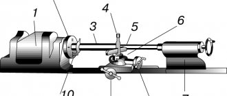
Main components of an internal grinding machine
Any internal grinding machine has the following components:
- headstock of the product;
In turn, the grandmother is divided into:
a) the headstock of the internal grinding machine. It provides both transverse and circular feed of the part. The front headstock support is a double-row roller bearing with a cone-shaped hole. The rear headstock support often consists of a pair of duplexed angular contact bearings. Also, the spindle assembly can be provided with several long spacer bushings with tightening and independent adjustment of the tension in the bearings, secured with separate nuts. The spindle drive is always carried out by overdrive flat toothed belts.
b) Tailstock, which has only adjustment movement, in order to be adjusted to a given machining length. This headstock has a quill into which the rear center is inserted. The quill can be moved by clamping and releasing the part.
- grinding head:
As a rule, the grinding head is one of the main components of the machine. It consists of a grinding wheel spindle with supports and a drive to it,
and hulls;
- table:
The table, placed along the guides, carries a grinding headstock;
- hydraulic table drive;
- bed.
Often, a headstock is installed on the bed, which is rigidly fixed and remains motionless.
Making your own machine
To create a machine with your own hands, you will need to initially understand what characteristics the machine should have, and then select a ready-made drawing or find a ready-made one in specialized literature.
Next, you need to create a cost estimate based on detailing, assess the need to manufacture original parts, or purchase ready-made analogues.
To create an internal grinding machine, you will need to prepare the following components and tools:
- the frame, which is the basis of the structure, the minimum size must be 180x160 mm, constructed of wood or steel plate;
- the base is made of thin sheet steel, the thickness of which is at least 0.5 mm; select a suitable electric motor, wiring, switch;
- purchase fasteners;
- construct steel guides for moving the frame;
- purchase handles for adjusting the position of the cutting disc relative to the workpiece; vice for fastening the workpiece;
- grinding disc;
- attachments for the grinding disc.
Note: in order for the working tool to move accurately relative to the workpiece, screw guides must be used. When the drum rotates, the disc will move smoothly inside the workpiece.
Internal grinder controls
The main controls of the internal grinding machine are:
- flywheel for changing the spindle speed;
- flywheel for manual transverse movement of the grinding head;
- fungus for turning on the fine radial periodic feed of the grinding wheel;
- flywheel for manual longitudinal movement of the table;
- handle for turning on the hydraulic drive of the table;
- handles for changing table speed;
- lever for retracting the table to the non-working position;
- push-button station;
- square for transverse movement of the headstock of the product;
- square for turning the headstock of the product;
- handle for hydraulic clamping of the product.
Movements in an internal grinding machine
The cutting movement of this machine is the rotation of the spindle associated with the grinding head combined with an abrasive wheel. The pair consisting of the spindle of the headstock of the product and the part is given a circular feed. Longitudinal feed is the reciprocating rectilinear movement of the table with the grinding headstock. Transverse feed is the periodic movement of the grinding head in the radial direction during the table stroke. Auxiliary movements may include movements of the workpiece headstock, manual movements of the table and grinding headstock.
Operating principle of internal grinding machine
In an internal grinding machine, the workpiece is fixed in a membrane or three-jaw chuck using a hydraulic clamp, the cylinder of which rotates with it, located at the left end of the spindle.
The release of the processed part is carried out by a special pilot. This release can only be reproduced with the extreme right non-working position of the machine table. The spindle of the product headstock is rotated, which corresponds to the selected circular feed speed. The grinding wheel, which is mounted on the spindle of the grinding headstock, can rotate at the highest speeds that correspond to the selected cutting speed.
When grinding a cylindrical hole, the spindle axis of the workpiece headstock is located parallel to the table guides. When grinding a conical hole, the workpiece headstock is installed in such a position that the spindle axis creates an angle with the table guides that is equal to half the angle of the hole cone. The headstock of the product rotates about its vertical axis in the form of a square.
The automatic operating cycle of an internal grinding machine is as follows. First, the processing of parts occurs in a rough grinding operation. After the rough grinding allowance has been removed at the command of the electrical measuring device, the table is moved to the extreme right position. After this, the grinding wheel is dressed. The slow speed of the table that occurs during straightening is set by a special throttle.
After finishing the wheel dressing, the automation panel switches the machine to the pure grinding mode. After finishing grinding, the measuring device sends a command to turn off the periodic cross feed and turns on a time relay, which can control the drying process. After the end of nursing, in a short time the table is moved to the right and stops. At this time, it is possible to release the hydraulic clamp of the part, then the hydraulic system is prepared to switch to the rough grinding mode of the next part.
Design and principle of operation
The internal grinding machine consists of:
Beds, racks. Spindle, work table, grinding disc, electric motor, controls or CNC unit, cooling system, housing, unit for securing the workpiece.
The principle of working on an internal grinding machine
The part is mounted in a three-jaw chuck, and a grinding wheel of suitable size and parameters is installed. Next, the machine is started. The circle is slowly inserted into the workpiece so that a certain part of the surface layer is removed. First, rough processing is carried out with the removal of large roughness, and then finishing. The number of passes of the circle inside the workpiece is determined by the requirements for the desired result, as well as the complexity of processing.
Specifications
Characteristics of machines for grinding internal surfaces:
diameters of machined holes from 6 to 800 mm;
engine speed from 12 thousand rpm. up to 80 thousand rpm;
electric motor power from 1.5 to 11.5 kW;
grinding head stroke length up to 500 mm;
workpiece rotation speed from 10 to 2000 rpm; grinding speed up to 35 m/s;
processing accuracy up to 1 micron;
disc roughness from 0.08 microns.
Properties of internal grinding machines.
1.The internal grinding machine is equipped with a feeding system and a compensation straightening system. They are two independent systems. After changing a new wheel there is no need to adjust the machine. A single processing cycle to control the final size of the workpiece.
2.The internal grinding machine is equipped with a jumping device, so there is no need for manual re-installation after measuring or straightening.
3. The work table is equipped with an axial micro-motion device to process the end surface with an internal grinding spindle. It is driven by hydraulics. Stepless speed control. There is a manual or hydraulic feed of the grinding wheel. The thyristor converter changes the spindle speed. The bed of the internal grinding machine has a machined surface for installing a steady rest to grind long workpieces.
4.The internal grinding machine is equipped with end surface grinding application. The rotating speed of the grinding spindle is 18000r/min. The largest internal diameter of the sanded product can reach 20mm.
List of main technical characteristics of internal grinding machines
Almost all models and types of internal grinding machines can be designed for processing metal products. Similar operations for processing wooden blanks are reproduced using other types of equipment. Therefore, the technical characteristics of internal grinding machines can only be calculated for processing large-sized products with the largest dimensions.
So, firstly, the maximum and minimum dimensions of the workpieces are determined. This can be attributed to the internal diameter of the hole, as well as the external dimensions of the workpiece. Next, you need to calculate the maximum permissible mass of the part. Secondly, you need to select the processing degree parameter from the following: end, internal or double-sided. Based on the above data, it is necessary to select the optimal model of an internal grinding machine.
Additionally, it is recommended to familiarize yourself with the following technical characteristics of the internal grinding machine equipment:
1.Maximum length of workpiece grinding.
v The grinding length may depend on the diameter of the workpiece. Often, the manufacturer indicates this parameter for maximum and minimum diameters;
2. Processing of cones.
v It is imperative to know:
- Allowable cone angle;
- Distance from the spindle axis to the worktable surface;
- The greatest distance from the end of the workpiece to the support cylinder of the spindle head;
- Electric motor power.
In most cases, this only applies to the drive of the main movement of the spindle head.
v The power of the coolant system and the lubricating element of the machine is taken into account;
3.Dimensions and weight of equipment:
For overall characteristics, it is imperative to know all the dimensions of the support platform and the dimensions with possible additional equipment;
4. An indicator of the accuracy of workpiece processing and the roughness of the prepared surface.
v Based on these indicators, it is necessary to select the most optimal equipment option. Also, it should be taken into account that for processing large-sized products you will need special installations that are necessary for installing the fastening block. This condition is mandatory only when the mass of the workpiece significantly exceeds 20 kilograms.
The detailed technical characteristics of the internal grinding machine can be viewed on the RIG-150СNC model, since this machine is in demand:
- Maximum Grinding Hole Diameter (mm) – 6~150;
- Maximum Length of Grinding Hole (mm.) – 150;
- Diameter of processing over the bed (mm.) –520;
- Processing Diameter with Installed Chuck Protection (mm.) –320;
- Maximum Table Movement (mm.) –540;
- Table Movement Speed (m./min.) – 27
- Speed of movement of the hydraulic table (m/min) – 7.2;
- Speed of movement of the hydraulic table along one of the axes (m/min) – 20;
- Spindle Rotation Speed (rpm) – 0~800;
- Working Feed Speed of the Spindle Head (mm./min.) – 50;
- Accelerated Movement along the X Axis (m/min.) – 6;
- Minimum Step Value along the X Axis (mm) – 0.001;
- Minimum Step Value along the Z Axis (mm) – 0.001;
- Headstock Rotation Angle (degrees) Right – 13°;
- Headstock Rotation Angle (degrees) Left – 5°;
- Distance from the Spindle Center to the Floor (mm.) – 1060;
- Adjustable Grinding Spindle Length (mm.) – 100;
- Feed: Automatic hydraulic, stepless, automatic, servomotor;
- Headstock Motor Power (kW) – 0.75;
- Power of the Servomotor for Feeding the Spindle Head (W) – 400;
- Grinding Head Motor Power (kW) – 1.5;
- Hydraulic Pump Power (kW): First axis – 1.5 / Second axis – 0.75;
- Coolant Pump Power (kW) – 0.09375;
- X-Axis Servomotor Power (kW): First axis – 0.6 / Second axis – 0.9;
- Power of the Z-Axis Servomotor (kW) – 2;
- Hydraulic Tank Capacity (liter) – 90;
- Coolant tank capacity (liter) – 80;
- Area (mm.) – 2600 x 1430;
- Machine height (mm.) – 1400;
- Machine weight (kg) –2600.
About cylindrical grinding devices
In any CNC grinding machines, the greatest effect produced is achieved when processing surfaces with one installation of special multi-stage parts, for example:
- spindles for securing workpieces;
- electric motor shafts;
- turbine elements;
- rotational frequency control gearboxes.
In such cases, productivity increases significantly by reducing the extra time that is allocated to:
- installation of the required blanks and removal of already processed finished products;
- reinstallation for the purpose of subsequent processing of the shaft journal;
- necessary measurements.
On these numerical cylindrical grinding machines, the programmed processing of various multi-stage shafts reaches the end with a reduction of time of almost 1.5-2 times when compared with a conventional control machine.
Setting up internal grinding machines
Significant stages in each machine are mastering the manual for the operation of this machine, safety measures when handling the machine, working on it, as well as monitoring the operation of absolutely all controls and locking devices of this machine. Before starting to work on the machine, it is necessary to lubricate all the required parts of the machine in accordance with the lubrication frequency schedule, and also check the suitability of the coolant and the condition of the machine controls. As a rule, the setup of machines begins by checking the location of the headstock of the product.
First of all, you need to install the first part, then grind all the necessary working jaws, installing them at a distance that becomes equal to the outer diameter of the surface of the clamped part, taken by the base. In addition, it is necessary to grind the surface of the faceplate using a cup-type wheel or a G1B-shaped wheel. The size of the circle is used in accordance with the diameter of the hole of the part that will be processed, and the properties of the circle are selected in connection with the required surface qualities and accuracy of the hole, established by the drawings of the part.
After securing the workpiece in the chuck, it is necessary to install the table stops so that when the table moves to the right and left, the exit of the grinding wheel from the workpiece is equal to 1/3-1/2 of its width. When setting up to process parts of different shapes and lengths, it may be necessary to move the grinding head along the table. To do this, it is necessary to connect the headstock to the bridge with a special bar and the flywheel of the manual table movement mechanism moves the table relative to the headstock.
To ensure safe operation of the machine, it is necessary to install the sliding protective cover of the product so that it completely covers the part. For each grinding wheel it is necessary to select the appropriate replacement guard.
First, the dressing mechanism is adjusted in the longitudinal direction, placing the diamond from the end of the part at a distance equal to the width of the circle plus 15-20 mm. In the transverse direction, the top of the diamond is set along the generatrix of the grinding wheel when it touches the surface of the hole being processed. The top of the diamond must lie in a plane passing through the axes of the grinding wheel and the hole being processed. This is achieved by adjusting the diamond holder stop.
In order to make the first wheel edit, you must perform the following steps:
- Turn on the machine (the signal light should light up);
- Move the table to the extreme right position;
- Turn on the electric motor of the hydraulic system and together with it the coolant pump;
- Insert the grinding wheel into the grinding zone by turning the “START” handle and reversing the table;
- Check the table stroke length when grinding;
- Use to adjust the speed of table movement;
- By turning the reverse handle to the right, bring the wheel into the straightening zone, checking that the length of the table stroke is correct when straightening;
- Use the throttle to adjust the speed of the table when editing;
- Turn on the rotation of the internal grinding spindle;
- Set the cross feed mechanism handle to the “Slow movement” position.
- Correct in several strokes using the cross-feed flywheel.
Features of operation of internal grinding machines
As a rule, the operation of any metalworking equipment begins with choosing the correct installation plan for the machine. First, you need to prepare a site for installation, taking into account the weight and dimensions of the machine. Also, it is additionally necessary to take into account the impact on the slab in the form of vibrations that occur during operation.
Next, you should calculate all the necessary parameters of the connected electrical network. To do this, you need to know the maximum power consumption of the machine. Based on these values, electrical wiring with the appropriate cross-section is selected. An RCD and ground loop must be installed.
When carrying out work on an internal grinding machine, you must adhere to the following rules:
1.Preparation of equipment.
- After a long period of inactivity, it is necessary to inspect all components and assemblies. The machine starts only in idle mode and without installing a workpiece. The correct operation of the lubricating and cooling system and chip removal must be checked;
2.Staff.
- Before starting work on the machine, personnel are required to undergo a training course, which includes studying the design of the machine, as well as familiarization with the rules of operation of the machine and safety precautions;