Radiography of welded joints is a non-destructive testing method. Radiographic testing is designed to detect in welded joints:
- lack of penetration;
- cracks;
- various inclusions;
- since then.
The method is also used to assess the amount of concavity and convexity of the root of the seam, to identify undercuts and burns that are inaccessible for visual inspection.
The essence of the method
The radiography method involves obtaining a shadow image of a welded joint by illuminating it with X-ray or gamma radiation. The goal is to study the internal structure of the control object.
The special properties of X-ray and gamma radiation are associated with their different absorption and penetration when passing through different media, depending on the type of material, its thickness and radiation energy. These properties are used in flaw detection of welded products.
The essence of the radiography method is the phenomenon of blackening of the X-ray film emulsion, caused by the property of radiation that is of an electromagnetic nature. The degree of blackening of a particular area of the film after its photoprocessing depends on the number of photons, which is determined by the attenuating ability of the sample being illuminated.
Radiographic images obtained as a result of radiography, depending on the method of transillumination, are called:
- radiograph (x-ray radiation);
- gammagram (gamma radiation).
The shadow pattern visible in the image is the distribution of the attenuation power of the compound exposed to transillumination.
Advantages of the method:
- high sensitivity , allowing to detect minor defects;
- objectivity of the results obtained;
- the ability to determine the depth of the defect and its linear dimensions.
Flaws:
- low control performance;
- high consumption of reagents and film.
Radiography of a weld: what it reveals and how it is done
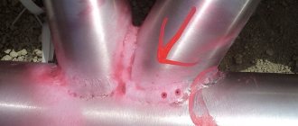
Radiography is a non-destructive testing method that allows you to determine the presence of internal defects in the base metal. This is the most accurate and objective study, thanks to which the quality of the seams of metal structures and parts is confirmed. Radiographic testing consists of the following: X-ray radiation is directed at the connection being tested, and on the reverse side there is a film sensitive to X-ray rays. Various weld defects absorb rays worse than homogeneous metal, appearing on the film in the form of light spots. The shape and size of welding defects are judged by their outlines and sizes.
GOST
Requirements for the quality of joints formed by welding are specified in regulatory and technical documents. The radiographic method of non-destructive testing of welded joints is regulated by GOST 7512-82 “Non-destructive testing. Welded connections. Radiographic method".
The document contains:
- General provisions.
- equipment requirements.
- Information regarding preparation for control.
- Control circuits.
- Selecting radiography parameters.
- Decoding images.
- Safety regulations.
- Metrological support.
GOST has 6 annexes.
GENERAL PROVISIONS
1.1. Radiographic testing is used to detect cracks, lack of penetration, pores, slag, tungsten, oxide and other inclusions in welded joints.
1.2. Radiographic testing is also used to identify burns, undercuts, and assess the magnitude of convexity and concavity of the root of the seam, which are unacceptable for external inspection.
1.3. Radiographic monitoring does not reveal:
- any discontinuities and inclusions with a size in the direction of transmission of less than twice the control sensitivity;
- lack of penetration and cracks, the opening plane of which does not coincide with the direction of transmission and (or) the opening value is less than the values given in the table. ;
- any discontinuities and inclusions, if their images in the photographs coincide with the images of foreign parts, sharp corners or sharp changes in cracks of the metal being scanned.
1.1 — 1.3. (Changed edition, Amendment No. 1).
Table 1
mm
| Radiation thickness (according to GOST 24034) | Opening of lack of penetration (cracks) |
| Up to 40 | 0,1 |
| St. 40 » 100 incl. | 0,2 |
| » 100 » 150 » | 0,3 |
| » 150 » 200 » | 0,4 |
| » 200 | 0,5 |
1.4. Radiographic testing is carried out on welded joints with a ratio of the radiation thickness of the deposited weld metal to the total radiation thickness of at least 0.2, which have two-way access, allowing the installation of a cassette with radiographic film and a radiation source in accordance with the requirements of this standard.
Required equipment
Depending on the method, different types of equipment are used.
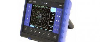
X-ray machines
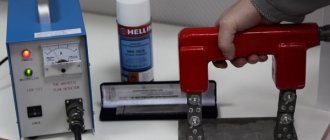
To obtain an x-ray, the following equipment is required:
- x-ray machine;
- defectometer.
Device design:
- x-ray tube;
- high voltage generator;
- Remote Control.
Gamma devices
The device is a radioisotope flaw detector consisting of the following elements:
- radiation head with radioactive isotope;
- power supply drive;
- ampoule tube;
- Remote Control.
Gamma control is performed using artificial radioactive isotopes iridium 192, thulium 170, cobalt 60. The isotopes are stored in special containers.
Advantages compared to the X-ray method:
- the container with the isotope is small in size , which does not require much space for its placement and is convenient for field conditions;
- Gamma rays allow simultaneous monitoring of several parts;
- The method is applicable to obtain a gammagram of a circumferential weld of a welded product;
- the costs of carrying out are lower than the x-ray method;
- The service life of the drug cobalt 60 is more than 5 years.
The disadvantage of the method is that the sensitivity to detecting defects in seams less than 50 mm thick is lower than when using an X-ray machine.
Other equipment
When inspecting products with a cross section of 70 mm or more in radiation flaw detection, linear accelerators, betatrons and microtrons are used.
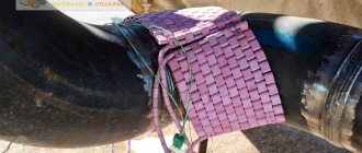
Auxiliary elements:
- Radiographic film is a means of recording radiation.
- Reinforcing fluorescent and metal screens - to reduce transillumination time.
- Sensitivity standards - determination of the relative sensitivity of radiographic control.
- Cassettes, holders, lead markings.
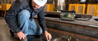
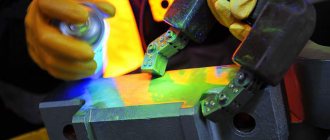
Execution algorithm and security measures
Work to identify defects and deviations using the radiation method is regulated by GOST 7512-86 and is carried out step by step by laboratories certified in accordance with PB 03-372-00 and PB 03-440-02:
- Preparing an object for x-raying by cleaning its surface from debris and rust
- Visual inspection with marking and marking of areas of the object for further research
- Controlled welds are placed between the emitter and receiver of the device
- The equipment is turned on after a preliminary check of its functionality
- X-rays penetrate through the seam and are received by a sensor located on the back side
- The obtained information is displayed on a monitor or x-ray film for further analysis and storage
The level of sensitivity of devices depends on many factors. It is checked by placing various sensitivity standards in the controlled area in a given sequence:
- Wire
- Grooved
- Lamellar
Work related to the RK is carried out in compliance with safety rules, providing for:
- Availability of a technological map (with an algorithm of actions, cassette charging schemes, standards)
- Preliminary check of equipment serviceability
- Shielding of the equipment involved to prevent the spread of radiation hazardous to people and the environment
- Maintaining a safe distance between specialists and the equipment used in their work
- Maximum reduction of time spent by specialists in potentially dangerous places
- Use of PPE
- Fencing the work area, determined using DKS-AT dosimeters, with special tape and signs
The area intended for radiation monitoring activities must be equipped with a protective coating (lead sheets) and cleared of unauthorized persons.
Certification and training of non-destructive testing specialists
METROLOGICAL SUPPORT
8.1. Groove and plate sensitivity standards used for control must be subject to metrological verification upon their release and subsequent verification at least once every 5 years. When releasing these standards, the trademark of the enterprise that produced the standard and the year of issue must be applied electrochemically to the reverse side of each standard; during the next verification - the trademark or symbol of the company that carried out the verification, and the year of verification.
8.2. Wire sensitivity standards are not subject to verification, however, they must be removed from circulation if the plastic cover is damaged or traces of corrosion of the standard wires are detected during visual inspection.
8.3. Densitometers and sets of optical densities used to determine the optical density of images are subject to verification at least once a year with the obligatory execution of a document (certificate) on the verification results.
8.4. X-ray cameras are subject to verification only upon their release, with the obligatory indication in the passport (certificate) of the X-ray viewer of the maximum brightness of the illuminated field and the optical density of the image.
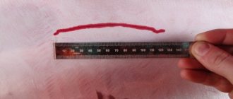
8.5. Measuring instruments used to determine the size of images of cracks, lack of fusion, pores and inclusions in photographs (measuring rulers and magnifying glasses) are subject to verification in accordance with the current provisions applicable to these instruments.
8.6. Non-standardized measuring instruments used to determine the size of images of cracks, lack of fusion, pores and inclusions in images (measuring templates, stencils, etc.) must be verified at least once a year with the obligatory execution of a document on the verification results.
Sec. 8. (Introduced additionally, Amendment No. 1).
Thickness of metal reinforcing screens
Table 1
| Radiation source | Screen thickness, mm |
| X-ray machine with X-ray tube voltage up to 100 kV | Up to 0.02 |
| X-ray machine with a voltage on the X-ray tube over 100 to 300 kV | 0,05 — 0,09 |
| X-ray machine with X-ray tube voltage over 300 kV | 0,09 |
| 170Tm | 0,09 |
| 75Se; 192Ir | 0,09 — 0,20 |
| 137Cs | 0,20 — 0,30 |
| 60Co | 0,30 — 0,50 |
| Electron accelerator with radiation energy from 1 to 15 MeV | 0,50 — 1,00 |
Methods for charging cassettes
table 2
| Charging method | Availability of films in the cassette | |
| one | two | |
| No screens | ||
| With reinforcing metal screens | ||
| With intensifying fluorescent screens | ||
| With reinforcing metal and fluorescent screens | ||
- radiographic film;
— reinforcing metal screen;
— intensifying fluorescent screen.
SAFETY REQUIREMENTS
7.1. The main types of danger for personnel during radiographic control are exposure to ionizing radiation and harmful gases formed in the air under the influence of radiation, and electric shock.
7.2. Radiographic monitoring and recharging of radioactive sources must be carried out only using equipment specially designed for these purposes and in good condition, documentation for the manufacture and operation of which, when produced in quantities of more than three copies, must be agreed upon with the USSR State Committee for the Use of Atomic Energy and the Main Sanitary -epidemiological department of the USSR Ministry of Health; up to three copies - with local sanitary and epidemiological service authorities.
7.3. The electrical equipment of existing stationary and portable installations for radiographic testing must comply with the requirements of GOST 12.2.007.0 and the “Rules for the Construction of Electrical Installations” approved by the Main Technical Directorate for the Operation of Power Systems and the State Energy Supervision Authority of the USSR Ministry of Energy.
7.4. When carrying out radiographic monitoring, storage and recharging of radioactive radiation sources, work safety must be ensured in accordance with the requirements of the “Basic Sanitary Rules for Working with Radioactive Substances and Other Sources of Ionizing Radiation” OSP-72/80 No. 2120-80, approved by the Chief State Sanitary Doctor of the USSR January 18, 1980, “Radiation Safety Standards” NRB-76 No. 141-76, approved by the Chief State Sanitary Doctor of the USSR on June 7, 1976, “Sanitary Rules for Radioisotope Defectoscopy” No. 1171-74, approved by the Deputy Chief State Sanitary Doctor of the USSR August 7, 1974 and GOST 23764.
7.5. When operating stationary and portable installations for radiographic testing connected to an industrial electrical network, the safety of work must be ensured in accordance with the requirements of the “Rules for the technical operation of consumer electrical installations” and the “Safety Rules for the operation of consumer electrical installations,” approved by Gosenergonadzor on April 12, 1969.
7.6. When transporting radioactive radiation sources, the requirements of the “Safety Rules for the Transportation of Radioactive Substances” PBTVR-73 No. 1139-73, approved by the Chief State Sanitary Doctor of the USSR on December 27, 1973, must be observed.
7.7. Enterprises performing radiographic testing of welded joints develop, in accordance with the safety requirements of this section, documentation defining the rules and methods for the safe organization of work, the scope and means of radiographic testing, taking into account local production conditions, and communicate them in the prescribed manner to workers.
Thickness of protective lead screens
| Radiation source | Screen thickness, mm |
| X-ray machine with X-ray tube voltage up to 200 kV | Up to 1.0 |
| 170Tm; 75Se | Up to 1.0 |
| X-ray machine with X-ray tube voltage exceeding 200 kV | From 1.0 to 2.0 |
| 192Ir; 137Cs; Co | From 1.0 to 2.0 |
| Electron accelerator with radiation energy from 1 to 15 MeV | St. 2.0 |