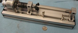
In today's review, the author will share with us his personal experience of making a homemade mini lathe.
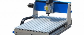
The basis of the machine is a square profile pipe 60x60 mm (wall thickness - 3 mm).
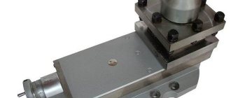
The dimensions of the professional pipe were not chosen by chance - it ideally fits a clamping chuck with a diameter of 16 mm. The result is a fairly compact headstock.
If you use a drill chuck with a diameter of 13 mm to make the headstock, then in this case you will need to use a 50x50 mm profile.
We also recommend reading: how to make a simple and compact machine for making clamps for reinforcement cages.
The length of the lathe bed is 22 mm, but if necessary it can be made longer.
Application areas of lathe
A lathe is an ancient device; it is an early device for processing a wide variety of parts from a wide variety of materials - from metal to wood, etc.
Processing is, first of all, turning surfaces both inside and outside, drilling and boring holes of different diameters, cutting threads, and forming surface relief using knurling.
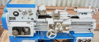
If we talk about turning metal parts, then industrial turning devices produced by different factories are expensive and massive units, which are very difficult to operate.
They in no way relate to desktop devices; these are serious industrial units that, in principle, are not suitable for handicraft work. Therefore, a DIY lathe is a great idea by all accounts.
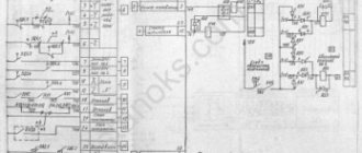
Drawing of a lathe.
You can, for example, make it in the form of a mini version, which will be quite enough for processing both metal parts and workpieces made of any other materials.
There are certain limitations when using homemade mini-machines: they are designed mainly for working with round parts, with sections such as axles, handles for tools, wheels, etc.
In mini-machines, parts need to be fixed only in a horizontal position for their rotational movements. Excess material during turning is removed by cutters, which are fixed in the support of the lathe.
Purpose and capabilities
A modern lathe is a symbiosis of mechanical parts and electronic components
The main functions of any modern mechanism, be it a simple manual meat grinder or a coal miner, are provided by rotating parts that would be impossible to produce without lathes. A special feature of these units is the processing of rotating bodies by cutting. Lathes provide precision manufacturing that is unattainable with other metalworking methods. Equipment of this type is easy to automate and allows you to perform the following operations:
- longitudinal turning of a smooth or stepped cylindrical surface;
- processing of ledges and grooves;
- turning of external and internal conical surfaces;
- boring of conical and cylindrical holes;
- cutting threads (internal or external) with a cutter or drill;
- reaming and countersinking of holes;
- groove cutting or cutting;
- shaped turning;
- knurling of a corrugated surface.
The main purpose of lathes is to process three types of parts - shafts, bushings and disks, resulting in a variety of axles, flywheels, liners, sprocket blanks, etc. In addition, other workpieces with the shape of bodies of revolution are processed on universal units, for example , body parts.
Screw-cutting lathes are the most popular design among home craftsmen
All existing lathes are distinguished by:
- according to turning characteristics (turret lathes, rotary lathes, multi-cutting machines, etc. - a total of nine subgroups);
- size range, which depends on the diameter of the workpiece;
- degrees of specialization (special, universal, etc.);
- accuracy class.
The most popular for repetition at home are screw-cutting lathes, which have the simplest design among the units presented above.
Components of a mini metal lathe
The composition of any turning device is traditional; all of the following elements are present regardless of how it is made - manually at home or industrially.
The devices consist of the following components:
bed
The main load-bearing element of the entire structure, giving it rigidity and strength. The bed of a homemade metal lathe is made from wooden beams or metal blanks in the form of ready-made corners.
The main requirement for the bed is the necessary strength, since the structure of the machine is exposed to strong vibration during the processing process.
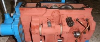
Drive unit
The main element of the part responsible for the power of work. The drive must be selected very correctly based on the power required. This is not an easy task and one that needs to be thought through carefully.
A used drive from a washing machine, a construction mixer, or something else will suffice if you are making a lightweight machine for metal work.
The number of revolutions with such drives is about 1500 rpm, and the power is 200 W or slightly higher.
- Tailstock. This is a special steel plate to which a steel corner is also welded. It is needed for tight fixation of the workpiece to the bed for high-quality processing.
- Headstock. This is the same part as the tailstock, but unlike the front one, it is fixed on the movable frame of the device.
- Front and back centers.
- Caliper.
This is one of the key factors for the working elements of the device, information about which you can read below.
What is needed for making
The ideal option when making a homemade lathe would be to use separate components from decommissioned equipment. If this is not possible, then you will have to make components and parts yourself.
Instead of a cast frame, a frame welded from steel profile pipes and angles is used. It goes without saying that a wooden frame is not an acceptable option in this case. The metal profile can provide the required rigidity and stability of the structure. In addition, with the help of even square and rectangular pipes, it is not at all difficult to adhere to the strict geometry of the frame. An uneven frame will not make it possible to correctly fix the centers, which will subsequently affect the quality of the work performed.
Low-power asynchronous motor - an excellent power unit for a homemade design
For the drive you will need a power unit. It is best to use a low-speed asynchronous electric motor. Unlike collector units, “asynchronous” units are practically not at risk of breakdown when the speed drops sharply.
To process workpieces with a diameter of no more than 100 mm, an electric motor with a power of 500 - 1000 W will be sufficient. If you plan to grind larger parts, you will need at least a 1.5-kilowatt power unit.
In addition, you will have to select a drive belt (or several belts of different lengths). Don’t forget about the fasteners that will attach the individual units to the body. For a homemade lathe, nuts and bolts with a diameter of 8 and 10 mm with regular metric threads are suitable.
Parts machined from a steel bar and then hardened are used as slides, but the best option would be guides made from shock-absorbing struts or long shafts of industrial mechanisms. They have excellent geometry, and their surface is hardened in the factory.
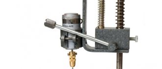
The tailstock, like the spindle, is best used from decommissioned factory equipment
The tailstock can also be made from profile pipes and a thick metal sheet, but the quill is made from a hardened pointed bolt, several nuts with the same thread and a steering wheel made from a pulley from agricultural machinery. Using a homemade quill will require lubricating the contacting surfaces with lithol or grease every time you attach a part. A similar procedure will not be necessary with a factory-made rotating center, so if possible, it is better to buy this part.
The longitudinal and transverse feed screws can also be turned on a lathe or you can use a long threaded rod, which can be bought in construction hypermarkets.
For feed screws, a fine-threaded shaft is used - this will significantly increase the positioning accuracy of the working tool.
For rotation units, you will need rolling bearings installed in the housing, and pulleys of various diameters mounted on the drive shaft will allow you to regulate the speed. These parts can be bought or ordered from a familiar turner.
Making a caliper will require stocking up on a steel plate with a thickness of at least 8mm. It can also be used for a tool holder.
Another component that cannot be made in a home-made environment is the spindle. You'll have to buy it. Mounting the spindle requires the manufacture of a shaft on which the driven pulleys will be mounted. The strength of this part must be impeccable, so it is best to use parts from discarded factory mechanisms.
There are designs that do not have a belt drive. Rotation from the motor shaft is transmitted directly to the spindle. Of course, they have a right to exist, however, when choosing such a scheme, be prepared for frequent failure of the electric motor bearings.
In addition to the lathe, during the work you will need the following tools and equipment:
- welding machine;
- Bulgarian;
- grinding and emery machine;
- electric drill and set of metal drills;
- taps and dies for thread cutting;
- set of wrenches;
- caliper, metal ruler;
- marker.
All these tools and materials will allow you to make a full-fledged tabletop lathe. If you couldn’t get some parts, don’t despair - they can be replaced with something else for a while. Thus, a chuck from an electric drill can be used instead of a spindle if small workpieces need to be processed.
How is rotation done?
The device of a lathe.
Torque is generated in the machine in different ways. You can install the working part on the rotary shaft of the electric motor directly. This approach will save a lot of things: both space and money for spare parts.
Unfortunately, such an arrangement is not always possible, so the so-called gears are appointed as the main executor of the rotational movement. They come in chain, belt and friction types.
Each type of transmission has its pros and cons:
Belting
The most budget-friendly transmission option for a motor with many advantages. The main one is reliability. Making a belt drive is simple: most often craftsmen take one from other devices.
There is also a drawback - this is its fragility, since the belts wear out quickly. You will have to change them quite often.
Chain and friction transmission
A chain drive is not cheap, and it is also much more bulky than a belt drive. But such a transmission will last much longer, so you will get “strategic” cost savings. The friction drive is located exactly in the middle between the belt and chain drives.
What can be done with a mini-lathe, and where is it used?
Household mini-lathes, like similar industrial equipment, are designed for processing metal workpieces and giving them cylindrical, conical and spherical shapes. Nowadays, almost all industries use CNC units, which makes it possible to reduce human participation to almost zero, but for home needs a simple machine is suitable. Despite the fact that compact turning equipment has inherited most of the functions from its larger counterparts, however, it can only be used to process small workpieces and parts. Also, on mini-machines you can perform end cutting and drilling, perform external and internal threading, boring and much more. Compact turning equipment is perfect for a garage, home, installation on a balcony or in a small workshop.
Tabletop metal lathe
Main components of the device
The final quality of the processed part depends on the support. The effort, time and all other resources invested in the process can go down the drain without a well-established support. This part is located on special “sleds” moving along the frame along guide vectors.
The movement of the caliper can occur in the following directions:
- Longitudinal movement in which the working element of the device moves along the part being connected. This direction is performed when turning a circular thread or to remove the surface layer of paint or something else from the workpiece being processed.
- The transverse movement of the caliper is perpendicular to the axis of the part. With the help of this movement, holes and recesses are made.
- The inclined movement can be carried out at various angles of inclination, it is used to produce surface recesses of various configurations.
It should be remembered that the caliper, as the most active and moving part of the device, is the most worn.
Elements of a lathe.
Rapid wear is explained by the action of constant and serious vibration, which results in loosening of the fasteners and subsequent backlash, which always affects the quality of turning work in one form or another. Such a disaster can be avoided; this requires constant adjustment and adjustment of the caliper.
The caliper can be adjusted in different ways. If the backlash is adjusted, it is eliminated using a screw. Gaps can be eliminated using special inserts between the carriage and the guides.
Gaps appear when the screw, which controls longitudinal and transverse movements in planes, wears out. Oil seals can also wear out. In this case, they are washed and lubricated until completely saturated with machine oil. Sometimes they just need to be replaced with new ones.
Machining on lathes, diagrams and drawings
Briefly about the control system, we can say that if knowledge and skills in engineering radio modeling allow, you can always make a simple screw-cutting lathe or lathe-milling machine with numerical control. CNC lathes allow you to automate the same type of work and they are needed if the master has to make a large number of identical workpieces according to a template.
For the most part, desktop machines are designed to perform one-time work, so the use of complex programming systems is hardly justified on machines with a low degree of accuracy.
Stages of assembling a lathe
Homemade metal lathes are assembled with your own hands quickly and in an uncomplicated manner. The only thing that needs to be strictly followed is the assembly order.
A homemade lathe must be assembled with maximum precision:
- The first step is to assemble the frame from metal elements. It is better if these are channels and beams. It is necessary to calculate the load for the planned work: what size parts are you going to deal with? If, for example, you plan to process metal objects longer than 5 centimeters, the metal frame of the machine must be more than 3 centimeters thick.
- Installation of longitudinal shafts with guides on channels. It is better to fix the shafts with welding units, but they can also be secured with bolts.
- Preparing the headstock from a thick-walled hydraulic cylinder with two bearings pressed into the cylinder body.
- Shaft routing using large diameter bearings.
- Pouring lubricant into the hydraulic cylinder.
- Installation and fixation of the pulley with caliper and guides.
- Electric drive installation.
Don’t forget to use a special tool rest for good stability of the cutters for the metal lathe. A metal turning tool is one of the key elements; we work with it carefully and carefully.
Attach a metal strip with a protective function to the bottom of the machine structure - it will prevent the working part of the machine from deforming during activity.
Purpose of the equipment
In the technology of processing materials by cutting, it is customary to distinguish processing installations by accuracy classes. The main criterion is the material that needs to be given certain shapes and parameters:
- Wooden blanks are turned on machines that provide accuracy up to 1 mm.
- Structural steel products are sharpened with an accuracy of 0.05 mm.
- On high-precision machines (processing products made of tool steels) equipped with micrometric measuring tools, it is possible to achieve performance up to 0.005 mm.
Woodworking equipment is created for home use, and if it is necessary to work on metal blanks, metal machines are needed. The main differences are in the drive for the tool.
If you need to turn a wooden part, use a stop. The tool is rested on it. Longitudinal and transverse feeding is performed manually.
When processing metal, you have to counteract significant resistance forces. It is quite difficult to hold the cutting edges with your hands. Therefore, auxiliary devices are used that help stabilize the position. Machine tool builders have a concept of AIDS strength.
This abbreviation is deciphered as follows: machine, fixture, tool, part. All these elements must maintain a certain rigidity, then the required accuracy during processing is guaranteed.
Which motor is better
Assembly drawing of a lathe.
The electric motor is a key part of any metal lathe. The movement of the working part of the apparatus occurs thanks to it and nothing else. The more powerful the motor, the more powerful the machine itself.
The power level of the motor must be calculated depending on the planned work - the size of the metal parts that you are going to work with on your new unit.
If you plan to work with small parts, a motor with a power of about 1 kW will be sufficient. Such motors are found on sewing machines or other household electrical appliances. If your future parts are larger, choose a motor with a power of 1.5 to 2.0 kW.
The power also depends on the material you are going to work with. If, for example, your material is wood, then DIY wood lathes, including a homemade wood lathe cutter, will not require much power.
The most important issue is reliable insulation of all electrical components. The best option would be to consult a specialist. Confidence in the safety of the device and the professional reliability of the design will not hurt you: after all, you are going to work with electricity and metals. And they don't joke with them.
The concept of a lathe: device and types
If you think that lathes are the destiny of the new world, then you are deeply mistaken. The first variations of the design saw the light of day in Ancient Egypt, more than 1,200 BC. Artifacts from Italy of the 6th century BC also show signs of being worked on lathes, which local residents made with their own hands based on the simplest principles of mechanics.
Mentions of turning equipment appear in Turkey, China and other prosperous civilizations that existed before our time. Jacques de Vaucanson managed to assemble the first metal lathe with his own hands in 1751. As industry developed in the 19th and 20th centuries, the design of equipment gradually increased in size, strength and weight, turning into the semblance of modern assemblies that people see in industrial production and in hardware stores.
Although the Russian market is overcrowded with metal cutting machines of various subtypes, their general arrangement of components is approximately the same. In order to understand how to make a lathe with your own hands, you need knowledge of the design of the equipment and its most important components. You can understand the issue in more detail using the table below.
| Knot | Description |
| bed | A fixed structural element of a lathe, based on 2 vertical ribs. There are 2-3 crossbars between the ribs, which provide rigidity and fixation of the stator. The longer the lathe, the greater the number of cabinet legs (the design provides for storing small tools in them). The slats running across are guides for the headstock and caliper. |
| Headstock | The task is to support + rotate the element during processing on the machine. This unit also contains elements for adjusting the rotation speed of the structure - a spindle, two bearings, a pulley and a speed box. The accuracy of the processing of parts generally depends on the condition of the headstock. |
| Spindle | Previously, the part was produced monolithic, but in 2022 priority is given to hollow options. A controversial decision, because the part is constantly pressed by the mass of the workpieces, the pressure of the belt and the pressure of the cutter. The front of the spindle is cone-shaped, and its stability is ensured by bearings and a tension control mechanism. The rotation itself comes to the spindle from an electric motor through a high-speed gearbox and a belt. |
| Feed mechanism | The unit gives the direction of movement for the unit support through a snaffle, which is located in the headstock. The part is adjusted through the external handles of the lathe. An additional adjustment parameter is the rotation amplitude. Changes are corrected by changing gears with different numbers of teeth. |
| Caliper | A movable structural element with a platform for attaching cutters for processing a workpiece. The complex design of the mechanism allows it to move in 4 directions relative to the central axis of the machine. Vertical/horizontal feeding occurs on a skid. The lower slide is the base of the rotating part and is designed to adjust the angle of the workpiece for the apron of the structure. |
| Apron | The hiding part of the structure, behind which there are components for powering the machine (caliper, rack and pitch screw). The handles for controlling the unit are located to the outside - this makes it easier to regulate the movement of the caliper. |
| Tailstock | The moving part of the device, which is responsible for securing the workpiece to the spindle. It has 2 parts - a base tile and an upper one that directly holds the spindle. The front part moves along the bottom perpendicular to the horizontal axis of the machine. This layout is required for working out cone-shaped workpieces. The headstock is attached to the frame using regular bolts. |
It is important to understand that most lathe models are individual in their layout, but the components described above are available in 98%+ of small and medium-sized metalworking equipment. Having studied the drawings of metal lathes on the Internet, which you are supposed to do yourself, you will independently verify the correctness of our statement.
Now a few words about the classification of lathes. Depending on the shape, format and specification, equipment is usually divided into 8 categories. More details on the issue are described in the table below.
| View | Description | Popularity (out of 5 ★) |
| Lathe-screw-cutting | Suitable for non-ferrous and ferrous alloys/metals. By its design, it is one of the universal types of equipment. The main capabilities are cone sharpening + metric/inch and other types of threading. Within the category there is a classification according to the level of accuracy - “N”, “P”, “B”, “A” and “C”. The first ones are normal accuracy (most of the equipment produced), and “C” are master machines with the highest levels of accuracy in their work. | ★★★★ |
| Lathe-rotary | The key difference is that the rotation axis is located vertically. The equipment is used for any operations involving metal and wood – turning, boring, slotting, carving, etc. If the equipment is equipped with auxiliary units, we get a milling or grinding machine. | ★★★★★ |
| Lobototurny | The rotating axis is located high, and the bed is short in length. The intended purpose is turning workpieces with a large radius and a small length. 70% of models do not have a headstock at the back. | ★★★ |
| Turning and turret | A highly specialized machine that is used on calibrated rods. In terms of functions, everything is standard - drilling, threading, boring, and the like. | ★★ |
| Automatic longitudinal turning | The unit is used for mass industrial production of small pieces of wire or shaped profiles. For metals, the choice of processing is also wide - from pure copper to alloy steels. The machine supports the ability to install CNC. | ★★★ |
| Multi-spindle lathe | Another option for highly specialized equipment for high-precision processing of workpieces from rods of various sections or pipes. They have high productivity + are able to perform most turning operations. | ★★★ |
| Turning and milling centers | Equipment that combines 2 directions – turning and milling. The second point is realized thanks to a special milling head and spindle used for both rotating and static tools. | ★★★★ |
| CNC machines | Expensive universal variations of equipment with software. In 95% of cases they are used for industrial production and processing of parts. | ★★★★★ |
A lathe is an indispensable thing in everyday life. Yes, for city dwellers who are far from metalworking, such a device is not so necessary in the garage (it will only take up space), but if we are talking about agriculture (the same as farming), then fitting parts without using such equipment is physically impossible.
Important: a mini lathe is ideal for home use. Building it with your own hands will not be a problem even for a beginner in metalworking, and the difference in money compared to the purchase price of the equipment will exceed 400%.
Depending on the target need, you should pay attention to rotary, tabletop, screw-cutting and combined lathes with manual control. It makes no sense to spend money on a CNC and add unnecessary pain to installing/configuring it if you assemble the equipment yourself from scratch.
3 step-by-step instructions on how to make your own vise
Making a machine from a drill
The drill will look great as a drive to a lathe.
This elegant solution will save you a lot of money and make your life much easier because it has a number of great benefits:
- The modularity of the device: it is simply assembled and disassembled. The drill can be detached from the frame and reattached without any difficulty.
- This model is very transportable, you can work with it anywhere - even in the country, even in the garage.
- Significant cost savings: no need to purchase additional replacement attachments or belt drive.
To assemble a device from a drill, you will need almost the same parts as for a regular device. Only two things will not be needed: an electric motor and a headstock, and these are the most important and most expensive structural elements.
Since the machine is light and compact, there is no need to build a stable frame; a workbench or table will be sufficient. The drill is fixed using a clamp and a clamp.
Design and dimensions of a lathe.
Expanding the functions of a turning device from a drill can be done using additional attachments and other devices. You can make some great homemade woodworking machines.
There are, of course, disadvantages. You will not be able to process large parts with a drill machine. We can try to improve the model in this direction. For example, add a belt drive and complicate the machine to increase the number of revolutions.
But the game is not worth the trouble: it will lose its main advantages in the form of simplicity and ease. Thus, a homemade device made from a drill makes sense only in cases where you are working with small parts.
A lathe made from a drill is capable of many things: it can not only process parts. But also work with paints - apply them to the workpiece while it is rotating. This is also a homemade wood cutting machine.
Winding wire around a transformer and applying various types of notches on the surfaces of parts are just some examples of using a multifunctional machine consisting of a drill and a metal lathe.
Precision and performance of a homemade device
If the task is to create a machine for processing metals by cutting with a high degree of accuracy, you need to pay special attention to the guides and the bed. Many people make structural elements from wood, this is a fun budget solution, but it will not provide the required accuracy simply because the material of the bed and guides must be harder than the part being processed.
Therefore, all beds and guides for metal lathes are made only of metal. It is advisable to use factory guides, but if this is not possible, which happens most often, then you have to use rolled metal, as in the example we gave from an ancient English magazine. That is, all the parts that are responsible for accuracy and strength must be made in production conditions, such as this option, where automobile connecting rods are used as centering elements.
Carrying out a metal lathe is creative and unhurried work. You need to think through all the details a hundred times, draw a couple of dozen drawings, and only then start manufacturing the machine in metal. But in any case, direct hands and ingenuity will lead to the successful creation of a practical and functional lathe. Good luck in the field of small engineering!
Reading time: 9 minutes No time?
Every home craftsman would like to have a metal lathe in his arsenal of tools. Such equipment allows you, if necessary, to turn a broken part yourself, cut a thread, make some kind of trinket and much more. However, since industrial units are not affordable for everyone, and they take up a lot of space, most craftsmen prefer to make compact homemade metal machines with their own hands.
Read in the article
And now the simplest machine
Today there are a huge number of drawings, instructions and videos on the Internet on the topic “how to make a homemade lathe”, with the help of which independent work on making a lathe is quite realistic and can be done by almost everyone.
You can, of course, aim for a mini-machine with program control. Or you can choose the simplest option, which will work perfectly for a wide variety of parts of various configurations at low cost.
Wooden posts are attached to the frame using bolts. The frame must be reliable, so it is made of steel corners. In extreme cases, it can be made from bars.
The device of a wood lathe.
The cutting element is fixed on a knot from the tool rest, and it will move along it. A sheet of metal should be tightly fixed on the moving surface to protect the structure from deformation. In addition, this will help position the metal turning tool exactly to the part that needs to be machined.
To make the headstock and tailstock, suitable metal cylinders with the appropriate diameter are selected. They are housed in bearing assemblies that are pre-positioned in wooden posts.
The rotational movement is transmitted through the front center, connected to the motor using a belt drive. The part is fixed between the front and rear sections and processed with a cutter from a tool rest.
There are no problems with finding and choosing an electric motor for a mini-lathe.
We have already written that a low-power motor can be found on any household electrical device; any used home appliance is quite suitable for this task. Grinding machines or drills can be used as a drive.
Step-by-step device assembly process
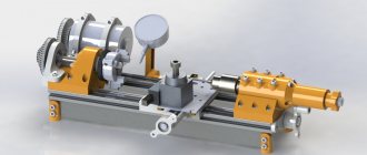
When all the necessary parts have been turned, it is necessary to assemble them into a single structure.
The parts of the future tabletop lathe are assembled on the assembly table.
It was decided to make the structure from flanges machined from round timber with a diameter of 120 mm. To make them easier, a central hole of Ø 55 mm is drilled in them. There are three holes Ø 20 mm.
Additional holes for threaded fasteners are drilled at the end. M6 screws can be used to secure the remaining parts in a given position.
A bronze bushing is pressed in for the future lead screw. Internal Ø 16 mm.
The bed guides are made of ductile cast iron. They have longitudinal grooves. The cylindrical part allows it to be fixed in the flange holes.
The guide is inserted so as to combine all the existing elements.
To maintain a given distance, spacer bushings are used. They are installed in the spacer between the flanges.
The second guide is made exactly the same as the first.
Having assembled the base for the headstock, proceed to assembling the rear one.
The frame is tightened with nuts. The foundation of the future bed has been created.
The machine will stand resting on the front supports. They are secured with screws to the flanges.
Support bushings move along the guides. The caliper and tailstock will be mounted on them. The long sleeve acts as a guide, and the short one acts as a support. The grooves on the rollers do not allow them to move.
Structurally, the support bushings are made of different lengths. This solution allows you to increase the working stroke.
The length of the processed parts can be sufficient so that the parts have dimensions up to 250 mm.
The caliper platform is secured with M6 screws.
The holes for the platform are drilled in place. This part is made individually. If you try to make it only according to the drawing, a jamming effect may appear.
By analogy, the tailstock platform is made. It is also drilled in place. It is necessary to ensure sliding movement along the guides.
It is necessary to ensure the rigidity of the frame. A special cylindrical half ring is machined for the headstock. It is bolted to the flanges.
The movement of tools on the support or tailstock is carried out by a lead screw. A rectangular thread with a slight slope (12.5 ⁰) is machined on it. When the lead screw rotates, the parts attached to it move forward or backward. Depends on the direction of rotation.
A hole with a pressed bushing was created for the lead screw.
To ensure that the screw rotates freely, but does not itself move along its axis, thrust bearings are used. They are placed in front and behind the rear support.
To prevent axial movement of the lead screw, a locking sleeve is installed. It is secured with an M6 bolt. Now the screw will not move along the axis, but it can rotate.
A vernier (a device with notches) is placed on top of the fixing sleeve. One turn of the screw moves the caliper or tailstock 10mm. Using the scale as a guide, precise displacements can be made in the longitudinal direction.
To rotate the lead screw, a handwheel is installed. The small handle allows you to easily rotate the flywheel.
Risk helps you navigate. Looking at it, the desired axial displacement is set.
The machine bed is assembled. Now you need to install the headstock. The part will be recorded in it.
Transverse movement guides are installed on the plates.
The headstock is mounted on top. The picture shows a pulley block, a three-jaw chuck and a central bushing.
The pulleys can be easily removed and installed on the spindle.
The spindle itself is installed inside the central bushing.
There are radial bearings between the spindle and the bushing. They allow free rotation.
The central bushing is bolted to the frame.
After installing the bearings, a spindle with a three-jaw chuck is mounted. A hole Ø 35 mm is machined inside the spindle. If necessary, workpieces of smaller diameter can pass through it.
The machine is ready. The drive is carried out through V-belts from an electric motor installed to the side.
Video: DIY mini lathe.
Safety precautions
Since we are talking about an electrical machine and working with metals, the requirements for compliance with safety regulations will be clear and strict, from which there is no escape. The first step is to check the functionality of the new machine immediately after its manufacture.
How to check the performance of the machine: the spindle should rotate without the slightest difficulty. It is necessary to measure the coincidence of the axis of rotation of the parts in the machine with the center of symmetry of the same part. The common axis should be visible at the front and rear centers.
Elements of the design of a lathe.
The electric motor is always covered with a special casing, which protects the motor from dirt and metal particles, as well as the machine operator himself. If your device is made from a drill, no casing is needed.
If you decide to equip your homemade lathe with a powerful motor, be sure to test on your home network to see if it is enough for your powerful motor. In general, it is better to adhere to established traditions and use old friends - electric motors from household appliances.
Making a homemade metal lathe with your own hands is an excellent and elegant solution from all points of view. Ease of execution, cost savings, efficient processing of parts - all this is about homemade lathes.
Dimensions and drawings
When determining the dimensions of the machine, first of all, we focus on the maximum length and diameter of the parts being processed. Let us recall that in industry, low-power turning equipment has the following boundary parameters:
- length - up to 1150 mm;
- width - up to 620 mm;
- the distance from the top surface of the bed to the spindle axis (axis height) is about 180 mm.
It is hardly worth exceeding these values on homemade equipment. We must not forget that with increasing size the danger of bending the geometry of the machine increases many times over. When choosing the size of the support and determining the extreme points of its movement, calculating the distance between centers and the limits of movement of the tool holder, it is best to focus on the drawings of home-made machines. Made by folk craftsmen, they have proven their performance in practice, so it would be stupid not to use proven solutions.
Tailstock Drawing of the support and tool holder Drawing of the bed Drawing of the headstock Homemade lathe. General view Drawing of the tailstock