The open circuit voltage of a welding inverter is the voltage between the positive and negative output contacts of the device in the absence of an arc. For a welding inverter in good condition, it should be within the limits specified in the manufacturer’s instructions. Typically this voltage is from 40 V to 90 V. This rating ensures easy ignition of the arc when welding metal. This also creates safety for the welder.
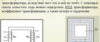
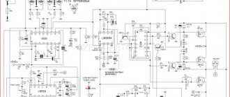
Scheme of an inverter semi-automatic welding machine.
What should be the open circuit voltage of a welding inverter?
The open circuit voltage of a welding inverter is the voltage between the positive and negative output contacts of the device in the absence of an arc. For a welding inverter in good condition, it should be within the limits specified in the manufacturer’s instructions. Typically this voltage is from 40 V to 90 V. This rating ensures easy ignition of the arc when welding metal. This also creates safety for the welder.
Scheme of an inverter semi-automatic welding machine.
Determining the characteristics
Choosing a price category is good, but you also need to select technical specifications. First, let's decide on the power supply. If you are choosing a unit for private use at home or in the country, most likely you will be more satisfied with power from a 220 V network. There are also welding inverters from 380 V, but it is unlikely that anyone has such sources at home. And if there is one, choose three-phase inverters. There are much fewer of them, but they also exist.
Welding current
How to choose a welding inverter based on technical characteristics? In this matter, they proceed from the products and their thickness that you plan to work with. First of all, select the maximum welding current that the unit can produce. It is designated Imax, the unit of measurement is Amperes.
There is a fairly clear relationship between the thickness of the metal you want to work with and the current that will be needed for welding. This dependence is presented in the table.
| Diameter of electrodes, mm | Metal thickness, mm | Welding current, Amps |
| 1.5 mm | 1.2 - 2.0 mm | 30 - 75 A |
| 2.0 mm | 1.5 - 3.0 mm | 40 - 100 A |
| 2.5 mm | 1.5 - 5.0 mm | 50 - 120 A |
| 3.0 mm | 2.0 - 12.0 mm | 100 - 150 A |
| 4.0 mm | 4.0 - 20, mm | 120 - 200 A |
| 5.0 mm | 10 - 40 mm | 170 - 270 A |
If you are going to weld ferrous metal (angles, channels, etc.) with a thickness of no more than 1 cm, it is enough for you that the inverter can produce 160-180 Amperes. If, at least from time to time, you have to work with greater thickness, you need a current of up to 200 Amps. Sheets of iron thicker than 2 cm are not used anywhere in everyday life, so 220-250 Amps for a home or cottage is clearly too much. It’s hardly worth overpaying for unnecessary power; then it’s better to spend the money on purchasing a unit of a higher class (or on a good chameleon mask, without which it will be difficult for a novice welder).
In addition to the welding inverter, you will also need protective gloves and a welder’s mask. For beginners in welding, a chameleon mask is recommended
The minimum current Imin is needed when welding thin metals with an inverter. If you need to weld steel or stainless steel up to 2 mm thick, you will need to heat the parts being welded as little as possible. This is where the minimum current is needed. As a rule, the lower limit of adjustment is 10 A, but there are units on which you cannot set it to less than 30-40 A. They are good for those cases if you have special equipment for “delicate” operations (for example, a semi-automatic welding machine).
The organization of current regulation is also important. It can be stepped or smooth. Continuous adjustment is better - it allows you to more accurately select the operating mode for each metal and electrode.
Open circuit voltage
This characteristic is measured with the equipment turned on and no load. Denoted as Uxx, the unit of measurement is Volts (V). It determines how easily the welding arc will be ignited and how stable the arc will be. The range of values is 40-90 V. The higher the declared open circuit voltage, the easier the welding will be.
Technical characteristics of the welding inverter Fubag in 160. Open circuit voltage can be described as follows
Supply voltage
As already mentioned, most inverters operate from a 220 V network. But on Russian networks, a more or less stable voltage is maintained only in large cities. In rural areas, a voltage of 190 V is already good. But the good thing about inverter welding machines is that they are undemanding in terms of supply voltage. They cook quietly at 180-190 V, and some models can “pull” an electrode with a 3 mm diameter even at 150 V.
If the voltage in your village is low, pay attention to this indicator. It is usually written simply as “voltage” and the minimum and maximum values are indicated through a dash: for example, 150-245 V. Sometimes you can see the following entry: 220 V +10%, -30%. This means that the device will cook normally if the supply voltage is in the range from 154 V to 244 V (220 V - 30% = 154 V, and 220 V + 10% = 244 V).
Maximum current operating mode
If you have to work at the maximum possible current, then the unit will have to be given time to cool down. That is, cook for a while, rest for a while. These intervals are counted for 10 minutes, designated in the technical data as “DC at maximum current”, measured as a percentage - %.
For example, if the characteristic specifies the PV at a maximum current of 40%, this means that out of 10 minutes you can cook 4, and 6 you will wait until the device cools down. At least 50-60% are considered normal characteristics, 70% and above are considered good.
Technical characteristics of inverter welding TORUS-165 MASTER (Torus 165 Master)
Please note that this requirement only applies to the maximum current, or close to it. At medium or low currents there is no need for forced stops. You will still have to change the electrodes or position or move the part from time to time. So there will be pauses.
That's all the technical parameters that are needed. Now you know how to choose a welding inverter based on its characteristics. But that's not all. There are also additional functions. For beginners they can be very useful. And some operational issues may also influence the choice.
Open circuit voltage: how it occurs and what it affects
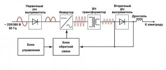
The open circuit voltage is obtained by converting the mains voltage (220 V or 380 V, 50 Hz) in two series converters, first into direct current voltage and then into alternating current with a frequency of 20-50 kHz. Then the high-frequency voltage is supplied to the regulator, which maintains the required voltage at the output terminals and the specified current when the arc is ignited.
Current conversion in a welding inverter.
Many people believe that this parameter only affects the ease of igniting the arc; the higher the voltage, the easier it is to ignite the arc. Working conditions for welders when installing structures are far from ideal. Accidentally touching live parts with excessive voltage may lead to an accident.
For many inverter models, the no-load voltage and operating current are directly related. When welding metal covered with a thick layer of rust or paint, the arc is difficult to ignite.
If in this situation the open-circuit voltage is increased, the operating current will be excessive, and instead of a high-quality metal connection, slag and pores may form.
Principle of operation
Inverter welding machine: what does it mean? A welding inverter is a converter of alternating current 220 volts to direct current 70-120 volts . An outdated welding rectifier does the same thing. The quality of the weld made using a transformer-rectifier strongly depends on the stability of the characteristics in the electrical network. The operation of the device itself can greatly influence the stability of the network parameters; when the arc is ignited, voltage surges begin.
What is inverter welding? The welding inverter also outputs 70-90 volts, but the conversion is carried out as follows.
- alternating current 220 volts 50 hertz is rectified and supplied to the input of the high-frequency generator;
- the generator creates a high-frequency (20-50 kilohertz) signal;
- it is fed to a transformer, which reduces the voltage to 70-90 volts;
- the current is rectified by the second rectifier and direct current is supplied to the electrode and the workpiece;
- the electric arc is ignited, the edges of the workpiece are melted, the electrode also melts, forming a cloud of protective gases and replenishing the weld pool;
- after cooling of the seam material, a permanent connection of high strength and durability is formed.
Now it becomes clear what inverter means: it is a converter with double inversion (from the Latin inversio, turning over, rearranging) voltage from alternating to direct and back.
Converting current at high frequencies made it possible to reduce the weight and dimensions of the transformer many times . Controlling the process at each stage using electronic circuits made it possible to ensure high stability of the output voltage, its independence from fluctuations in the supply network (within certain limits) and eliminated the negative impact of the inverter itself on jumps in the parameters of this network. In addition, welding inverters provide high stability of the arc, facilitate its ignition and prevent the electrode from sticking.
Welding rectifier device. The low-frequency transformer accounts for the bulky dimensions and heavy weight of the device. These are the main differences between an inverter and welding rectifiers. Semi-automatic welding machines are also built on the basis of an inverter current source, supplying welding wire to the working area instead of a rod electrode.
If the parameters of the electrical network are significantly lower than 180-190 volts, then a conventional inverter can no longer compensate for such a voltage drop. Often in remote areas it drops to 150 volts. In this case, inverters that can operate at reduced voltage come to the rescue. in their design there are two blocks designed to correct the situation:
- stabilizer with an extended range; it maintains the specified output voltage, despite fluctuations at the input;
- power factor corrector: an electronic circuit that adapts the operation of the entire device to changing power supply conditions.
These blocks do not perform miracles and do not violate the law of conservation of energy. If the input is below 135 volts, the welding machine will not work .
In addition, only the thinnest electrodes or wire can be used. The corrector will try to keep the power delivered to the arc at the same level.
[my_custom_ad_shortcode1]
What determines the correct selection of the mode?
A correctly set idle mode ensures high-quality combustion of the electrode and a clearly defined droplet transfer of metal into the weld pool, forming a reliable connection with weld root penetration. The formation of spatter when igniting and breaking the arc is minimal; the surface of the parts being welded in the weld area requires almost no additional cleaning. One of the main signs of a correctly selected mode is the characteristic hissing sound when the arc burns.
Three-phase welding rectifier with no-load voltage regulation by sectioning the turns of the transformer windings.
Some models of welding inverter have an additional protective function against electric shock to the welder at increased open circuit voltage. The device automatically reduces the voltage to a safe value when an emergency occurs and restores it when it disappears. Devices with increased open circuit voltage are used when welding with electrodes with refractory coating used to work with specific alloys.
Certain inverter models are equipped with a welding oscillator circuit for better arc ignition. Such devices were used on transformer welding machines with alternating and direct current. The oscillator converts the mains supply voltage into a voltage of 2.5-3 kV with a frequency of 150-300 kHz and outputs it to the output terminals in pulses lasting several tens of milliseconds. The oscillator consists of a step-up low-frequency transformer connected to an oscillating circuit and a spark gap with tungsten contacts. At the output there are capacitors that pass high-frequency currents and limit the low-frequency current from the welding machine.
Such devices also provide protection against electric shock. The power consumption of the oscillators is 250-300 W, which slightly increases the total power consumption of the welding inverter. Oscillators can be purchased as a separate unit or made independently.
What does the EMF in the windings of a transformer depend on?
Scientific Research Enterprise of General Mechanical Engineering, JSC
In the previous article, I indicated that the instantaneous value of the EMF in the transformer winding is determined by the number of turns ω of the wire in it and the rate of change of the magnetic flux dΦ/dt
where ω is the number of turns of the transformer winding,
dFV/dt – rate of change of magnetic flux.
However, in most cases, we are not interested in the instantaneous value of the emf, but in the effective one. Therefore, we derive an expression that determines the effective value of the EMF in the windings of the transformer. This can be done analytically by integrating the function of change in magnetic flux dΦ/dt, or by finding the average value of the emf Ecp and the shape factor of the emf kf. I will output the expression using the second method.
The magnetic flux flowing in the transformer core changes in accordance with a certain periodic function and has two amplitude values: maximum +Фm and minimum –Фm, then the total change in magnetic flux over half-cycle T/2 will be
Then the average value of the EMF Еср in the transformer winding will have the form
where ω is the number of turns of the transformer winding,
T/2 – half-period of change in the magnetic flux function,
f – frequency of magnetic flux change,
Фm is the amplitude of the magnetic flux.
The effective value of the EMF and its average value are related by the shape coefficient of the EMF curve kf, then the effective value of the EMF in the transformer winding will be determined by the following expression
where kf is the EMF shape coefficient,
f – frequency of EMF change,
ω – number of turns of the transformer winding,
B – magnetic induction in the core,
Sc is the cross-sectional area of the transformer core.
Let us give examples of the effective value of the EMF for sinusoidal, rectangular (meander) and triangular changes
From the above it follows that, provided that the electromagnetic induction B is constant, the EMF is proportional to the design parameters of the transformer, the cross-section of the magnetic circuit Sc and the number of turns ω. The correct choice of the value of electromagnetic induction B is one of the key tasks when designing a transformer. In addition, with increasing frequency f, the EMF increases, therefore, to realize the same EMF with increasing frequency, smaller dimensions and weight of the transformer are required. This factor is the main advantage of high-frequency transformers, which are most often used nowadays.
Possible malfunctions and their causes
The causes of problems with the inverter may arise due to:
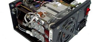
Functionality of the welding inverter.
Thermal deformation and voltage at the output of the device are inextricably linked. Due to voltage surges, the temperature of the arc changes, the metal either does not warm up to the required temperature, or burns out, forming slag and pores. Troubleshooting methods depend on the problem found. The simplest reason may be poor contact in the connections of the welding cables with alligator clips and plugs for connecting to the inverter. It leads to the appearance of deformations during welding. Typically, such a defect manifests itself in sharp non-periodic jumps in the welding current, spontaneous attenuation of the arc, which can lead to poor-quality connections, deformation and stress when welding parts from uneven heating.
The solution is simple and can be done independently. To eliminate it, you need to remove the protective insulating handles, disconnect the cable and inspect the connection points. If there are oxides and traces of heating, the surfaces must be cleaned with emery cloth and assembled, carefully tightening the connecting bolts. Cables with broken or broken wires and damaged insulation must be replaced with similar ones. It is better to keep the cable length the same. Many inverter models are designed for a strictly defined inductive reactance load and can change the operating parameters when the cable length changes.
The next reason may be a malfunction of the device itself. To determine the operability of the device, it is necessary to measure the voltage at the output terminals of the inverter and the voltage in the supply network with the device. At normal mains voltage, a low voltage at the inverter output will indicate a malfunction of the device. It is better to entrust inverter repair to specialists from the service center.
If the voltage at the inverter output is within acceptable limits at normal supply voltage, you should carefully check the supply voltage supply circuit to the device from the power supply input point or meter. The minimum power consumption of devices in welding mode is within 4-5 kW. The required cross-section of copper supply wires for such power must be at least 2.5 mm 2 with a long-term permissible operating current of 25 A throughout the entire power circuit. A cable with a smaller cross-section will heat up quickly and the voltage loss on it will increase.
It is imperative to check the quality of all connections along the power supply circuit. Weak twisting or other types of poor-quality connections can also create problems during welding work and lead to fire. Detachable connections from a plug-socket pair must be of a new type with an increased diameter of electrically conductive pins on the plugs. Old type forks cannot withstand the load under long-term operating conditions. Sockets must also be of the appropriate type. The length of the power supply lines cannot be more than 50 m, unless otherwise specified in the technical documentation for the device.
In rural areas, abnormal operation of inverters is often observed due to overloaded common power lines and low network voltage.
If, when trying to ignite an arc, the supply voltage drops to an unacceptably low value at the input point, this indicates insufficient capacity of the common line and its overload.
Sometimes voltage stabilizers can help in such a situation. The effectiveness of stabilizers also depends on several reasons and is not always justified. The total power consumption of the kit from the power supply network will be the power of the welding device plus losses in the stabilization device. Electricity costs will increase, overload of common lines will increase, which will further reduce the input voltage.
Before deciding to use such a device in conjunction with welding equipment, it is advisable to contact the electrical network with a written statement about poor-quality power supply.
Source
Ensuring efficiency
The instability of power network parameters is caused by the uneven distribution of electricity consumers between phases . In old-style networks there is no possibility of automatic phase-to-phase load balancing. The second reason is severe wear and tear of switching and distribution network equipment, poor insulation condition, and insufficient cable cross-section. All together these factors lead to the fact that, with a standard value of 220 volts, what is actually measured fluctuates between 140 and 270.
And this situation is typical and familiar for most rural areas, remote from regional centers and major highways. To cope with network voltage instability and ensure efficient operation of the welding machine, use the following techniques:
- connection through a powerful voltage stabilizer, the power reserve must be at least 40% of the rated value for the inverter;
- use of an inverter-type welding machine with a KKM power correction function;
- inclusion in the circuit of an oscillator that generates high-frequency pulses and facilitates ignition and maintenance of the electric arc;
- selection of welding materials and welding modes to achieve high quality welds.
A powerful stabilizer is bulky and heavy, its price is approximately 1-2 thousand rubles per kilowatt of power. If the stabilizing unit is built into the welding machine itself, this can significantly reduce costs .
The power coefficient correction function also allows you to improve arc stability and seam quality, avoid electrode sticking and burn-through, and also consume slightly less electricity.
[my_custom_ad_shortcode3]
DOMOSTROYPlumbing and construction
You can test the welding inverter to see what it is capable of. We take the most affordable TIG welding inverter. I will give an example of a device in the photo there IN 256T/ IN 316T.
If you look at the table, it shows where the idle speed is located in the form of an indication. On such devices, the idle speed is programmed by a computer. When you select the desired mode, the idle current is automatically set. It can be checked with a regular voltmeter at the ends of the power wires in the on state. That is, on the holder and the crocodile. The voltage drop should not deviate by more than five volts when igniting the arc and welding.
For example, if you ate a Chinese state employee, you will not find information about idle speed at all. Plus the Amperes are too high. In fact, some won’t even handle Uoni 13/55 electrodes. And why all? This electrode requires an idle current of 70 volts at 80 amps. And such welding machines are designed in such a way that as the current increases, the voltage also increases. In other words, at the highest current they will give you 90 volts. The voltage even before the secondary winding is controlled by a unit that converts the high voltage into the primary winding. Then, under the influence of electromagnetic force, it is transmitted to the secondary winding. The tension removed from her passes on. If the voltage at the input of the primary winding is low, then the output will be low.
Let's consider the primitive VD-306M U3. At low currents of 70-190 A, the voltage is 95 volts plus or minus 3 volts. At high currents of 135-325 A, the idle current is 65 volts plus or minus 3 volts. Moreover, it is stable in all current ranges. No matter how you twist the crank and change the amps to your heart's content, the idle speed will not decrease.
What am I getting at if the welding inverter does not weld well at low currents, the reason is in the control unit described above. As some say, install an additional choke or a ballast at the output. We turn the current up to full and adjust it at the ballast. The extra amperes will be taken over and the idle speed will remain unchanged.
Just for fun, check your welding machine. Throw the probes from the voltmeter onto the power cables and try to cook. See how the voltage drops. I myself personally cooked on a home network with an Interskol 250A inverter using 3mm UONI 13/45 electrodes with reverse polarity. As soon as I didn’t twist the amps properly and couldn’t ignite them, but the MP-3s burned, be healthy from the first touch.
When purchasing equipment, read in the passport how much idle current the device produces and at what currents. If this is not professional equipment, you will not be able to adjust the idle speed in any way. If not the method described above. You are unlikely to find such information on the unit body itself. Manufacturers usually hide it with big names and current strength.
Question:
Answer:
Among the characteristics of welding inverters there are several important indicators. This is the supply voltage (220 or 380 Volts), the range of output current (from 10 to 600 Amperes), available functions, weight and dimensions of the device, as well as no-load voltage.
This characteristic shows us at what voltage the current reaches the electrode after it has gone through all the stages of conversion after the power supply. Let us recall that current flows from the electrical network through the power cable to the first converter, from there it comes out constant and goes to the filter, and then to the second converter. As a result, we again get alternating current with a frequency of not 50 Hz, but 20-50 kHz. This is followed by a decrease in input voltage with a simultaneous increase in current. As a result, we get an output voltage of 55-90 Volts and a force that can be adjusted within the range specified for each specific model.
This output voltage is the open circuit voltage. Two points depend on it: • The safety of the tool for the owner; • Ease of igniting the welding arc.
The higher the open circuit voltage, the easier it will be to ignite the inverter's welding arc. It would seem that it would be worthwhile then to buy inverter devices with a high no-load voltage. But high voltage is quite dangerous for a person in case of contact, so it is not always made high. If you still want to light the arc easily, then you should choose a welding inverter with a high voltage, but with an additional installed protection function that automatically reduces the voltage to a level safe for humans if there is a risk to the user, and then returns the level back.
If you have not yet chosen a welding inverter, then among household models, pay attention to Aurora welding machines and Blueweld inverters; for semi-professional models, we can recommend Foxweld welding machines and Svarog MMA equipment; for “professionals,” Kemppi welding machines and EWM MMA inverters are good. This equipment is available on our website in the catalog and can be purchased with delivery to any corner of Russia.
When coming to a store or looking at online portals, the buyer first of all looks at the price tag of the equipment presented, naturally looking for an option that would be optimal in terms of cost and quality ratio.
At the same time, price is not always an objective selection criterion. It is in the lowest price category that there is a huge layer of low-quality goods. In this article we will talk about technologies that are used to deceive buyers.
Let's start with the simplest:
Overestimation of current characteristics
Often the numbers indicated on devices, in instructions or on equipment boxes have nothing to do with reality. It happens that the promised and actual values of the welding current differ by 20 or even 50%. For example, instead of the declared 200A, the device produces only 125.
When choosing a welding machine, the buyer looks at the upper limit of the welding current and compares the price with competitors based on their technical characteristics. As you understand, the cost of 120 and 200A devices differs significantly in favor of the first, and you are offered to pay for it as for a much more powerful device.
A professional never buys a welding machine with the current characteristics that he needs, i.e. If a welding specialist needs a 180A current source, then in the store he will opt for a 200 - 250A inverter. This choice, on the one hand, protects the buyer from underestimating the characteristics, on the other hand, allows you to have a reserve of power.
The manufacturer, knowing about this feature of the choice, periodically overestimates the current characteristics. As a result, the power reserve that the buyer expects to receive turns out to be zero, but the allegedly “200A” device costs a little more than the 180A analogue.
Another trick of marketers is to assign a name to a device with a digital code, which hints at the welding current, but has nothing to do with it. Let's take, for example, the imaginary device “Oak 250” (I hope there is no such thing), or even “Oak 250A” - the name seems to hint to us that the device should have a current of 250 A, while in the instructions for the inverter it is indicated 160A, but who reads these pieces of paper? So, less attention to the inscriptions on the case - more time studying the devices.
When making leapfrogs with characteristics, sellers rely on the buyer’s superficial knowledge. The average welding enthusiast will not be able to check the characteristics of the tool he plans to purchase.
Unfortunately, our people trust advertising or “digital displays” more, which often have nothing to do with real current. Here is clear proof: in one of our videos dedicated to comparing welding machines, we tested the ELAND inverter:
When connecting the device to a static load stand, it turned out that the readings of the ammeter on our device and the ELAND digital display differ by 50A (!). Many manufacturers install on their equipment not measuring instruments, but indicators that show values depending on the position of the adjustment knob. Those. the numbers on the display are not ammeter readings - they are just numbers.
Additional functions
The reason for deception may be additional functions of the device. Antistick, Hot Start, Arc Force
VRD
voltage reduction function - they have become a gentleman’s set, which is featured on almost all modern inverters. Sellers fear that the absence of any of these functions may alienate the buyer, and therefore write that the inverter is equipped with a full range of options, regardless of whether they are present on the device or not.
In turn, many buyers do not really understand what, for example, Hot Start is, or what is hidden behind the abbreviation VRD. Our little educational program on the links. Click - don't hesitate:
The most common type of deception, as you understand, is the absence of declared functions on the inverter.
Their presence, in addition to Antistik and VRD, can only be checked in a laboratory. Anti-sticking is checked by prolonged contact of the electrode and the part being welded. If this function is present, the electrode should not become red-hot: after a short heating period, the device, with the Anti-Stick function, should reset the welding current to a minimum and keep the electrode suitable for further work.
The presence of VRD is checked with a voltmeter connected to the device bayonets. The no-load voltage value when VRD is turned on should not exceed parameters that are safe for the welder: 12-18-24 Volts, depending on the values declared by the manufacturer. The presence of VRD is checked with a voltmeter connected to the device mounts.
There is an even simpler method of checking, proposed by one of the owners of the AURORA MINIONE 1600. However, we do not recommend using it if you are not sure whether this function is available on the device.
?t=5m58s
Open circuit voltage
Since we are talking about safety, we cannot ignore such a parameter of welding equipment as open circuit voltage. This is a “double-edged sword”, on the one hand, the higher the voltage, the more reliable the ignition will be, the higher the elasticity of the arc, and the more stable the welding process itself. On the other hand, high open circuit voltage is limited by welder safety requirements. As a result, the minimum open circuit voltage for coated electrode welding power sources is considered to be 40 V, and the maximum value should not exceed 100 V (average value). You can check the voltage, as in the case of VRD, with a voltmeter connected to the output terminals of the welding source.
The most common deception is overestimating the idle value. Instead of 80-90 V, the device produces only 40, which cannot but affect the ignition and stability of the arc.
Source
Aurora PRO Inter 200
This new product stands out for the capabilities of its stabilizer and PFC unit. The test confirmed the ability to cook effectively even from 140 volts. In this case, the operating current develops from 20 to 200 amperes. Supports work with a 100-meter extension cord if the wire cross-section is 2.5 mm or more. Can work continuously up to 60% of the total time.
All of the listed models are compact and modest in weight, not exceeding 8 kg . Of course, when working at the lower limit of the supply voltage, you should not rely on the maximum welding current and 5 mm electrodes.
But 1.6 and 2 mm will cook stably, without sticking and annoying burns of thin workpieces and small parts. During prolonged operation, wear and tear on the parts and components of the device's power supply will increase.
It is also important to consider the reputation of the manufacturer . Little-known companies that have recently appeared on the market often offer their products at a low price compared to well-known brands. At the same time, they promise miracles that contradict the law of conservation of energy, for example, operation at an input voltage of 90 volts. This can only mean one thing: a clear example of false advertising. In this case, the input voltage will be close to the output voltage, and no matter how much it is converted, it will not be possible to maintain the required current parameters.
[my_custom_ad_shortcode2]
How to check the open circuit voltage of a welding inverter
One of the most used electrical devices is the transformer. This equipment is used to change the magnitude of electrical voltage. Let's consider the features of the transformer no-load mode, taking into account the rules for determining characteristics for various types of devices.
The transformer consists of primary and secondary windings located on the core. When voltage is applied to the input coil, a magnetic field is formed, inducing a current in the output winding. The difference in characteristics is achieved due to the different number of turns in the input and output coils.
Transformer operating principle
Transformer no-load mode
Idle circuit (XX) is the connection of a device when the rated alternating voltage is supplied to the primary winding, and the circuits of all secondary windings are open (no loads are connected).
In a voltage converter, the division of windings (coils) into primary and secondary is conditional. Any of them becomes primary when the original alternating voltage is applied to it. Others, in which EMF is induced, become, accordingly, secondary.
The idle test is carried out according to the scheme shown in the figure.
Consequently, any transformer, depending on the connection method, can be either a step-down or step-up transformer (except for an isolation transformer - with a transformation ratio equal to unity).
Since the secondary coil circuit is disconnected, there is no current in it (I2 = 0). I1 flows in the primary, forming the flux of the magnetic induction vector F1 in the magnetic circuit. The latter changes according to a sinusoidal law, but due to the magnetization reversal of the steel, it lags in phase from I1 by angle B (loss angle).
The following terminology applies:
- I1: transformer current XX;
- F1: working magnetic flux.
Under the influence of F1, an EMF arises in all coils:
- in primary – self-induction (E1);
- in secondary ones – mutual induction (E2).
The dependence of EMF on various parameters is determined by the formulas:
E1 = 4.44 * f * W1 * Ф1max *10-8,
E2 = 4.44 * f * W2 * Ф1max * 10-8, where
F—frequency, Hz;
W1 and W2 - number of turns in the windings;
Ф1max is the magnitude of the magnetic flux at the maximum point.
Consequently, the numerical value of the EMF is directly dependent on the number of turns of the coil. From the ratio of the EMF in the primary and secondary windings, the main parameter of the device is determined - the transformation ratio (K): K = E1 / E2 = W1 / W2.
Compared to the primary coil, the secondary coil contains:
- in a step-up transformer – more (K is less than one);
- in the downward direction it is less (K is greater than one).
In addition to the working (main) magnetic flux Fr1 is formed in the installation. These are power lines that branch off from the working magnetic flux F1 in the core and close through the air around the turns of the coils. Like F1, Fr1 is variable, which means that, according to the law of electromagnetic induction, it induces self-inductive emf Ep1 in the primary winding.
E1 and Ep1 are always directed opposite the voltage U1 applied to the primary winding. By the nature of their effect on current, they are similar to a resistor, which is why they are designated by the term “inductive reactance” (X).
Capacitive and inductive reactance
Consequently, creating I1, the voltage U1 overcomes the active resistance R1 of the primary coil and both self-induction emfs. Mathematically it looks like this: U1 = I1 * R1 + (-E1) + (-Ep1).
The recording is made in vector form, therefore, the symbols “-” are placed before the designations of the self-induction EMF: they indicate the opposite direction of these vectors relative to the voltage U1. The no-load current I1 is not strictly sinusoidal.
It is distorted because it contains the so-called third harmonic component (THC), caused by eddy currents, hysteresis and magnetic saturation of the magnetic circuit. But with a certain degree of approximation, suitable for practical calculations, it can be replaced by an equivalent sinusoidal current with an equivalent effective value.
Stages of commissioning tests ↑
Primary performance testing is carried out in several directions at once. Mandatory ones include:
In this case, the sequence of performing all types of the above tests plays an important role.
Engineering has all the necessary tools for high-quality diagnostics of transformers, a well-coordinated team of professionals and licenses that give the right to carry out all the necessary tests and measurements. By choosing the ProfEnergia electrical laboratory, you are choosing reliable and high-quality operation of your equipment!
Transformer no-load mode
Idle circuit (XX) is the connection of a device when the rated alternating voltage is supplied to the primary winding, and the circuits of all secondary windings are open (no loads are connected).
In a voltage converter, the division of windings (coils) into primary and secondary is conditional. Any of them becomes primary when the original alternating voltage is applied to it. Others, in which EMF is induced, become, accordingly, secondary.
The idle test is carried out according to the scheme shown in the figure.
Consequently, any transformer, depending on the connection method, can be either a step-down or step-up transformer (except for an isolation transformer - with a transformation ratio equal to unity).
Since the secondary coil circuit is disconnected, there is no current in it (I2 = 0). I1 flows in the primary, forming the flux of the magnetic induction vector F1 in the magnetic circuit. The latter changes according to a sinusoidal law, but due to the magnetization reversal of the steel, it lags in phase from I1 by angle B (loss angle).
The following terminology applies:
- I1: transformer current XX;
- F1: working magnetic flux.
Under the influence of F1, an EMF arises in all coils:
- in primary – self-induction (E1);
- in secondary ones – mutual induction (E2).
The dependence of EMF on various parameters is determined by the formulas:
E1 = 4.44 * f * W1 * Ф1max *10 -8,
E2 = 4.44 * f * W2 * Ф1max * 10 -8, where
W1 and W2 - number of turns in the windings;
Ф1max is the magnitude of the magnetic flux at the maximum point.
Consequently, the numerical value of the EMF is directly dependent on the number of turns of the coil. From the ratio of the EMF in the primary and secondary windings, the main parameter of the device is determined - the transformation ratio (K): K = E1 / E2 = W1 / W2.
Compared to the primary coil, the secondary coil contains:
- in a step-up transformer – more (K is less than one);
- in the downward direction it is less (K is greater than one).
In addition to the working (main) magnetic flux Fr1 is formed in the installation. These are power lines that branch off from the working magnetic flux F1 in the core and close through the air around the turns of the coils. Like F1, Fr1 is variable, which means that, according to the law of electromagnetic induction, it induces self-inductive emf Ep1 in the primary winding.
E1 and Ep1 are always directed opposite the voltage U1 applied to the primary winding. By the nature of their effect on current, they are similar to a resistor, which is why they are designated by the term “inductive reactance” (X).
Capacitive and inductive reactance
Consequently, creating I1, the voltage U1 overcomes the active resistance R1 of the primary coil and both self-induction emfs. Mathematically it looks like this: U1 = I1 * R1 + (-E1) + (-Ep1).
The recording is made in vector form, therefore, the symbols “-” are placed before the designations of the self-induction EMF: they indicate the opposite direction of these vectors relative to the voltage U1. The no-load current I1 is not strictly sinusoidal.
It is distorted because it contains the so-called third harmonic component (THC), caused by eddy currents, hysteresis and magnetic saturation of the magnetic circuit. But with a certain degree of approximation, suitable for practical calculations, it can be replaced by an equivalent sinusoidal current with an equivalent effective value.
Open circuit voltage: how it occurs and what it affects
The open circuit voltage is obtained by converting the mains voltage (220 V or 380 V, 50 Hz) in two series converters, first into direct current voltage and then into alternating current with a frequency of 20-50 kHz. Then the high-frequency voltage is supplied to the regulator, which maintains the required voltage at the output terminals and the specified current when the arc is ignited.
Current conversion in a welding inverter.
Many people believe that this parameter only affects the ease of igniting the arc; the higher the voltage, the easier it is to ignite the arc. Working conditions for welders when installing structures are far from ideal. Accidentally touching live parts with excessive voltage may lead to an accident.
For many inverter models, the no-load voltage and operating current are directly related. When welding metal covered with a thick layer of rust or paint, the arc is difficult to ignite.
If in this situation the open-circuit voltage is increased, the operating current will be excessive, and instead of a high-quality metal connection, slag and pores may form.
Advantages and disadvantages
The main advantages of such devices are as follows:
- the ability to reduce the supply voltage to 135 volts;
- ensuring stable arc power during large amplitude throws;
- compensation of losses when connecting through long extension cords.
There are also disadvantages:
- at reduced voltage you have to work on thinner electrodes or wire;
- the thickness of the workpieces to be welded is also limited;
- the cost of such a device is a quarter higher than a regular one (with equal power and general functionality).
If we compare the main advantages and disadvantages inherent in low-voltage inverter welding machines, the scope of their application becomes obvious. This:
- remote areas with low quality power supply;
- the need to operate from a household electric generator;
- connection via extension cords from 50 meters.
The devices will allow you to make seams of good quality even in such difficult conditions.
[my_custom_ad_shortcode2]
Loss table
When the second coil circuit is open, it does not use any operating power. The power that the first one consumes has a certain active percentage (this represents the losses of the device), but the reactive one, responsible for magnetization and given to the generator, dominates. As for the lost power, most of it is spent on magnetization reversal processes and the generation of magnetic circuit current eddies. Because of this, the latter begins to overheat. Since the leakage flux does not depend on the load electric current, there are power losses not only at idle, but also when applying loads. Another part of the losses (very small) is spent on heating the coil wire. Its low value is due to the wiring resistance and no-load current.
At a voltage of 10/0.4 kV, the amount of losses will increase as the power increases. For a rated power of 250 kVA, the losses will be 730 W, for 400 kVA - 1000 W, for 2500 kVA - 4200 W. After years of operation, processes occur in the magnetic circuit that increase the amount of losses: the insulation wears out, the structural characteristics of the metal change. Because of this, up to 50% of power can be lost.
Idling of three-phase device
The nature of the operation of the 3-phase device in XX mode depends on the magnetic system and the winding connection diagram:
- primary coil - “triangle”;
- secondary - “star” (D/Y): there is a free circuit of the TGC current I1 through the windings of the device. Therefore, the magnetic flux and EMF are sinusoidal and the unwanted processes described above do not occur; Y/D circuit: TGS magnetic flux appears, but the current from the additional EMF induced by it flows freely through the secondary coils closed in a “triangle”.
This current creates its own magnetic induction vector flow, which extinguishes the third GS of the main MP that causes it.
As a result, the magnetic flux and emf have an almost sinusoidal shape, the primary and secondary coils are connected in a star (Y/Y). In the last TGS circuit, there is no current I1, since there is no path for it: the third harmonics of each phase at any time are directed towards the zero point or away from it. Because of this, the magnetic flux is distorted.
Further is determined by the magnetic system: A three-phase transformer in the form of a group of one-phase ones: the TGS of the magnetic flux is closed in each phase along its own core and, due to the low magnetic resistance of the latter, reaches an amplitude of 15% - 20% of the working magnetic flux.
It creates an additional EMF, the amplitude of which can already reach 45% - 60% of the main EMF. Such an increase in voltage can lead to insulation breakdown with subsequent breakdown of electrical installations. Transformers with an armored rod magnetic system have the same phenomena (the third harmonic magnetic flux is closed along the side yokes of the magnetic conductor).
Three-rod magnetic system: the TGS has no path along the magnetic core and is closed through a medium with low magnetic permeability - air, oil, tank walls. Therefore, it has a small value and does not induce significant additional EMF.
What determines the correct selection of the mode?
A correctly set idle mode ensures high-quality combustion of the electrode and a clearly defined droplet transfer of metal into the weld pool, forming a reliable connection with weld root penetration. The formation of spatter when igniting and breaking the arc is minimal; the surface of the parts being welded in the weld area requires almost no additional cleaning. One of the main signs of a correctly selected mode is the characteristic hissing sound when the arc burns.
Three-phase welding rectifier with no-load voltage regulation by sectioning the turns of the transformer windings.
Some models of welding inverter have an additional protective function against electric shock to the welder at increased open circuit voltage. The device automatically reduces the voltage to a safe value when an emergency occurs and restores it when it disappears. Devices with increased open circuit voltage are used when welding with electrodes with refractory coating used to work with specific alloys.
Certain inverter models are equipped with a welding oscillator circuit for better arc ignition. Such devices were used on transformer welding machines with alternating and direct current. The oscillator converts the mains supply voltage into a voltage of 2.5-3 kV with a frequency of 150-300 kHz and outputs it to the output terminals in pulses lasting several tens of milliseconds. The oscillator consists of a step-up low-frequency transformer connected to an oscillating circuit and a spark gap with tungsten contacts. At the output there are capacitors that pass high-frequency currents and limit the low-frequency current from the welding machine.
Such devices also provide protection against electric shock. The power consumption of the oscillators is 250-300 W, which slightly increases the total power consumption of the welding inverter. Oscillators can be purchased as a separate unit or made independently.
Shutdown - current - no-load - transformer
| Charging currents and powers and average lengths of lines between reference substations. |
Switching off the no-load current of transformers is possible when cos f0 1 is inductive.
The built-in disconnector allows switching off the no-load current of the substation transformer.
Vertical installation disconnectors should not be used to disconnect the no-load current of transformers 110, as well as 35 kV with a power of 1,000 kVA and above.
If there is a fuse, turning on and off the no-load current of the transformer is carried out by a disconnector, and gas protection acts on the signal. They are usually installed together with load switches of the VNP type. In this case, the transformer is switched off and on using a load switch, and fuses perform the functions of current protection. In case of internal turn faults, the currents passing through the fuse are usually insufficient to trip it. The load switch is capable of switching such currents. Therefore, if there is gas protection on the transformer that is triggered by turn faults, it is advisable to carry it out with the effect not on the signal, but on disconnecting the load switch.
Conventional disconnectors are widely used to disconnect no-load currents of transformers, capacitive charging currents of lines, small load currents, etc.
| AC cutoff at i - o.| Equivalent circuit when switching off a small inductive current. |
According to Young, when switching off the no-load currents of transformers, the value of which does not exceed 10 A (actual. The issue of cutting small currents is usually associated with inductive circuits, since current cutting in these cases leads to significant overvoltages due to the release of a significant amount of energy stored in inductances (windings of transformers, reactors, etc.
In practice, this case occurs when turning off the no-load current of a transformer or turning off a transformer carrying a small inductive load.
Disconnectors can also be used to switch on and off the no-load current of transformers.
Disconnectors can, as an exception, be used to switch on and off the no-load currents of transformers with a power of up to 320 kVA at a voltage of up to 10 kW, charging currents of overhead power lines with a voltage of up to 35 kV and a length of no more than 10 km, as well as cable lines with a voltage of up to 10 kV and no more than 5 km long.
| Diagram of a radial network with substations on branches. |
In this case, after removing the load from the transformer, the latter is turned off by a disconnector / (turning off the no-load current of the transformer) or a switch on the side of the supply end of the line.
| Schemes using disconnectors as operational devices. |
Their operation in this case is fundamentally different from operation in a de-energized state and when the no-load current of the transformer is turned off.
Equivalent circuit in transformer mode
Direct electrical calculation of a transformer is complicated because it consists of two electrical circuits connected by a magnetic circuit.
To simplify calculations, it is more convenient to use a simplified equivalent circuit. In the equivalent circuit, instead of windings, complex resistances are used:
Each complex resistance consists of a series-connected active resistance and inductance.
Active resistance is the resistance of the winding wires.
The principle of operation of a transformer in idle mode
When a sinusoidal voltage is applied to the winding of the device, a weak current appears in it, usually not exceeding 0.05-0.1 of the rated value (this is the no-load current). It is created by a winding magnetomotive force; it is because of its action that a leading magnetic flux (denoted F) and a scattering flux F1, closed around the winding body, arise in a closed magnetic conductor element. The value of the magnetomotive force is equal to the product of the no-load current and the number of winding turns.
How to calculate electrical energy consumption
The leading flow creates two electromotive forces in the device: self-induction in the first winding and mutual induction in the second. F1 produces a leakage emf at the first coil. It has a very small value, because the flow that creates it is closed, for the most part, through air masses, the leading flow F is through the magnetic circuit. Since the main flow has a much larger scale, the electromotive force it generates for the primary coil is also much larger.
Important! Since the supplied voltage has the form of a sinusoid, the main flow and the winding electromotive forces it creates have the same characteristics. But due to magnetic saturation, the flux present in the device is disproportionate to the electric current creating magnetization, so the latter will not be sinusoidal
It is practiced to replace its real curve with a corresponding sinusoid with the same value. Current distortion is associated with the third harmonic component (a value determined by eddy flows and magnetic saturation).
Raising a faulty welding inverter
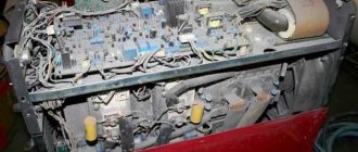
Another corpse came to me for repairs, Blueweld prestige 164. It’s brand new, even the smell has not yet dissipated. There is a bad reputation for it on the forums, there is a widespread defection of TGR. So. Let's start the repair. For now, look at the outside and what's inside. Photos taken from the internet. I didn’t take much pictures of the device itself.
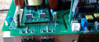
First you need to understand the symptoms. We connect the welding to the testing stand. I have a light bulb, an isolation transformer, a foot button for safety and a socket. All this stuff galvanically decouples the welder from the network and prevents short-circuit current if the welding goes into a short circuit. We hooked it up, press the button. And we see that our welder completely short-circuits all the mains voltage. Okay, let's open it up and take a look. The first step is to eliminate the short circuit. And that's why we unsolder the IGBT. They unsoldered it, checked the transistors, and it turns out they were also broken. The outputs are called briefly. Well. We hope that the short circuit has gone away and connect it to the socket. And again, the light bulb burns at full intensity. The short circuit did not go away. We call the entire power circuit again. And we find a broken diode BRIDGE. Unsolder. And voila, the short circuit is gone. Checking the resistance of the power lines after the bridge did not reveal a short circuit. So. The banal short circuit has been eliminated. Now you need to power the control room and look at the gate pulses from the IGBT transistors with an oscilloscope. The duty here is done in a cunning way. It is powered not like conventional welders, a separate switching power supply for the control board, but is powered from a power transformer. A tricky solution for sure. And convenient in terms of diagnostics. Right now I’ll just apply voltage to the power line of the duty room and take oscillograms. We submit, we throw the probe onto the gate and the ground onto the outermost terminal of the IGBT. I took the oscillogram from the forum, and the point is clear.
The signal was distorted, and the welder's IGBTs went out. And the signal is distorted due to a malfunction of the TGR. We wind up a new Galvanic Isolation Transformer. I was using a common mode filter ring. I wound 20 turns. And let’s see what happened to the signal.
Here he is. Normal meander. Don't worry about the splashes. There is no capacitive load on the gates. The IGBTs are faulty, the resistors were soldered at 220 ohms and the surges are not absorbed. We solder the IGBT transistors and replace the burnt bridge with a new one. And we supply mains voltage. So, the welding has started, the light bulb barely gets hot, the idle current consumption means minimal, great, let’s see if the voltage appears at the output, let’s see. and there it’s 60V, NOT OK AT ALL. We legally attach the newly made TGR to the board. Since the ring together with its leads cannot be firmly installed on the board, it was decided to fill it with epoxy. We body the mixture. As it turned out, the needle was not needed. Both the epoxy and the hardener turned out to be terribly viscous.
We wait a day and begin to clean the board from glue and molds.
Next comes assembly into the housing and testing on the electrode. The IGBTs were, to be honest, of dubious quality. I took it from Ali. But as it turned out, welding also works properly on such IGBT transistors. We burned a couple of electrodes at 100A. Everything works fine. PS These welding inverters, as I already said, are experiencing widespread defects in TGR. For some, the TGR core deteriorates over time; for others, due to harsh operating conditions (stupidly overheated). And why all? Because the core material is crap. If something goes wrong, the inductance immediately drops and the welding emits white smoke. Therefore, if you have such a device, then BE SURE TO CHANGE THIS TGR IN IT (pink square)
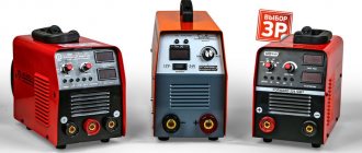
How to choose a welding inverter manufacturer
Now you know how to choose a welding inverter based on technical characteristics. The most difficult task remains: choosing the brand of the device, or rather, the manufacturer.
Chinese welding machines or?
In the category of household welding inverters, almost all units come from China. There are brands that are completely unknown to anyone, and there are brands that have been working for years and have earned a certain authority. Well-known Chinese brands are, as a rule, equipment produced by reputable factories equipped with modern equipment.
The “owners” of the brand are Europeans, Americans and even Russians, and production facilities are located in China. This scheme has long been worked out and is well known. That’s why recently even two lines have appeared in the descriptions of devices: “homeland of the brand” and “country of manufacture.” To call these inverters “Chinese” is not entirely correct, but they were manufactured there. In general, it's up to you.
Chinese inverter welding machines known on the market do not have the lowest prices. But they have been tested, and most of them have a network of service workshops or a repair contract with one of the similar services. Here are a few brands that have mostly good reviews:
- Welding inverters Resanta. The homeland of the brand is Latvia, the manufacturer is China. There are three lines: SAI - models with a maximum welding current from 140 A to 250 A, supply voltage from 170 V to 250 V. Price from 6.5 thousand rubles for SAI 140, up to 14 thousand rubles. for the 250 amp model.
- SAI PN - models operating at reduced voltage - from 150 V. Price from 11 thousand rubles. for a 160-amp unit, up to 18-19 thousand rubles for a power of 250 amperes.
- SAI K are compact models that have less weight and dimensions, and have the same characteristics as SAI. Priced from 7.3 thousand rubles for a 160 A device, up to 12 thousand rubles for a 250 A device.
Resanta welding inverters of the SAI, PN (reduced voltage) and K (compact) lines (To increase the size of the picture, right-click on it)
- Household models ARS 165, ARS 205;
- Welding inverters Fubag (Fubag), the homeland of the brand is Germany, the manufacturer is China or France. The IN series is assembled in France, and the IR series in China. Permissible deviation in supply voltage 220 V +/- 15% (190 - 250 V). The Fubag IN series of welders can operate in MMA and TIG modes (welding in an argon environment; the TIG mode requires a special set of equipment - purchased additionally). Price from 11.8 thousand rubles for a device with a capacity of 16 Amperes, up to 18 thousand rubles. for a power of 220 amperes.
- The IR series of inverter welding machines is MMA welding only and has anti-stick and hot start functions. Price from 7 thousand rubles. for 160 ampere and up to 9.5 thousand rubles for 220 ampere.
- Another representative of Russian inverters produced in China is the Kedr inverter welding machines. “Cedar MMA” series - work only with consumable electrodes. There is a “hot start” and “anti-stick” function. Prices from 7.5 thousand rubles. for the lowest power (170 Amperes) and up to 9.5 thousand rubles. for a 220 Ampere unit.
- The “Cedar ARC” series is a professional series of units, they also have an arc stabilization function, the price starts from 10.5 thousand rubles for a unit with a capacity of 160 amperes, and up to 28 thousand rubles for a 400 ampere unit.
- Interskol inverter welding machines. This is another brand originally from Russia that produces equipment in China. Feature of the package: the power plug is not included in the package. It is stated that the device operates with a power supply from 140 to 240 V. There are two lines: “Interskol ISA, for MMA (manual electric arc welding with a consumable electrode). Prices from 6.5 thousand rubles. for a device delivering 160 amperes, up to 10 thousand rubles. for a power of 250 amperes.
- Intersokl ISP series - in addition to MMA welding, it can work in MIG/MAG mode (in an environment of inert or shielding gases). The price for ISP 160 amperes is 19 thousand rubles, for ISP 200 amperes - 21 thousand rubles.
- FoxWeld welding inverters are made in China. Good characteristics, wide choice. There are several lines of budget welders for dachas that operate at reduced voltage. FoxWeld Summer resident - price from 7.2 thousand rubles for a 160 A unit. A digital display with large numbers makes it easier to perceive information. Supply voltage is 180-240 V, although not the best performance at maximum current: PV 40%. Open circuit voltage 56 V.
- FoxWeld Corundum - With generally similar characteristics, it has the best current-voltage characteristic: open circuit voltage 78 V.
- FoxWeld Master can work with a argon arc welding kit. PV at maximum current is even lower: 35%. There are functions of “hot start” and “anti-sticking”, arc forced.
Russian welding inverters
There are only a few welding machines produced in Russia. Several years ago, Torus inverters appeared that meet the declared characteristics and produce a stable arc. What's nice is the long warranty - 3 years. Such a period occurs very rarely, so this already gives us hope that everything should work well. There are two lines:
- Household appliances "Torus" - 165, 175, 200, 210 (this is the power in amperes). Price from 13 thousand rubles. for a 165 amp model up to 15 thousand rubles. for more powerful ones - 200-210 amperes, duty cycle at maximum current 60%.
- Professional line Torus 235 Prima, 250 Extra, Torus 255 Pro (from 17.3 thousand rubles to 20.5 thousand rubles), PV at maximum current 80%.
The declared supply voltage is 165-242 V. Please note that welding cables are not included in the basic package. They need to be purchased separately.
Watch the tests of the Torus 250 inverter welding machine in this video.
Inforce inverter welders are also produced in Russia. They belong to the professional category, there are only two models for 200 and 250 amperes. They can operate in both MMA and TIG modes (torch and gas cylinders are purchased separately). The current adjustment is smooth - from 50 to 200/250 amperes, the work/rest ratio at maximum current is 60%. The price of Inforce inverters is 16-21 thousand rubles.
In Nizhny Novgorod, the ElectroIntel enterprise produces Neon inverter welding machines. This technique is designed to work in harsh conditions: it cooks normally at temperatures from -40°C to +40°C. The devices are universal - I also work in both manual arc welding and TIG modes. For devices of this type the price is very low. For example, a welding inverter NEON (Neon) VD 160 costs 9.7 thousand rubles. The second modification, which may be suitable for domestic use (for construction, for example) This NEON VD 180 is sold at a price of 12.5 thousand rubles. The devices have all service functions and a multi-board structure (more repairable than single-board analogues). The work/rest ratio of PV at maximum current is 80% (measured at a temperature of +40°C).
Possible malfunctions and their causes
The causes of problems with the inverter may arise due to:
Functionality of the welding inverter.
Thermal deformation and voltage at the output of the device are inextricably linked. Due to voltage surges, the temperature of the arc changes, the metal either does not warm up to the required temperature, or burns out, forming slag and pores. Troubleshooting methods depend on the problem found. The simplest reason may be poor contact in the connections of the welding cables with alligator clips and plugs for connecting to the inverter. It leads to the appearance of deformations during welding. Typically, such a defect manifests itself in sharp non-periodic jumps in the welding current, spontaneous attenuation of the arc, which can lead to poor-quality connections, deformation and stress when welding parts from uneven heating.
Additional functions of inverter welding machines
The presence or absence of service functions is not critical, but it makes life a lot easier, especially for a beginner. Their set is usually standard:
- “Hot start” HOT START - affects the ignition of the arc. When igniting, an additional impulse is given, which makes it easy to start welding.
- “Arc Force” - ARC FORCE - when the electrode suddenly approaches the metal, the welding current automatically increases. This prevents the electrode from sticking.
- “Anti-stick” - ANTI STICK - turns off the power when the electrode gets stuck, turns it on after it comes off. A convenient function, especially relevant for novice welders.
There are some other useful features. For example, indication and automatic shutdown when overheating. This is a useful addition - it is not always possible to keep track of the time or the overheating indicator. Automatic shutdown saves you from burnout and expensive repairs.
A welding machine for manual electric arc welding allows you to weld almost all metals, except non-ferrous ones
Pay attention to the package: in addition to the welding machine, there is usually a power cable (sometimes it is removable, sometimes it is stationary), two welding cables - one with a clamp for attaching to the part, the second with an electrode holder. It is better if the cables are light, flexible and long. But such luxury is not always available. More often, working cables are about 2 meters long, which is not always convenient. When looking at the cables, pay attention to how they are terminated, soldered (preferably) or clamped/rolled.
Pay attention to the warranty period, as well as how close the nearest service center is to your home/dacha. The lack of a service network is an alarming sign. This means that even if there is a warranty breakdown, you will have to repair it yourself, for money. You won’t send your device for repairs across half of our rather large country...
What to count on
The bulk of inverters are designed to operate from a network that allows fluctuations of up to 15%. This means that the inverters operate reliably up to 187 V. If your network does not provide this level of voltage, you will have to look for an inverter that allows fluctuations of up to 25%. If the mains voltage dips below the permissible norm, the inverter operates unstably, loses power or turns off.
At Uх.х. less than 80 V, you have to carefully select the brand of electrodes used. There is a group of professional electrodes (UONII, TsL, TMU), which require at least 80 V to ignite the arc.
The idle speed is checked when the primary winding is connected to the network.
The secondary one is not switched on to the load. We have voltage U1 on the primary winding, and voltage U2 on the secondary. The current I1 will have some value, in contrast to I2 which will be zero.
The connection diagram for this experiment is shown in Fig. 4
Figure 4
To better understand the process, let’s draw the transformer (see Fig. 5) in a different form:
Figure 5
The primary winding with the number of turns W1 is connected to the standard voltage network U1. If the winding has a resistance not equal to infinity, then current I1 will flow through it. From the physics course we know that any winding through which current flows creates a magnetic field. In this case, the field is variable, that is, its intensity changes over time and the direction of the field also changes over time. Magnetic flux Ф depends on the inductance of the coil L and the current in it, in this case I1. Formula: Ф = L* I1. The transformer core on which the coils are wound is usually made of thin steel sheets to reduce the loss of this magnetic flux. However, there are still losses due to the so-called dispersion. This magnetic flux will be the same both in idle mode and in load mode, that is, when a consumer is connected to the second winding and current flows through it.
The above-mentioned alternating magnetic flux F will create an electromotive force in both the secondary winding e2 and the primary winding e1. There is no load in the secondary winding (no consumer is connected), then there is no current I2. That is, it is equal to zero. And the voltage U2 is, we will look at what it is later.
In the primary winding, the circuit is closed and the EMF e1 creates a current that counteracts the main current I1 and its own magnetic flux, which counteracts the flow F. In this regard, the no-load current is never large. For large transformers this is within 5%, maximum 10% of the nominal. For low-power transformers outside critical products, such as phone chargers, this current can reach up to 30 percent or more of the rated current.
Voltage U1 is the sum of the voltage drops across the active resistance UA1, as well as from the creation of magnetic flux Ф, which we denote as UL1, and the voltage drop from the creation of dissipation flux ULS1.
This means that the formula, according to Kirchhoff’s law, will look like: U1=UA1+UL1+ULS1. In turn, UA1=I1*R1. Where R1 is the active resistance on the primary winding. The winding turns are usually copper, for this reason the resistance R1 has a very small value.
If the transformer is assembled for responsible work, then the dissipation flux will also be small. ULS1=XLS*I1=2πfLs1* I1, where f is the industrial frequency of 50 hertz, and Ls1 is the dissipation flux. Both terms can be neglected in comparison with the losses due to magnetization reversal of the steel of the transformer core. In this case, we assume that all the voltage is spent on creating the flux Ф, and it depends on the current in the conductor, in this case I1 and inductance L, which depends on the number of turns in the winding. But since the magnetic flux in the primary and secondary windings is the same, the voltages U1 and U2 depend only on the number of turns in the primary and secondary windings. The dependence of these voltages is called the transformation ratio K = U1/U2= e1/e2 = W1/W2.
Let us recall that opposition to the main flow occurs only when it changes, then the network with an alternating flow (in other words, with alternating current in the circuit). If the transformer winding is connected to a DC circuit, it will probably burn out, since the opposition will only be active resistance, and it is very small.
If we know the current of the primary winding I1, the voltage on the primary winding U1, the voltage on the secondary winding U2 and the power consumed by the transformer S, then we can calculate the following parameters:
- Transformation ratio K = U1/U2
- Percentage value of no-load current: i = (Ixx/IH)*100, where Ixx is no-load current, in this case I1, IH is current at rated load.
- Active resistance of the primary winding R1 = PA/Ixx
- Primary winding impedance Z1 = U1/Ixx
- Inductive reactance of the primary winding X1 = (Z21 -R21)
- Transformer power factor cosφ = S/I12R1
Since point 2 cannot be calculated without checking the transformer under load, the sequence of checks is usually as follows: under load, with a short circuit and at no-load.
Write comments or additions to the article, maybe I missed something. Take a look at the site map, I will be glad if you find anything else useful on my site.
Duration of switching on (DS)
This indicator characterizes the period of continuous operation in a 10-minute period at a certain current strength and ambient temperature. For example, the PT indicator at t=20 C is 80 (45%). This means that this device, at t = 20 C and a current of 80 Amps, is capable of continuously working without overheating for 4.5 minutes and must have a break in operation of 6.5 minutes. The work period does not have to be continuous, but can be accumulated over a 10-minute interval.
Practice shows that in the welding process, 80% of the working time is spent on preparation (moving the part, changing electrodes, cleaning, chipping off slag, moving the welder himself relative to the part, etc.) and only 20% is spent directly on welding.
In addition to the main characteristics, there are additional indicators that will help you make a choice between models that, at first glance, are similar.
General structure and types
Mipsfpga and uart
To understand what the no-load experience of various transformers is, it is necessary to consider what such equipment is.
Main types
Transformers are stationary machines that operate using electric current. They change the input voltage. There are several types of such devices:
- Power.
- Measuring.
- Separating.
- Coordinators.
Most often, a power transformer is required to be connected to the energy circuit. They may have two or more windings. The device can be single-phase (domestic network) or multi-phase (industrial network).
Features of installations
Autotransformers stand out separately. They have only one combined winding. There is also a welding machine. They have a specific scope of application.
Single-phase and multi-phase equipment may have different power ratings. It can be defined in the range from 10 to 1000 kVA or more. Low-power single-phase and multi-phase devices can be in the range of up to 10 kVA. Medium varieties will have a power of 20 kVA, 250 kVA, 400 kVA, 630 kVA, etc. If this figure is more than 1000 kVA, this is a high power unit.
Winding connection diagrams and transformer groups
The HV or LV windings of a three-phase transformer can be connected by a star, delta or zigzag, and the winding connected by a star or zigzag may have a zero terminal. Each of the listed connection diagrams has a symbol. The winding connected by a star to the zero terminal is designated ¥; the winding connected by a triangle is A, and the winding connected by a zigzag to the zero terminal is U. The connection diagram of the HV and LV windings is written in the form of a fraction: the numerator is the diagram of the HV windings, and the denominator is LV. For example, if the winding B'g is connected by a star, and the winding LV is connected by a star with a zero terminal, then we can write: When transformers operate in parallel, the transformer group is of greater importance. Power oil transformers have rating plates with the following data: transformer power (VA or kVA); linear voltage of each winding at the main terminals and branches (V or kV); line currents at rated power (A); frequency Hz); number of phases; winding connection diagram and group; short circuit voltage, characterizes the voltage drop in the windings; transformer operating mode; cooling method; manufacturer mass of transformer, mass of oil; mass of the active part.
- Back
- Forward
Rate this article: