A coordinate table for a drilling machine helps to make the operation of the unit precise, smoothly move the workpiece to the desired position, and avoid jumps and twisting of the part. The efficiency of working on any type of machine increases significantly when using a coordinate table, especially one made by yourself.
A coordinate table makes drilling faster, easier and more accurate. If a person has a set of tools and materials on hand, such equipment is easy to do independently.
Types and purpose
Tables for drilling machines come in several different types, can be made of different materials and function on different principles. This is a simple fixing device, with the help of which the workpiece is secured in the required position.
With the help of a table, a part is able to change its position and angle during processing; manipulation allows you to perform different types of processing without removing or moving the part. The methods for fixing equipment are as follows:
- using vacuum and differential pressure;
- mechanical devices;
- the part is held on the table independently due to its heavy weight.
For amateurs who are planning to make a table for a drilling machine with their own hands, the second fixation option is most suitable.
The workpiece being fixed in different installations has a different number of degrees of freedom - two or three. In the first case, she is able to move only along the X and Y coordinates; in the second, the ability to move up, down or along the Z coordinate is added. For home use, two degrees of freedom is quite enough.
This is interesting: Do-it-yourself lathe from a drill - instructions with drawings, photos and videos
Purpose and types
In essence, a coordinate table is a movable metal platform on the surface of which a workpiece processed on a machine is mounted. Various methods of such fixation are possible:
- using mechanical devices;
- by means of vacuum;
- due to the own weight of massive parts.
Mechanical two-axis table fixed in standard grooves of the working surface of a drilling machine
Depending on their functionality, coordinate tables for drilling machines can have two or three degrees of freedom. Thus, some models can only move in the horizontal plane (X and Y axes), while more technologically advanced ones can also make vertical movements (Z axis). Tables of the first type are used when processing flat parts, and devices with the ability to move vertically are equipped with drilling machines that process parts with complex configurations.
At large industrial enterprises where large-sized parts are processed, long coordinate platforms are often used, on which, thanks to the presence of a special mounting frame in their design, both the workpiece and drilling equipment can be installed. Most of the models are mounted on the machine itself or on the surface of a workbench.
Various types of drives can be responsible for moving the coordinate table:
- mechanical;
- electric;
- equipped with a CNC system.
Coordinate table with electric drives
Warping characteristics
Coordinate-type tables, which are equipped with drilling machines, can be made with bases made of various materials:
- cast iron;
- become;
- light alloys based on aluminum.
Tables with a base made of aluminum construction are not designed for heavy loads, so they are used to equip drilling machines that process parts made of soft materials (wood, plastic). The advantages of devices whose frame is made of aluminum profile are:
- light weight;
- ease of installation;
- affordable price.
PROXXON-MICROMOT coordinate table made of high-strength aluminum alloy for benchtop drilling machine
Thanks to the simplicity of its design and the availability of manufacturing materials, such a table is easy to make with your own hands. If you don’t want to use a home-made device when working on a machine, you can purchase a ready-made kit for its assembly, which is produced by many companies.
Industrial coordinate tables for drilling machines, which are used most intensively and experience significant loads during operation, are manufactured with bases made of cast iron.
Cast Iron Cross Table for Industrial Drilling Machine
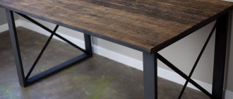
Both serial and home-made coordinate-type tables can be made on the basis of welded steel frames, which demonstrate high reliability. When making such a frame with your own hands, you should keep in mind that welded joints do not withstand vibration loads well, so in the finished structure it is necessary to get rid of internal stresses as much as possible. This is achieved through appropriate heat treatment (tempering).
Coordinate tables, depending on their purpose, can be made according to two design schemes:
- cross;
- portal
Tables made according to the first scheme are equipped with universal drilling machines, on which parts of complex configurations are processed. The design features of such devices allow access to the workpiece being processed from three sides. Portal-type tables are equipped with machines on which holes are drilled in sheet blanks.
Gantry 3-axis CNC table
Materials and tools used
To work you will need a welding machine, a drilling machine, an angle grinder with discs, a hammer, brushes, and a corner. At the preparatory stage, it is necessary to select the material for the base of the device, the control mechanism and guides. The accuracy of the future operation of the device, service life, reliability of the device, and financial costs of manufacturing depend on the correct choice of these components. To create a base, one of three metals is suitable:
- cast iron;
- steel;
- aluminum.
The first material is rarely used in work. The reason lies in its fragility, heavy weight, and fragility. Steel wins by these criteria, which is why it is often used in production. Its only drawback is its high cost. Aluminum is much more affordable. Its advantages are lightness and softness. But it is only suitable for small-sized tables, since the malleable metal cannot withstand large heavy parts.
Making your own changing table and mattress for it
When making a coordinate table with your own hands, you need to think about what type of drive the device will have. According to the control method, manipulators are divided into three types: mechanical, electrical, and program control. The latter drive is not used in self-production. The electrical analogue gives a small error, but in private conditions it is problematic to use. For personal home appliances, a more suitable type of control is mechanical. However, it has a drawback - the lack of perfect accuracy.
For manual production, rail or cylindrical guides are suitable.
Cast IronSteel
Aluminum
Mechanical drive
Electric
Software controlled
Advantages and disadvantages of a homemade stand
The following advantages of homemade devices are highlighted:
- A homemade machine is very cheap.
- When constructing the device, you can use parts left over from old equipment.
- All drawings and detailed manufacturing algorithms can be found in the public domain.
- You can make a very high-quality and technologically advanced model. You have the opportunity to make a truly high-quality device.
However, there are also disadvantages:
- To manufacture parts, special equipment will be required.
- If the guide is of poor quality, this will greatly affect the drilling accuracy.
- It is very difficult to make a mechanism superior in quality and functionality to the factory one.
Guide bed
The bed is one of the most important parts of a drill machine. It can be constructed of metal or wood. The thickness and dimensions of the frame depend on the weight of the structure and the tool. The size of the bed also depends on the type of operations performed on the machine:
- Dimensions 50 by 50 millimeters are used for drilling.
- 100 to 50 for more complex operations.
A stand is attached to the frame, which can be attached using screws; it is important to understand that it must be strong enough
Guide post
The stand can also be made of wood or metal. It consists of guides (a rail for tool movement) and a clamp for fixing the tool at the same level. Its production proceeds as follows:
- Secure the stand to the frame.
- Attaching the guide to the rack.
- Install the carriage, which should be located on the guides.
The tool can be mounted on a stand using clamps or a special block
How to make a drill machine with your own hands.
To make a drill machine we will need the following materials:
- Plastic bottle.
- Plastic cover.
- Drill.
- Stationery knife.
- Marker or felt-tip pen for marking.
- Universal glue.
Homemade device guide stand
Equipment use
Before starting to operate the coordinate base, the master must study the safety rules, equipment features, as well as the lighting requirements in the room where the work is taking place.
The table is activated in the following ways:
- mechanical movement;
- use of electric drive;
- installation of CNC equipment.
The first or second option, if you implement it yourself, will be the most suitable.
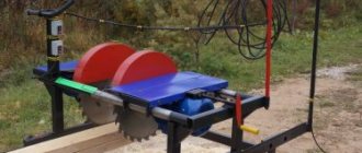
Separately, it is worth mentioning such design options as a rotary table and a cross.
The first one is capable of rotating around its own axis and is the most convenient option if you need to process parts with axial symmetry, round and disc-shaped workpieces.
The cross drill table is more common in everyday use and provides the ability to move the workpiece in two directions: X and Y.
Now make the stop
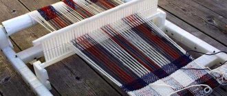
1. Cut out the blanks for support F , front plate G , lower H and upper I parts of the stop according to the specified dimensions. Install a 10 mm thick groove disk into the sawing machine and adjust the longitudinal (parallel) stop for sawing tongues exactly in the middle of the thickness of parts H and I (Fig. 3 and 4). Then cut 5mm deep tongues into these parts and mark the edges that fit against the saw stop. When cutting out the upper and lower tongues on the lower fly, in both cases, guide the workpiece along the stop with the same edge. Now, without changing the settings, cut out the tongue in the support blank.
Pressing the parts with their marked edges against the back side of the pad G, glue the lower H and upper I parts of the stop together, with the lower support F and the pad G. The clamps should compress the gluing in two directions.
2. Glue the front pad blank G to the support blank F (Fig. 4). Make sure the pad is glued to the support at an exact 90° angle. When the glue has dried, glue the lower H and upper I parts of the stop (photo B). Before the glue dries, insert 10mm diameter steel rods into the square holes, pushing them all the way through to remove any excess glue squeezed out from inside.
3. Cut out a 19×10 mm tongue on the front side of the lining G to install the guide aluminum profile (Fig. 4). Then cut a 3x3 mm dustproof fold along the bottom edge of the trim.
4. Saw one end of the assembled stop evenly, and then cut the workpiece into three parts (Fig. 3), obtaining a stop 572 mm long and two extensions of 89 mm each. Then saw off part of the support on the extensions (Fig. 4).
5. Using a flexible template, mark semicircular cutouts on the upper edge of the stop and the rear edge of the support F (Fig. 3). Cut out the cutouts with a jigsaw or band saw and sand smooth. Then drill 6mm holes for the screws that secure the fence to the table and a hole for the drill chuck key in the base where indicated.
6. To install threaded bushings in part I , drill holes with a diameter of 11 mm into the upper square hole of the stop (Fig. 3 and 4) . Apply epoxy glue to the walls of these holes and insert threaded bushings. Once the glue has completely cured, use a 10mm drill bit to remove any excess glue that may have gotten into the square holes for the steel bars. For additional tips on installing threaded bushings, see the “Tip from the Expert.”
Master's advice. Installing threaded bushings
Homemade workshop fixtures often use various screws for fixation or adjustment. In order for them to work in wood and plywood parts, threaded bushings will be required. They are available in different sizes (metric - from M4 to M10). There are two main types - drive-in and screw-in (futorki), as shown in the left photo below.
Use screw-in bushings in softwood and plywood where large external threads easily crush surrounding wood. Simply drill a hole whose diameter is equal to the diameter of the bushing body and screw the bushing into it. In hardwoods such as oak or maple, or when the bushing must be positioned near the edge of a piece and could split the wood, drill a hole slightly larger than the outside diameter of the threads and insert the bushing with epoxy glue into it. To avoid staining the internal thread of the bushing with glue, seal its end (photo above right).
Drive-in sleeves with burrs on the outside are equally suitable for plywood, hardwood and softwood. Drill a hole whose diameter is equal to the diameter of the bushing body and insert the bushing using a clamp or hammer and a block of wood. In cases where the force of the clamping screw pulls the sleeve out of the material (for example, a screw with a hand-grip handle that secures the steel rods of the stop extensions), drill a hole of such a diameter that only the tips of the burrs touch its walls, and insert the sleeve into it with epoxy glue.
Useful tips
The instructions, which describe how to make a coordinate table with your own hands, explain the process step by step. However, minor problems may arise during operation. To avoid them, it is recommended to adhere to safety precautions and take into account the advice of experts. The most important of them:
- if you plan to process plastic or wood, then the base of the manipulator can be made of aluminum;
- with device dimensions of 35 x 35 cm, it is advisable to adjust the total length of the guides to 30 cm;
- to protect the device from chips before installation, it is recommended to place a piece of plywood under it;
- when using cylindrical guides, there is no possibility of connecting a lubrication supply system, so all parts must be lubricated manually;
- When assembling, it should be taken into account that the plain bearing provides better machining accuracy, while its counterpart (friction bearing) leads to some play.
Making a table for a laptop with a cooling system with your own hands
To carry out welding work, safety precautions must be observed. It involves the use of special clothing, a protective mask (shield), suede or tarpaulin gloves. The room in which the assembly is carried out must be ventilated or have a high-quality exhaust hood. When working outdoors, a canopy is required. Near the workplace, means and materials must be prepared to extinguish a possible fire.
The manufacture of a simple type coordinate manipulator can be mastered by a master with welding skills . It is not difficult to obtain a reliable and convenient product if you strictly follow the conditions of the drawing and the assembly algorithm. The home device allows you to engage in small-scale production of metal, wood, and plastic parts. The service life of such a device depends entirely on the quality of installation and the volume of drilling and milling work performed.
This is interesting: Design features of argon arc welding machines
Do-it-yourself desktop drilling machine: diagrams and drawings
You don't have to spend money on a benchtop drill press because it's not that difficult to make your own. To do this, you will need to purchase, manufacture or use used parts. We will tell you about creating several designs, and you can choose your model for assembly.
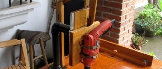
Almost every owner who builds or repairs his house or apartment, repairs household and garden equipment, and various crafts made of metal and wood has a drill.
But for some operations, a drill is not enough: you need special precision, you want to drill a hole at a right angle in a thick board, or you just want to make your work easier.
To do this, you will need a machine that can be made on the basis of various drives, machine parts or household appliances, and other available materials.
The type of drive is a fundamental difference in the designs of homemade drilling machines. Some of them are made using a drill, mostly electric, others using motors, most often from unnecessary household appliances.
Tabletop drilling machine made from drill
The most common design can be considered a machine made from a hand or electric drill, which can be made removable, so that it can be used outside the machine, or stationary. In the latter case, the switching device can be moved to the frame for greater convenience.
Main elements of the machine
The main elements of the machine are:
- drill;
- base;
- rack;
- drill mount;
- feed mechanism.
The base or frame can be made from a solid cut of hard wood, furniture board or chipboard. Some people prefer a metal plate, channel or tee as a base.
The bed must be massive to ensure structural stability and compensate for vibrations during drilling to produce neat and accurate holes. The size of the frame made of wood is at least 600x600x30 mm, of sheet steel - 500x500x15 mm.
For greater stability, the base can be made with eyes or holes for bolts and attached to the workbench.
The stand can be made of timber, round or square steel pipe. Some craftsmen use the frame of an old photographic enlarger, a substandard school microscope, and other parts that have a suitable configuration, strength and weight as a base and stand.
The drill is secured using clamps or brackets with a hole in the center. The bracket is more reliable and provides greater accuracy when drilling.
Design features of the drill feed mechanism
The feed mechanism is needed to move the drill vertically along the stand and can be:
- spring;
- articulated;
- screw jack type design.
Depending on the type of mechanism adopted, the type and structure of the rack will also differ.
The drawings and photos show the basic designs of tabletop drilling machines, which can be made from electric and hand drills.
With a spring mechanism: 1 - stand; 2 - metal or wooden profile; 3 — slider; 4 - hand drill; 5 — clamp for fastening the drill; 6 — screws for fastening the clamp; 7 - spring; 8 — square for securing the stand 2 pcs.
; 9 - screws; 10 — stop for the spring; 11 — wing bolt for fastening the stop; 12 — base of the machine With a spring-lever mechanism With a spring-hinge mechanism: 1 — bed; 2 — washer; 3 — M16 nut; 4 — shock-absorbing struts 4 pcs.
; 5 - plate; 6 — bolt M6x16; 7 - power supply; 8 — thrust; 9 - spring; 10 — M8x20 bolt with nut and washers; 11 — drill chuck; 12 - shaft; 13 - cover; 14 — handle; 15 — bolt M8x20; 16 — holder; 17 — rack; 18 — cup with bearing; 19 — engine With a hinged springless mechanism Rack operating on the principle of a screw jack: 1 — frame; 2 - guide groove; 3 - M16 thread; 4 - bushing; 5 - nut welded to the bushing; 6 - drill; 7 - handle, when rotated, the drill moves up or down. Drilling and milling machine: 1 - base of the machine; 2 — supports for the table lifting plate 2 pcs.; 3 - lifting plate; 4 — handle for lifting the table; 5 - movable drill holder; 6 — additional rack; 7 — screw for fixing the drill holder; 8 — clamp for fastening the drill; 9 — main rack; 10 — lead screw; 11 - drum with Vernier scale Machine made from a car jack and drill Carriage made from furniture guides Mini machine from a decommissioned microscope Base and stand from an old photographic enlarger
Machine made from a hand drill: 1 - bed; 2 — steel clamps; 3 — grooves for attaching a drill; 4 — drill fastening nut; 5 - drill; 6 - slider; 7 — guide tubes
Machine based on the steering rack of a passenger car
A steering rack for a car and a drill are quite massive products, so the frame should also be massive and, preferably, with the ability to attach the machine to a workbench. All elements are welded, since connections with bolts and screws may not be sufficient.
The frame and support post are welded from channels or other suitable rolled products, about 5 mm thick. The steering rack is secured to a stand, which should be 70–80 mm longer than the rack, through the eyes of the steering column.
To make the machine more convenient to use, the drill control is placed in a separate unit.
5. Drilling machine based on a steering rack from Moskvich
Assembly procedure for tabletop drilling machines:
- preparation of all elements;
- attaching the stand to the frame (check verticality!);
- assembly of the movement mechanism;
- fastening the mechanism to the rack;
- fastening the drill (check verticality!).
All fastenings must be made as securely as possible. It is advisable to join one-piece steel structures by welding. When using any kind of guides, you need to make sure that there is no lateral play during movement.
Advice! To fix the part in which the hole is drilled, the machine can be equipped with a vice.
You can also find ready-made stands for drills on sale. When purchasing, you need to pay attention to the weight of the structure and the size of the working surface. Lightweight (up to 3 kg) and inexpensive (up to 1.5 thousand rubles) racks are suitable for making holes in a thin plywood sheet.
Drilling machine using asynchronous motor
If there is no drill on the farm or it is not desirable to use it in the machine, you can make a design based on an asynchronous motor, for example, from an old washing machine. The design and manufacturing process of such a machine are quite complex, so it is best to make it by a craftsman with sufficient experience in turning and milling work, and assembling electrical circuits.
Evaluate the complexity of the work from the drawings we provide in this article.
The device of a drilling machine with a motor from household appliances
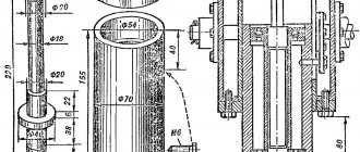
To familiarize yourself with the design, we provide assembly drawings and detailing, as well as the characteristics of assembly units in the specifications.
Drawing of a drilling machine with motor
Parts and materials for manufacturing the machine are shown in the table:
Table 1
Pos.
Detail Characteristics Description 1 Bed Textolite plate, 300 × 175 mm, δ 16 mm 2 Heel Steel circle, Ø 80 mm Can be welded 3 Main stand Steel circle, Ø 28 mm, L = 430 mm One end is turned to a length of 20 mm and threaded M124 Spring L = 100–12 0 mm 5 Bushing Steel circle, Ø 45 mm 6 Locking screw M6 with plastic head 7 Lead screw Тr16х2, L = 200 mm From the clamp 8 Matrix nut Тr16х2 9 Drive console Steel sheet, δ 5 mm 10 Lead screw bracket Duralumin sheet, δ 10 mm 11 Special nut М12 12 Travel flywheel screwsPlastic 13Washers 14Four-ribbed block of drive pulleys of the V-belt driveDuralumin circle, Ø 69 mmChange spindle rotation speed is performed by moving the drive belt from one groove to another 15 Electric motor 16 Capacitor block 17 Driven pulley block Duralumin circle, Ø 98 mm 18 Return spring limit rod M5 screw with plastic mushroom 19 Spindle return spring L = 86, 8 turns, Ø 25, wire Ø1.2 20 Split clampDuralumin circle, Ø 76 mm 21 Spindle head, see below 22 Spindle head console Duralumin sheet, δ 10 mm 23 Drive belt Profile 0 Drive V-belt with “zero” profile, so the pulley block runners have the same profile 24 Switch 25 Power cable with plug 26 Tool feed lever Steel sheet, δ 4 mm 27 Removable lever handleSteel pipe , Ø 12 mm 28ChuckTool chuck No. 2 29M6 screw with washer
Drive consoleFour-strand drive pulley blockDriven pulley blockReturn spring limit rodSplit clampSpindle head console
The spindle head provides both translational and rotational motion. It is mounted on its own base - a duralumin console.
Spindle head drawing
Parts and materials for manufacturing the spindle head are shown in the table:
table 2
Pos.
Part Characteristics 1 Spindle Steel circle Ø 12 mm2 Running sleeve Steel pipe Ø 28x3 mm3 Bearing 2 pcs. Radial rolling bearing No. 10009004 Screw M65 Spacer washers Bronze 6 Lever Steel sheet δ 4 mm7 Running sleeve stopper Special M6 screw with knurled button 8 Nut Bottom nut M129 Stationary bushing Steel circle Ø 50 mm or pipe Ø 50x11 mm10 Bearing Radial contact 11 Split retaining ring 12 End adapter sleeve Steel circle Ø 20 mm
Spindle
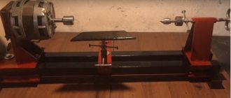
Running bushing Running bushing stopper Stationary bushing End adapter bushing Drill head assembled Drilling machine assembled
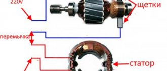
The electrical circuit depends on the type of engine.
A simple electrical circuit for a factory machine 2M112
Manufacturing instructions
Once the type of material and type of construction have been selected, they proceed directly to work. At the first stage, it is necessary to draw up an accurate drawing indicating the dimensions of all parts. If there is no ready-made scheme, you should develop it yourself. The final result is largely determined by the accuracy of the location of the parts relative to each other. The process of assembling a coordinate table with a mechanical drive consists of the following steps:
- the main assembly is welded from a metal profile 2 mm thick;
- check the geometry of the cross and clean the seams with a grinder;
- a block of guides is assembled on the welded central unit (travel is 94 mm);
- nuts of size M10 are installed inside the profile;
- a handle with a bearing is assembled on a threaded rod (M10);
- weld the base from a corner having a U-shaped configuration;
- screw all parts onto the built-in nuts;
- lubricate moving elements with technical oil;
- install the device on the bed of the milling machine.
The manipulator structure should be assembled on an absolutely flat surface.
Rotary table cost
Stores offer a wide range of rotary tables for milling machines. The table shows approximate prices for some typical rotary tables that have not been used.
| Construction type | Approximate price, rub. |
| Round milling | 40 000 |
| Sinus | 48 000 |
| Rotary round (manual or mechanized drive) | 80 000 |
| Vertical with mechanized drive | 75 000 |
| Horizontal-vertical (Poland) | 113 000 |
| With mechanical reference system (Russia) | 200 000 |
| Globusny | 313 000 |
The cost of a rotary table depends on its type, design, the presence of additional elements, the need for commissioning work and the manufacturer.
Production of homemade versions
When manufacturing, you should initially select the material of manufacture:
- Cast iron is an expensive, heavy, brittle material. It is quite rarely used in the production of a drilling machine.
- Steel is a strong, hard, durable metal, which also has a fairly high cost. Steel can be called the most attractive material.
- Aluminum is a light, fusible, but expensive and soft material. It is quite easy to use in the manufacture of any machine parts. As a rule, mini equipment is created using this alloy.
The above materials are selected for a full or mini machine.
Base material
Before you start creating a device, you need to think about what materials and spare parts to use. Preliminary preparation is necessary so that they can give the future creation the following characteristics:
- Normal working weight so that one person can work with such a table without noticeable difficulty.
- Simplicity and versatility of installation. A good product must be suitable for different types of drilling equipment.
- Maximum cost savings on manufacturing. If development turns out to be too expensive, wouldn’t it be easier to buy a ready-made item?
Most often, these requirements are met by the following common and economical options:
- steel;
- metal;
- cast iron;
- aluminum;
- duralumin.
If the table is needed mainly for drilling soft materials (wood, plastic), then aluminum will be the best option. It is extremely light and has sufficient strength.
If you have to work with metals, drill serious parts to a relatively large depth, then you will need something more durable - steel, cast iron, iron. These are heavy materials, but the loads they can withstand are impressive.
Advantages and disadvantages of self-production
A coordinate table is an additional structure to a milling, drilling metal or woodworking machine. Thanks to it, you can increase equipment productivity by reducing the labor intensity of the parts processing process. The workpiece is simply fixed on the working surface and can move smoothly along a given path.
Homemade coordinate tables have the following advantages:
- small dimensions;
- simple design form;
- controlled mechanically;
- used in handicraft production.
Their main advantage is saving money. Making such a design from scratch will cost much less than buying a factory-made manipulator. Of course, there are a number of difficulties when making it yourself. A suitable drawing is needed, according to which the required trajectory of the workpiece will be set. If there is no someone else’s experience, then you will have to create it yourself, but any error when drawing the diagram will make itself felt during work. In addition, a homemade table is only suitable for small-scale production, since the simplest homemade mechanisms wear out much faster than factory ones.
For mass production of parts and their processing, only a factory model of a coordinate table is suitable.
Simple design formSmall dimensions
Mechanical control
Saving money
Homemade tilt-rotary machine for metal and wood machines
In a home workshop where there is a milling machine, it is good to have a rotary table among the devices. They are sold in stores if you need to make a lot of parts. Hobbyists can make the device themselves.
Required tools and materials
The easiest way to make a device yourself is from a lathe chuck. To do this you will need the following tools:
- screwdriver;
- Bulgarian;
- hex and socket wrenches;
- welding machine.
The rotary table consists of parts:
- scroll chuck;
- base with 2 ears;
- limb from the drawing board;
- clamps;
- bolts;
- 2 disks.
Ears with holes for bolts are welded to the base for fastening to the working surface of the machine. The limb is installed between 2 washers above the base. An inspection window is cut out in the body of the cartridge to see the divisions. The part is clamped into the jaws and rotated manually.
Drawings and calculations: When making a device yourself from scrap materials, a calculation is made of the stroke of the worm shaft and the number of teeth on the disk through its radius. Then a tap with the required pitch for cutting the disk is selected.
Step-by-step instruction
The disk is fixed on the workbench and put on the axle. Fasteners are installed. A screw is screwed in near the edge, against which the tap inserted into the electric drill rests. On its side it rests against the surface of the disk. When rotated, it cuts the tooth. The worm is installed in the housing in engagement with the cut teeth on the disk. A dial with a handle is attached to its end. Everything is attached to the base.
Safety precautions
When making a device, it is necessary to check the condition of the tool and the wires of the electric drill and welding machine, the grounding of the equipment and sockets. Even in a home workshop, you should wear overalls with long sleeves and safety glasses. The workplace must be cleared of unnecessary objects and well lit.
A rotary table for a milling machine increases the functionality of the equipment and allows you to make more complex parts with less time. For home use, you can make the device yourself.
Guides
The guides along which the coordinate table moves are an important element of its design, since not only the smooth movement of the part, but also the accuracy of its processing depends on their quality and design features. Both in serial models and in homemade coordinate tables, the guides can be of rail or cylindrical type.
Smooth and accurate movement along the guides is ensured by the built-in carriage and bearing units. In cases where increased movement accuracy is required from the coordinate table, sliding bearings are used in its guides, since rolling bearings create significant play in the supports, although they reduce the friction force more effectively.
Bearing unit design
Guides for coordinate tables, depending on the type of carriage, are:
- equipped with an enlarged flange used to attach the structure to the bottom of the table;
- wafer-type, which are fastened in the usual way.
Dovetail guide
Rotary tilt table of a milling machine: parameters for optimal selection
The main characteristic of such systems is the amplitude of movement. Depending on this indicator, devices can even be installed on drilling machines. In this case, it becomes possible to obtain holes whose axis is located vertically, at an angle of 90° to the main plane of the part. Fixation when turning is carried out using a crank mechanism equipped with locking latches. If there is a dividing disk, it is possible to carry out metal-cutting operations simultaneously with several workpieces. The faceplate of such units is fixed in a certain position using the tailstock.
Technological characteristics of devices that should be taken into account when choosing their suitable design:
- Rotation angle, degrees – up to 360°.
- Tilt accuracy, degrees – no more than 0.08.
- The shape of the mounting hole for connection to the main table of the machine is a Morse cone.
- Dimensions and number of T-slots (set according to individual order, but usually 12 mm in width, and 6 pcs. in quantity).
- The diameter (for round versions) is selected from the size range 160, 250, 400, 630, 1000, 1250, 1600 and 2500 mm. Larger units are manufactured according to special orders, and for machines of certain models, including those with CNC.
Regarding manually controlled options, the requirements for the worm mechanism are additionally established - gear ratio, accuracy of dial and pitch circle graduation, as well as the worm module and the distance between the geometric center of the reference plane and the control mechanism.
For vertical and universal rotary tables of CNC machines, the limit of vertical adjustment of their relative position should be 0...90±5°.
To ensure rotation accuracy, special limiting screws are used, which are installed on the vertical ends of the faceplate. The movement is carried out by turning on the micro-clutch, which is blocked when the milling head is running.
Rotary tables usually have a mechanical reference system, using measuring dials, but modern designs use a digital control system, with coordinates indicated on a display device (used on machines equipped with CNC).
Rotary horizontal-vertical table for milling or planing machines: parameters for optimal selection
Such units are designed for processing products that do not require frequent reinstallation. Structurally, this option is the most budget-friendly and is available for installation on any milling equipment, including small-sized ones.
It is possible to produce the following transitions:
- circular milling;
- processing of ledges and platforms with horizontal sections;
- corner elements.
The installation of this type of device is especially effective for machines that are not equipped with a device for longitudinal-transverse movement of milled products, and are not equipped with CNC. The movement is carried out by ball screws or rack and pinion gears (for more massive designs, rack and pinion drives are used).
The selection options are:
- overall dimensions of the structure in plan (length×width), mm;
- number of T-slots;
- faceplate thickness;
- a method of attaching a rotary table to the supporting surface of the machine (Morse tapers).
When choosing the type of drive, the smoothness of its operation, the accuracy of fixation when processing the workpiece, the additional loads on the drive, the required tilt angle, and the milling/planing speed are taken into account.
Homemade rotary tables for milling machines make it possible to increase the accuracy of processing in a home workshop. They are small in size (diameter 100 mm), easy to assemble and easy to use. For self-assembly you will need:
- scroll chuck;
- corner limb and two disks for fixing it;
- round washer with welded “ears” for the base;
- bolts.
It is attached to the tabletop of the milling machine using clamps. This rotary table device simplifies the process of processing small parts on a router.
Having woodworking skills, you can make a milling table with your own hands. The sequence of actions is as follows:
- Based on the dimensions of the workpieces being processed and the availability of free space in the workshop, determine the parameters of the table.
- Make a tabletop (from MDF or plywood 19...25 mm thick). Drill the necessary holes and cutouts in the surface.
- Make a base large enough to accommodate the router.
- Install the mounting plate.
- Modify the stops.
It is important to first think through its design taking into account individual needs, draw up a drawing, accurately mark and cut out the blanks.
Design selection
When choosing a design, you need to decide on its dimensions. If equipment that processes a part will be installed on a coordinate table, then its dimensions must be taken into account. If it is needed to fix the workpiece, it is mounted on the frame of the drilling equipment, and its width and length will be about 35 x 35 cm.
Tables are also distinguished by the type of fastening:
- When making a coordinate table with your own hands, the structure is equipped with a mechanical fastener. This is the simplest solution in terms of implementation, but it has a number of disadvantages. For example, it often leads to processing errors, and there is a risk of deformation of the product surface.
- Vacuum fastening is considered the best option. With its help, precise positioning of the workpiece on a horizontal plane is ensured. When an air stream is supplied into the gap between the tabletop and the workpiece, the pressure in this area changes. Thanks to this, it is possible to perform processing more efficiently (without mechanical damage to the product).
- Workpiece weight clamping is suitable when using a drill press to machine heavy parts. Due to its mass, the base product remains in the same place even with strong impact.
The functionality of the table depends on the number of degrees of freedom:
- If there is only one, then the workpiece can only be moved in one direction (this is a good option for processing flat products).
- If there are two degrees, it becomes possible to move the workpiece along X and Y coordinates.
- If there are three of them, then the part can move up, down and along the Z coordinate.
If the table is made for home production and processing of parts, then using two degrees of freedom is more than enough.
When making a coordinate table with your own hands, it is important to decide for what purpose it will be used. The parameters of the manipulator are selected in accordance with the dimensions, weight and shape of future workpieces. To work with various parts from metal and wood, a complex multifunctional mechanism is made. Usually, home craftsmen have enough capabilities of a small-sized table with mechanical fasteners and two degrees of freedom.
Mechanical
Vacuum
Fastening under the weight of the workpiece
Classification
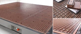
The unit in question is a carefully polished surface, where there are so-called T-shaped grooves intended for positioning the workpiece. The grooves are placed either along a circular arc or in the longitudinal direction (less often - in the transverse direction). Accordingly, a distinction is made between round and rectangular rotary tables.
With the presence of such a unit, metal removal (during milling, planing and other similar operations) can be carried out simultaneously in three coordinates X, Y, Z, and with simultaneous rotation of the workpiece to any required angle. Functionality is especially enhanced if the horizontal rotary table is installed on a machine equipped with a CNC system. In this case, high-precision design of such complex transitions as spiral grooves, round radius transitions and other contour elements of increased complexity is permissible.
The rotary table can be designed and manufactured in the following options:
- Round: here it is possible to process workpieces along a circular arc or obtain helical surfaces. When placing T-slots along an arc, several initial workpieces can be installed simultaneously.
- Vertically tiltable rotary table: it allows milling operations on composite structures, including those located perpendicular to each other.
- Vertically tiltable with rotary disks: if they are present on the machine, you can perform milling operations with several workpieces without reinstalling them.
- Horizontal rotary table, which provides the opportunity for milling work with workpieces of increased overall dimensions; This design option is suitable for small-sized equipment.
- Rotary table equipped with a vacuum grip. With this design, the milled workpiece can be fixed on any plane, in horizontal/vertical positions, and at any angle. Used on CNC machines.
Materials and mechanisms of structural elements
The durability of the structure and cost depend on the material of the product. You should immediately decide what type of table it will be - steel, aluminum or cast iron. The second important step is to decide on the control mechanism. You should also decide whether the drive should be mechanical or electric. The third step is to select guides. This will affect the processing accuracy of the workpieces.
Base
The following materials are used for the base:
- Cast iron. Expensive, heavy material turns out to be very fragile in operation, so it is used extremely rarely in the production of a drilling machine.
- Steel. The material is the most highly durable and durable. Its main drawback is the cost. Not every master will be able to purchase it.
- Aluminum. Light and soft material is easier to work with. It is not as expensive as steel. But it is not suitable for making a large-sized table, since it will not withstand the heavy weight of large workpieces. This is an ideal option for creating mini-equipment.
If the master processes metal workpieces, then it is better to make the table from steel or cast iron. True, you should immediately evaluate your costs: perhaps purchasing a ready-made manipulator will cost less than expensive hardware. An aluminum tabletop is suitable for working with wood or plastic.
Cast IronSteel
Aluminum
Drive unit
The drive is a control mechanism with which the coordinate table will change its position. It happens:
- Mechanical. The easiest way is to make it yourself. It allows you to significantly reduce the cost of the table. The basis is a conventional screw or belt drive - this is enough to set up small-scale production. Mechanics are not capable of providing 100% accuracy, and this is its clear drawback.
- Electric. It guarantees zero error when performing work operations, but it is very difficult to do it yourself. Often found in factory models of tables. If there is no own power source near the workplace, this option will not work.
Models with CNC (computer numerical control) should be included in a separate category of coordinate tables. This is high-tech equipment that is used by large enterprises for production in huge volumes. Their main advantages: good performance, as well as complete or partial automation of the process. Disadvantages: high cost, such a drive is not suitable for some parts.
Mechanical
Electric CNC
Guides
The accuracy of the workpiece processing depends on these elements, so they need to be selected correctly. Among those that you can do with your own hands, the following are distinguished:
- Rail. Rectangular guides are considered structurally more advanced. When using them, lower friction losses are observed and serious errors are avoided. It is possible to connect a lubricant supply system.
- Cylindrical. The use of rounded guides is fraught with high heating due to friction. They are suitable for machines of the so-called small category, but you will have to lubricate all the mechanisms manually.
The guides are made with a carriage and bearing units. The use of plain bearings will ensure high precision machining of the part. The use of a rolling shaft support will reduce friction and extend the service life of the manipulator.
The rolling bearing can cause noticeable play, which reduces the accuracy of the workpiece.
The carriage is a block of guides (mechanism assembly) that moves directly along them. It can provide increased flange dimensions, which allows it to be mounted on the underside of the table. If it is not there at all, then the carriage is placed on top (threaded method).
Rail guides and carriage
Cylindrical
Moving device
When choosing a moving device, you should answer a number of questions:
- What should the processing speed be?
- What positioning accuracy is acceptable when performing work operations.
- How productive the equipment will be used.
A belt moving device is most often used in the manufacture of homemade coordinate tables. It is cost-effective, but has a number of disadvantages. The belt wears out quite quickly and can also stretch during use. In addition, due to its slipping, the accuracy of the moving element is reduced.
Ball screw drive is a more durable and reliable option. Despite the small dimensions of the device, it has a good load capacity, and movement is carried out evenly and with great accuracy. Smooth and almost silent running, as well as high quality surface treatment are not all the advantages of ball screws. However, it also has some disadvantages: high cost and limitations in the speed of rotation of the propeller if its length is more than 150 cm.
Rack and pinion devices provide high speed and accuracy of work, withstand heavy loads, are easy to install and are reliable in operation. The error in rack transmission is extremely low. If their size does not fit, then they undergo a fitting operation.
Belting
Ball screwRack and pinion
Motion transmission mechanism
The most important part of the future device, no matter whether it is a rotary table for a drilling machine or a cross version, is the mechanism for transmitting movement from the control handles to the device.
It is best to make a drive with a mechanical type of movement; they are manually controlled. In this way, specialists can achieve greater accuracy of movements and high quality of work performed.
The components of the motion transmission mechanism are:
- racks and gears, gears;
- belt mechanisms;
- ball screw drives.
Ball Screws
Experts advise choosing the latter type of mechanism, especially when it comes to a cross table; it has many significant advantages:
- extremely small system play;
- the product moves very smoothly, without jerking;
- The ball screw operates quietly;
- under significant workloads it shows high stability.
Experts say that the disadvantage of the mechanism is the inability to achieve high operating speed, but if you are considering a cross table for a drilling machine, then high speed is usually not required.
To save money, the master needs to try to implement belt drives. They are simple and accessible, but have disadvantages:
- low accuracy;
- rapid wear;
- risk of belt breakage under load.
As a conclusion, we note that if a person decides to make a table for a drilling machine with his own hands, then there is nothing fundamentally unrealistic about this. A basic set of materials and tools will help you quickly complete the task. The task for a specialist is to choose the right type of structure and produce high-quality all the critical components of the future device.
Step-by-step algorithm for manufacturing a household table with a mechanical drive
To make a coordinate table with the simplest mechanical drive, you must follow the instructions:
- It is necessary to make the central unit of the table in the form of a cross from metal profiles 20 x 20 cm (2 mm thick). It must ensure the stability of the entire structure, so all parts are welded.
- On the surface of the finished cross, assemble carriages with a stroke of 94 mm.
- File the profiles and then insert M10 nuts into them.
- Using M10 studs, assemble the handles with the bearing assembly.
- Next, you should weld two U-shaped bases from the corner, and then assemble the entire structure using bolts that were screwed into the previously pressed nuts.
- Wipe all components, as well as moving parts, with lubricant.
- The assembled table must be attached to the drilling machine bed.
To protect the lubricated structural elements from chips or other waste when processing the workpiece, it is advisable to lay plywood between the coordinate table and the machine. The dimensions of the finished manipulator will be 35 x 35 cm, and the thickness of the product will be 6.5 cm. It is desirable that the total length of the guides be about 30 cm.
Make the central unit of the table in the form of a cross
Assemble the carriages on the surface of the finished cross, process the profiles with a file, insert the nuts
Assemble the handles with the bearing assembly on the studs
Weld two U-shaped bases from a corner
Assemble the entire structure. Wipe all components and moving parts with lubricant.
Attach to drill press bed