- With replaceable gears, provide a large count. feeds limited by range. Used in dilapidated settings.
- With movable wheels. Used for frequent rebuilding of universal machines.
- With counter cones and draw key (easy control, 8-10 steps). Used in drilling lathes and turrets.
- Norton boxes (transmission with ring wheel).
- Guitar-shaped interchangeable wheels. They allow you to adjust the feed with any degree of accuracy (Umin=1/8).
- The Meander mechanism is a three-shaft mechanism consisting of a series of 2-wheel blocks with a ring gear. Advantage: single lever control, small axial dimensions.
Overview and diagrams of common models
Among the diverse model range and several generations of machines that are produced by our production, there are several models that continue to be popular for their technical characteristics and universal properties.
All of them are used in production or in domestic conditions to this day. At the same time, they continue to be worthy competitors to foreign analogues.
These are reliable, durable and durable devices capable of performing a huge number of different functions.
1L532
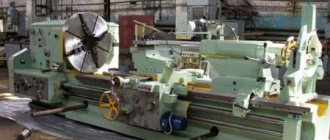
One of the most popular machines in the former USSR, which can successfully process workpieces of medium and large sizes.
At one time, this equipment was successfully exported to many countries around the world. Accuracy class – N. Machine weight – 43 tons.
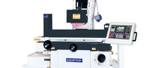
16U04P
High precision equipment. The largest diameter of the part processed above the bed is 200 mm. Machine weight – 750 kg.
1P611
A machine used in production, including for turning wheels of railway vehicles. According to GOST, they are distinguished by increased accuracy and have the ability to brake the spindle. Device weight 560 kg. Easily performs the following functions:
- Drilling.
- Segment.
- Cutting internal and external threads.
- Treatment of various surfaces.
The largest diameter of the workpiece above the bed is 250 mm.
1D601
This machine is better suited for purely domestic use. The accuracy is lower than the previous machine. It features high performance even after many years of operation.
Moving the caliper is only possible manually. The weight of the entire machine is about 30 kg. Due to the small dimensions, the maximum length of the workpiece to be processed is 18 cm.
16K40
One of the most popular models that has really gained popularity among craftsmen. Belongs to the middle class of equipment with accuracy class N.
Since 1932, several tens of thousands of various screw-cutting lathes have been produced in the USSR. They were used not only in production, but also for training young people, in schools, colleges, and many had desktop machines in garages, homes, and their own workshops.
Such equipment will help to bore a hole, level the required surface, or drill an existing hole. It is important, focusing on the initial specifications of the equipment, to purchase the most suitable model.
Drawings of the headstock of a screw-cutting lathe 1k62
Part numbers on the drawings should be read with the prefix 1K62. For example, if a part is designated 06-310, should read 1K62-06-310.
For parts whose numbers are underlined in the figures, consumption rates are given in Part 3 of the album.
Headstock of screw cutting lathe
Setting up the headstock of a screw-cutting lathe
Headstock of screw cutting lathe
Kinematic diagram of a screw-cutting lathe 1k62
Kinematic diagram of a screw-cutting lathe
Basic parameters of gears, worms, screws and nuts of the headstock of a 1k62 lathe
| the name of detail | Drawing number | Number of teeth or starts | Module or pitch, mm | Material | Heat treatment |
| VI axis gear | 1К62-02-103 | 60 | 2 | Steel 40Х | HRC46…54 |
| V axis gear | 1К62-02-104 | 26 | 4 | Steel 40Х | HRC45…50 |
| Gear-coupling 1st axis | 1К62-02-105 | 56,51 | 2,25 | Steel 40Х | HRC48…52 |
| Gear-coupling 1st axis | 1К62-02-106 | 50 | 2,25 | Steel 40Х | HRC48…52 |
| Gear III axis | 1K62-02-107 | 47,55,38 | 2,25 | Steel 40Х | HRC46…54 |
| Gear III axis | 1К62-02-108 | 65 | 3 | Steel 40X | HRC46…54 |
| Gear III axis | 1K62-02-109 | 45 | 3 | Steel 40Х | HRC45…50 |
| Gear III axis | 1К62-02-110 | 22 | 2,5 | Steel 40Х | HRC45…50 |
| VI axis gear | 1K62-02-113 | 22;45 | 2,5;3 | Steel 40Х | HRC48…52 |
| Gear XII axis | 1К62-02-114 | 35,56,42 | 2 | Steel 40Х | HRC48…52 |
| V axis gear | 1K62-02-115 | 45 | 3 | Steel 40Х | HRC48…52 |
| V axis gear | 1K62-02-116 | 88 | 2,5 | Steel 40Х | HRC45…50 |
| VIII axis gear | 1K62-02-117 | 60;45 | 2;3 | Steel 40Х | HRC48…52 |
| Gear II axis | 1К62-02-118 | 39;34 | 2,25 | Steel 40Х | HRC50…54 |
| VIII axis gear | 1K62-02-119 | 35;28 | 2 | Steel 40Х | HRC48…52 |
| Gear XIII axis | 1K62-02-120 | 28 | 2 | Steel 40Х | HRC48…52 |
| VII axis gear | 1К62-02-121 | 24;36 | 2,25 | Steel 40Х | HRC45…50 |
| Gear II axis | 1K62-02-122 | 38 | 2,25 | Steel 40Х | HRC50…54 |
| Gear II axis | 1K62-02-123 | 29 | 2,25 | Steel 40Х | NRS46…54 |
| Gear II axis | 1K62-02-124 | 21 | 2,25 | Steel 40Х | HRC48…52 |
| VIII axis gear | 1К62-02-125 | 42 | 2 | Steel 40Х | HRC48…52 |
| Gear IV axis | 1К62-02-276 | 45 | 3 | Steel 40Х | HRC45…50 |
| Gear IV axis | 1К62-02-277 | 88 | 2,5 | Steel 40Х | HRC48…52 |
| VI axis gear | 1K62-02-1016 | 52; 43 | 4; 3 | Steel 40Х | HRC46…54 |
Bearing layout for screw-cutting lathe 1k62
Specification of rolling bearings for lathe 1k62
Main bearing dimensions:
- inner ring diameter (d)
- outer ring diameter (D)
- bearing width (B)
| No. position according to the diagram | Bearing designation | GOST | Bearing type | Overall dimensions d, D, B mm | Quantity per machine |
| 1 | 209 | 8338-57 | Single row radial ball bearing | 45, 85, 19 | 4 |
| 2 | 7000108 | 8338-57 | -«- | 40, 68, 9 | 2 |
| 3 | 208 | 8338-57 | -«- | 40, 80, 18 | 4 |
| 4 | 7604 | 333-71 | Single row tapered roller bearing | 20, 52, 22,5 | 1 |
| 5 | 7605 | 333-72 | -«- | 25, 62, 22,5 | 1 |
| 6 | 7509 | 333-72 | -«- | 45, 85, 25 | 1 |
| 7 | 7306 | 333-72 | -«- | 30, 72, 21 | 2 |
| 8 | 7308 | 333-72 | -«- | 40, 90, 25,5 | 1 |
| 9 | 7309 | 333-72 | -«- | 45, 100, 27,5 | 1 |
| 10 | 7206 | 333-72 | -«- | 30, 62, 17,5 | 1 |
| 11 | А3182120 | 7634-56 | Double row radial roller bearing with short cylindrical rollers | 100, 150, 37 | 1 |
| 12 | A46215 | 831-62 | Single row angular contact ball bearing | 75, 130, 25 | 2 |
| 13 | 206 | 8338-57 | Single row radial ball bearing | 30, 62, 16 | 4 |
| 14 | 204 | 8338-57 | -«- | 20, 47, 14 | 1 |
| 15 | 205 | 8338-57 | -«- | 25, 52, 15 | 6 |
| 16 | 7506 | 333-71 | Single row tapered roller bearing | 25, 52, 16,5 | 1 |
| 17 | 7000106 | 8338-57 | Single row radial ball bearing | 30, 55, 9 | 11 |
| 18 | 7204 | 333-71 | Single row tapered roller bearing | 20, 47, 15,5 | 5 |
| 19 | 7203 | 333-71 | -«- | 17, 40, 13,5 | 2 |
| 20 | В8206 | 6874-54 | Single thrust ball bearing | 30, 52, 16 | 1 |
| 21 | B8106 | 6874-54 | -«- | 30, 47, 11 | 1 |
| 22 | 203 | 8338-57 | Single row radial ball bearing | 17, 40, 12 | 4 |
| 23 | 7205 | 333-71 | Single row tapered roller bearing | 25, 52, 16,5 | 4 |
| 24 | 7000107 | 8338-57 | Single row radial ball bearing | 35, 62, 9 | 2 |
| 25 | 2007106 | 333-71 | Single row tapered roller bearing | 30, 55, 17,2 | 1 |
| 26 | 709 | 8338-57 | Single row radial ball bearing | 45, 75, 11 | 2 |
| 27 | 8107 | 6874-54 | Single thrust ball bearing | 35, 53, 12 | 1 |
| 28 | 8205 | 6874-54 | -«- | 25, 47, 15 | 1 |
Repairing the headstock housing of a lathe
Restoring the holes for the spindle rolling bearings by boring and then pressing the bushings into the headstock housing is done in rare cases when there is significant wear on the holes, which cannot be compensated by appropriate adjustment of the bearings.
Provided that the spindle bearings are installed in special housings (machines) and flanges, the wear of the bearing holes is compensated by replacing the corresponding housings and flanges, followed by adjusting the internal diameter to the bearing and adjusting the radial runout (permissible deviation 0.01 mm).
When restoring holes by boring and installing compensation bushings, the headstock housing is repaired as follows.
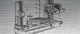
Initially, use a scraper to clean the burrs on the supporting surfaces 8 and 10 (Fig. 59, o) of the headstock housing 3 and in the holes for bearings 1 and 4. Then the worn hole is bored (in our case, the hole of the front bearing 4) on a horizontal boring machine 6 for subsequent pressing of the bushing.
The headstock body is installed on the table 9 of a horizontal boring machine with supporting surfaces 8 and 10. The installation accuracy is verified using indicators 2 and 5 on the mandrel 7 fixed in the spindle of the boring machine (the spindle axis must be parallel to the supporting surfaces 8 and 10). The installation is aligned using the undeveloped surfaces of holes 1 and 4 (permissible deviation 0.05 mm along the length of the part, installation accuracy 0.01 mm).
After securing the headstock body of the lathe to table 9 of the horizontal boring machine, the worn hole is bored to press in the bushing, and the inner size of the bushing should be taken with an allowance for boring, and the outer diameter of the bushing should be equal to the inner diameter plus 15-16 mm (permissible deviations: radial runout - no more than 0.01 mm; non-parallelism of the hole axis to the supporting surfaces 8 and 10 of the headstock base - no more than 0.01 mm over a length of 300 mm).
After pressing in bushing 1 (Fig. 59, b), it is necessary to bore it and trim the end to press in the bearing (permissible deviation - radial runout - no more than 0.01 mm).
The headstock housing is installed on the repaired frame guides and the correct installation and scraping of the supporting surfaces 8 and 10 are verified (Fig. 59, a). Then, control mandrel 1 is inserted into the conical hole of the spindle (Fig. 59, c) and using indicator 3 installed on bridge 2, the parallelism of the spindle axis in the horizontal and vertical planes is checked, while the bridge with the indicator is moved along the frame guides along the length of the mandrel.
If there are deviations above the permissible ones, the defect is eliminated by scraping the base of the body (supporting surfaces) of the headstock.
Non-parallelism of the spindle axis is allowed: in the vertical plane, the free end of the mandrel can only be above the horizontal axis (0.02 mm over a length of 300 mm); in the horizontal plane - no more than 0.02 mm over a length of 300 mm, and the free end of the mandrel can only be deflected towards the cutter.
After scraping, the number of paint prints should be at least 10 on an area of 25 X 25 mm.
To repair the headstock guides, it is necessary to install the spindle in its supports (bearings). The headstock with the spindle is placed on the frame guides, aligned to the level, and a control mandrel is inserted into the conical hole of the spindle (Fig. 59, c). A stand with an indicator 3 is installed on the caliper carriage or on the universal bridge 2, the measuring pin of which is sequentially brought to the upper and side generatrices of the mandrel. Then, deviations from parallelism are determined when the carriage moves along the bed guides. The guides are scraped according to the paint prints, taking into account the deviations noted on the control mandrel. The number of paint prints must be at least 10 on an area of 25 X 25 mm. Non-parallelism in the vertical plane is allowed no more than 0.02 mm over a length of 300 mm. The free end of the mandrel can only be tilted upward. Non-parallelism in the horizontal plane is allowed no more than 0.01 mm over a length of 300 mm. The free end of the mandrel may deviate towards the cutter.