Jig boring units have a special place in the world of machine tools, because they perform one of the most difficult tasks - creating high-precision holes with minor deviations in placement relative to each other. Such equipment has a special reading device, which makes it possible to perform high-precision processing of workpieces. The error when drilling holes is up to 1 micrometer. Additionally, coordinate machines are equipped with a device that controls possible deviations, which makes the work process almost like jewelry.
This type of technique is used in the processing of center-to-center holes if it is necessary to achieve the most accurate distances in accordance with the coordinates . During the processing of workpieces, no additional structures are needed to guide the tool.
Contents of delivery
The kit includes a variety of additional tools and special accessories to help you drill and bore holes, cut threads, mill and mark. We are talking about the following elements:
- Ammo.
- Adapter bushings.
- Mandrels for cutters.
- Set of boring bars.
- Universal tool holder.
- Fine feed tool holder.
- Microscope-centrifuge.
- Spring core.
- Installation center.
- Cutters, drills, reamers, taps.
Design Features
The horizontal jig boring metalworking machine has become very widespread, since the main components are conveniently located for processing large workpieces. The layout of a single-column and double-column jig boring machine is significantly different. An example is a single-column type boring and turning machine:
- The main part of the structure is represented by a frame on which all components are located.
- Boring on a modern jig boring machine is carried out by installing a special boring head. In some cases, it provides for quick tool changes. The tool of a modern jig boring machine can be attached through special equipment.
- Cross table. The operating principle of this equipment determines the ability to move workpieces in two directions.
Manufacturers produce two-column jig boring machines with the following components:
- It’s the same table on which the workpieces being installed are processed. They can be fixed in order to obtain a hole or several with precise relative position.
- Stand and bed. Many models provide for the location of the tool above the body or other part. The spindle can be very different.
- Boring head. The main technical characteristics are determined by the features of the installed boring head. Some equipment has heads with automatic tool change.
In almost all cases, a two-column jig boring machine or single-column type has a bed that consists of two flat and one T-shaped guide. The slide moves along these guides. Accuracy standards are maintained in accordance with GOST due to the precise positioning of all elements relative to each other. Control units can be located on a variety of structural elements: their types depend on which company produces the equipment and what control system is installed.
Electrical diagram of a jig boring machine using the example of 2A450MF
Equipment classification
Boring units have some design features. Depending on the type of work performed, equipment can be specialized or universal.
The main feature of units of this kind is the spindle (can be located in both horizontal and vertical positions), with the help of which the axial feed is driven. Since the equipment is adapted to perform different tasks , the workpiece often goes through a full processing cycle. It is important that the product does not need to be moved between several machines.
Therefore, boring machines are in particular demand in the mechanical engineering industry, where there is an urgent need for constant complex machining of parts. The main characteristic that influences the level of performance is the spindle cross-section. The working tool is fixed in it.
Surface treatment of workpieces on diamond boring machines
On diamond boring machines, the holes are finally machined with diamond and carbide cutters.
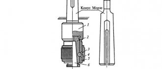
In Fig. 4.7.1 shows a one-piece diamond boring machine with a horizontal spindle. On the bed 1
Boring head
2 is installed.
A mandrel with a cutter is fixed in the head.
The workpiece is fixed on a table 3,
which moves along the frame guides - a longitudinal feed, the value of which is regulated by the feed mechanism
4.
Two coaxial holes are processed on double-acting diamond boring machines with two boring heads.
Rice. 4.7.1 General view of the diamond boring machine
High accuracy and low roughness of the machined surface are ensured by the use of high cutting speeds (200–1000 m/min), low feeds (0.01–0.1 mm/rev) and cutting depths (0.05–0.2 mm). When processing non-ferrous metals, diamond cutters are used, and when processing ferrous metals, carbide cutters are used.
Diamond boring machines are widely used for boring holes in cylinder blocks and liners of tractor, automobile and motorcycle engines.
Technological requirements for the designs of machine parts processed on boring machines
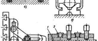
Holes in body parts should be of simple shape (Fig. 4.8.1, a).
Blind deep holes, as well as conical and with grooves (Fig. 4.8.1,
b)
are difficult to process.
Rice. 4.8.1 Examples of designs of machine parts processed on boring machines
It is advisable to design parts with several coaxial holes so that their diameters successively decrease in one direction (Fig. 4.8.1, c).
In this case, the holes can be simultaneously bored in one pass with cutters mounted on a two-support mandrel.
If the body blank has an internal wall or small-diameter holes that do not allow insertion of a mandrel, then this design is low-tech (Fig. 4.8.1, d).
The arrangement of the ends should be provided in the same plane (Fig. 4.8.1,
e),
which will allow them to be processed in one pass.
The presence of ledges in the holes and the location of the end surfaces at different heights (Fig. 4.8.1, f)
make processing difficult.
Free access to all elements of the part during processing and measurement is of great importance. In the recommended one in Fig. 4.8.1, g
design, by increasing the diameter of hole
B,
access for the cutting tool to trim the end of hole
A
. The design shown in Fig.
4.8.1, h,
is less technologically advanced.
CONCLUSION
Drilling machines
are used to create blind as well as through holes in solid materials. Also used for finishing holes that were made using another method. In addition, drilling machines are used for:
· drilling holes (to ensure high accuracy and roughness of the hole in the workpiece);
· cutting out discs;
· performing operations such as cutting out disks using countersinks, drills, reamers, taps, etc.;
· cutting internal threads;
· countersinking of end surfaces;
· rolling out holes using mandrels.
Drilling machines are also used to produce sockets in the base that already have holes, which have a flat bottom, for the heads of bolts and screws. But the scope of use of drilling machines is actually much wider than the range of the listed operations. They are also used for processing holes with a large number of edges and for flaring hollow rivets. Universal drilling machines are of the following types:
· desktop (single-spindle, including CNC);
· vertical (single-spindle, including CNC);
· radial (including CNC);
· machines for deep drilling;
· multi-spindle.
Using special tools and devices on drilling machines, you can cut large holes, bore holes, and grind precision holes. Drilling machines are used in assembly, mechanical, tool, repair shops, as well as in repair shops for various purposes.
Boring machines
— metal-cutting machines for drilling, countersinking, reaming, boring, threading, turning cylindrical surfaces and ends, milling.
The most common are universal horizontal boring machines. To perform a number of operations, diamond boring machines, as well as jig boring machines, are used.
A universal horizontal boring machine has a horizontal spindle mounted in a headstock that moves up and down the front post. 3 main types of layout are accepted:
· machines for processing small and medium-sized products with a spindle with a diameter of up to 125 mm, a table moving in two mutually perpendicular directions, and a fixed front stand;
· machines for processing medium and large products with a spindle with a diameter of 100 to 200 mm, a table and a front stand moving in mutually perpendicular directions;
· machines for processing particularly large products with a spindle with a diameter of 125 to 320 mm, without a table, with a front rack (column) moving in one or two directions.
The spindle assembly, which provides the machine with wide versatility, consists of a hollow spindle carrying a faceplate with a boring cutter (main movement), and an internal boring spindle moving in the axial direction (feed movement). The presence of faceplates with radial support and an internal spindle that have separate drives, and the use of various devices significantly expand the technological capabilities of the machine (for example, combining transitions).
The following trends in the development of boring machines can be noted: increasing rigidity and vibration resistance, reducing friction in moving units, the use of a digital display system, numerical program control, methods of remote monitoring and control of the processing process (mainly in heavy and unique machines).
Thus, machines of the drilling and boring group are designed for processing holes. Based on the nature of processing and the type of cutting tool used, they are divided into two subgroups: drilling and boring machines. Drilling machines are used for processing through and blind holes both in solid material and already existing in the workpiece with measured axial tools - drills, countersinks, countersinks, counterbores, reamers, taps, etc. In addition, boring machines are mainly designed for processing holes using boring cutters, heads and blocks.
BIBLIOGRAPHY:
1) Anserov Yu.M., Saltykov V.A., Semin V.G., Machinery and equipment of engineering enterprises: Textbook for engineering and economic specialties of universities. – L.: Politekhnika, 1991. – 365 p.: ill.
2) Anuriev V.I., Handbook of mechanical engineering designer: B3 volumes. T.1.-5th edition, revised. and additional - M.: Mechanical Engineering, 1979. - 788 p.
3) Anuriev V.I., Handbook of mechanical engineering designer: B3 vol. T.1.-6th edition, revised. and additional - M.: Mechanical Engineering, 1982. - 584 pp.
4) Dalsky A.N., Arutyunova I.A., Technology of structural materials, Textbook. - M.: Mechanical Engineering 1985. - 450 p.
On diamond boring machines, the holes are finally machined with diamond and carbide cutters.
In Fig. 4.7.1 shows a one-piece diamond boring machine with a horizontal spindle. On the bed 1
Boring head
2 is installed.
A mandrel with a cutter is fixed in the head.
The workpiece is fixed on a table 3,
which moves along the frame guides - a longitudinal feed, the value of which is regulated by the feed mechanism
4.
Two coaxial holes are processed on double-acting diamond boring machines with two boring heads.
Rice. 4.7.1 General view of the diamond boring machine
High accuracy and low roughness of the machined surface are ensured by the use of high cutting speeds (200–1000 m/min), low feeds (0.01–0.1 mm/rev) and cutting depths (0.05–0.2 mm). When processing non-ferrous metals, diamond cutters are used, and when processing ferrous metals, carbide cutters are used.
Diamond boring machines are widely used for boring holes in cylinder blocks and liners of tractor, automobile and motorcycle engines.
Technological requirements for the designs of machine parts processed on boring machines
Holes in body parts should be of simple shape (Fig. 4.8.1, a).
Blind deep holes, as well as conical and with grooves (Fig. 4.8.1,
b)
are difficult to process.
Rice. 4.8.1 Examples of designs of machine parts processed on boring machines
It is advisable to design parts with several coaxial holes so that their diameters successively decrease in one direction (Fig. 4.8.1, c).
In this case, the holes can be simultaneously bored in one pass with cutters mounted on a two-support mandrel.
If the body blank has an internal wall or small-diameter holes that do not allow insertion of a mandrel, then this design is low-tech (Fig. 4.8.1, d).
The arrangement of the ends should be provided in the same plane (Fig. 4.8.1,
e),
which will allow them to be processed in one pass.
The presence of ledges in the holes and the location of the end surfaces at different heights (Fig. 4.8.1, f)
make processing difficult.
Free access to all elements of the part during processing and measurement is of great importance. In the recommended one in Fig. 4.8.1, g
design, by increasing the diameter of hole
B,
access for the cutting tool to trim the end of hole
A
. The design shown in Fig.
4.8.1, h,
is less technologically advanced.
CONCLUSION
Drilling machines
are used to create blind as well as through holes in solid materials. Also used for finishing holes that were made using another method. In addition, drilling machines are used for:
· drilling holes (to ensure high accuracy and roughness of the hole in the workpiece);
· cutting out discs;
· performing operations such as cutting out disks using countersinks, drills, reamers, taps, etc.;
· cutting internal threads;
· countersinking of end surfaces;
· rolling out holes using mandrels.
Drilling machines are also used to produce sockets in the base that already have holes, which have a flat bottom, for the heads of bolts and screws. But the scope of use of drilling machines is actually much wider than the range of the listed operations. They are also used for processing holes with a large number of edges and for flaring hollow rivets. Universal drilling machines are of the following types:
· desktop (single-spindle, including CNC);
· vertical (single-spindle, including CNC);
· radial (including CNC);
· machines for deep drilling;
· multi-spindle.
Using special tools and devices on drilling machines, you can cut large holes, bore holes, and grind precision holes. Drilling machines are used in assembly, mechanical, tool, repair shops, as well as in repair shops for various purposes.
Boring machines
— metal-cutting machines for drilling, countersinking, reaming, boring, threading, turning cylindrical surfaces and ends, milling.
The most common are universal horizontal boring machines. To perform a number of operations, diamond boring machines, as well as jig boring machines, are used.
A universal horizontal boring machine has a horizontal spindle mounted in a headstock that moves up and down the front post. 3 main types of layout are accepted:
· machines for processing small and medium-sized products with a spindle with a diameter of up to 125 mm, a table moving in two mutually perpendicular directions, and a fixed front stand;
· machines for processing medium and large products with a spindle with a diameter of 100 to 200 mm, a table and a front stand moving in mutually perpendicular directions;
· machines for processing particularly large products with a spindle with a diameter of 125 to 320 mm, without a table, with a front rack (column) moving in one or two directions.
The spindle assembly, which provides the machine with wide versatility, consists of a hollow spindle carrying a faceplate with a boring cutter (main movement), and an internal boring spindle moving in the axial direction (feed movement). The presence of faceplates with radial support and an internal spindle that have separate drives, and the use of various devices significantly expand the technological capabilities of the machine (for example, combining transitions).
The following trends in the development of boring machines can be noted: increasing rigidity and vibration resistance, reducing friction in moving units, the use of a digital display system, numerical program control, methods of remote monitoring and control of the processing process (mainly in heavy and unique machines).
Thus, machines of the drilling and boring group are designed for processing holes. Based on the nature of processing and the type of cutting tool used, they are divided into two subgroups: drilling and boring machines. Drilling machines are used for processing through and blind holes both in solid material and already existing in the workpiece with measured axial tools - drills, countersinks, countersinks, counterbores, reamers, taps, etc. In addition, boring machines are mainly designed for processing holes using boring cutters, heads and blocks.
BIBLIOGRAPHY:
1) Anserov Yu.M., Saltykov V.A., Semin V.G., Machinery and equipment of engineering enterprises: Textbook for engineering and economic specialties of universities. – L.: Politekhnika, 1991. – 365 p.: ill.
2) Anuriev V.I., Handbook of mechanical engineering designer: B3 volumes. T.1.-5th edition, revised. and additional - M.: Mechanical Engineering, 1979. - 788 p.
3) Anuriev V.I., Handbook of mechanical engineering designer: B3 vol. T.1.-6th edition, revised. and additional - M.: Mechanical Engineering, 1982. - 584 pp.
4) Dalsky A.N., Arutyunova I.A., Technology of structural materials, Textbook. - M.: Mechanical Engineering 1985. - 450 p.
Types of units
Today there are the following types of these machines:
- Turning and boring.
- Diamond boring.
- Coordinate boring.
- Horizontal boring.
Jig boring units are recognized as the most universal and multifunctional, which allows them to be used for almost all known operations related to hole processing. Such units can carry out marking procedures that require high precision, because they are equipped with electronic, mechanical, inductive and optical counting devices, which guarantee impeccable measurements of the movements of moving units.
The second significant advantage is the universal rotary work table, thanks to which you can work with inclined holes.
Spindle rotation is the main (working) movement, and vertical movement is the feed movement. The composition includes one or two racks.
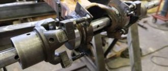
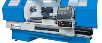
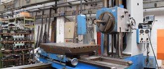
Horizontal boring machines
The main distinctive feature of a horizontal boring machine (Fig. 1) is the horizontal arrangement of the spindle. This type of machine is somewhat reminiscent of a conventional screw-cutting lathe. But there are several key differences in a horizontal boring machine. Firstly, the tailstock is missing. Instead of the tailstock, a movable rest is installed. Secondly, the faceplate with which the spindle is equipped has the ability to shift the cutter relative to the axis of rotation, which is not typical for a lathe. Thirdly, there is a table on which the part can be fixed.
Figure 1. Horizontal boring machine
Figure 1. Horizontal boring machine
Let's look at the main components and elements that make up a standard horizontal boring machine.
- Rear pillar. It is designed to attach a movable rest to it. Can be moved on the bed guides. Has a lever to lock the position.
- Lunette. This device is designed to hold the tail part of the workpiece if its length does not allow for reliable fastening to the table. Serves as an additional attachment point. The lunette can move in a vertical plane. Movement in the horizontal plane is carried out through the movement of the rear pillar.
- Front pillar. The main support on which the working part of the machine is mounted is the spindle head. On the front pillar there are vertical guides along which the headstock moves.
- Caliper. This element of a horizontal boring machine serves to feed the cutter to the surface of the workpiece. The support has the ability to move longitudinally in a horizontal plane along the axis of rotation.
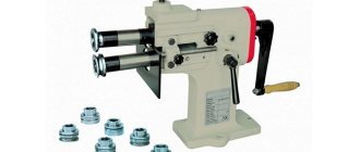
- Faceplate (Fig. 2). Unlike the standard faceplate of lathe group machines, it is used to secure the boring cutter in it. It has the ability to shift the cutter relative to the axis of rotation. This allows one tool to perform various boring operations.
- Spindle. Transmits rotational motion from the gearbox to the faceplate.
- Grandma. The working moving part of a horizontal boring machine. Inside the headstock there is an electric motor, gearbox and guides for axial movement of the caliper.
- Remote Control. Includes buttons for changing operating speed, reverse, automatic feed settings and emergency stop.
- Table. Serves for arranging and securing massive parts of small dimensions on it.
- Sled. Used to move the table.
- Bed. It is the base of the machine. On the bed there are two racks and a table. Sometimes the bed has the ability to adjust the installation level of the machine.
Figure 2. Boring machine faceplate.
Figure 2. Boring machine faceplate.
Today, horizontal boring machines that are equipped with a numerical control module are becoming increasingly common.
Workpiece processing
To process the parts you will need special equipment. In most cases, boring heads are used that are mounted in different devices. The heads have an all-metal shank holder; there is a groove on it that moves the slider cutter.
A device is also often used that allows for efficient and quick boring of molds (their dies). The workpiece is placed on the table and secured on both sides with bolts and clamps. The die cavity is processed using a square adjusting head. It is complemented by a regulator ring with a scale and a groove at the bottom. A slider with a cutter on a holder moves along it. Microscrews allow you to adjust the head. It is worth noting that heads are not used in all mechanisms of this type.
Boring equipment has a number of important advantages:
- Simplicity and versatility of technological equipment.
- Increased productivity.
- Reduced production cycle time.
- Rapid preparation of equipment for reorientation to the production of new parts.
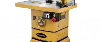
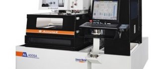
Jig boring machines
The main feature of jig boring machines (Fig. 3) is the high precision of processing parts.
Figure 3. Jig boring machine.
Figure 3. Jig boring machine.
Increased processing accuracy is achieved through the use of various high-precision mechanisms for calculating the coordinates along which the cutter moves. There are several main methods for calculating coordinates implemented on jig boring machines:
- inductive;
- mechanical;
- optical-mechanical;
- electronic.
The spindle on the machines of this subgroup is located vertically. But sometimes there are models with a horizontal spindle. The spindle head, in addition to changing the speed and direction of rotation, also carries out a working feed, increasing or decreasing the depth of penetration of the cutter into the part.
The table has two degrees of freedom. A part fixed on a table can move in the longitudinal and transverse directions. Moreover, the magnitude of these movements is controlled with high accuracy by the coordinate system.
Also, on jig boring machines, in addition to performing the entire range of operations characteristic of boring group machines, marking operations are performed.
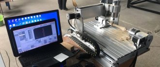
Design
The design of most modern CNC coordinate machines provides for servicing metal workpieces in 3 directions.
A specialized coordinate machine moves the cutter in the longitudinal (X) and transverse (Y) directions horizontally. Vertical movement (Z) is also provided. If the design provides for a special rotating device (processing cylindrical workpieces), horizontal movement can be replaced by rotating the steel raw material along the longitudinal axis. But in any case, the direction of movement of the cutter can only be determined by three independent coordinates.
The technical capabilities of the machine are optimal to move the cutters of the unit along fairly complex routes, simultaneously achieving simultaneous processing of various surfaces without changing the position of the workpiece.
In more advanced equipment, it was possible to modernize the coordinate system of a CNC machine, expanding their number to five. With a kind of “five-axis machining”, processing is carried out around 2 additional axes (the inclination of the tool changes). Setting up the equipment in this case is quite simple - to do this, just load the drawings into the internal memory, after which the CNC of the machine will independently determine the direction in which the movement is carried out. During operation of a CNC lathe, the angle of the tools changes due to the movement of the platform or the tilt of the spindles.
How are movements calculated?
Modern equipment uses two options for determining the position of movements - absolute and relative. The choice in favor of an absolute or relative CNC system is determined based on a number of factors. For example, exactly how dimensional chains are compiled in the drawings. It is common for certain machine control systems to choose between two options - in increments (relative method), or from a specific size base (absolute method).
Regardless of the number of points, a basic dimensional point must be present in the project. In CNC systems, it is convenient to use the base point as a zero point. But in the coordinate systems of CNC machines, you should always use absolute coordinates. Let's look at each system in more detail.
In a system using an absolute reference method, the CNC machine carries out milling operations starting from point P0, moving in a straight line, up to point P1. Using the relative system, lathes, compared to the previously considered option, move according to a different principle.
Multi-Axis Capabilities
A jig drilling machine allows you to produce complex parts:
- Lugs, holes of non-standard shape.
- Shaped surfaces, cabinet products.
- Gears, gears, impellers, rotors.
- Stiffening ribs can be worked out without difficulty.
- Holes in any projection at various angles, grooves, threads.
- All complex parts requiring curved processing.
- In one cycle, the entire surface of the workpiece can be processed.
Recently, vacuum tables have been widely used to hold the workpiece by suctioning air. Classic fasteners are no longer used, which reduces the time for removing and installing a new workpiece.