01.07.2020
Today, one of the most popular equipment options is under the spotlight. Let's look at what a dividing head for a milling machine is, the main features of the unit, what types there are, where it is used, how to operate it correctly, and so on. We will try to provide as many facts as possible so that you understand whether to install it to perform operations that are relevant to you or not.
Note that it can also be an important component of slotting, boring, drilling, planing equipment models. With its help, teeth, splines and grooves are cut, markings are made, the table is positioned, polyhedra and interdental cavities are machined, and rotation is coordinated with axial feed.
Now the definition: a simple or universal dividing head (UDG) is an equipment, that is, an additional machine tool, horizontally oriented, that serves to securely secure the workpiece, as well as to rotate it to the desired angle and/or divide it into the required number of parts equal to or not.
It expands the technological capabilities of the equipment and opens up new options and positions for processing parts. This determines the breadth of its modern use in mass and individual production, along with ease of installation, ease of commissioning, and reliable operation even under significant workload.
9) Set of replacement gears for guitar tuning:
25, 30, 35, 40, 50, 55, 60, 70, 80, 90, 100
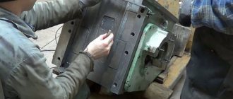
DIVISION HEAD DEVICE
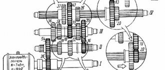
The universal dividing head (Fig. 1) consists of a worm pair and a number of gears. The housing 1 is mounted on the base 2 with its axles and is secured to it with cap clamps 3 to prevent rotation. A spindle 4 rotates in the bearings of the housing, on which a winding disk 5 is attached for direct counting of the rotation of the spindle, a worm wheel 6 and a locking wheel 7.
At the front end of the spindle, next to the front disk, chucks are installed to secure the workpieces.
Rotation of the workpiece at a certain angle is carried out by rotating the handle 8 with a spring lock 9, which fixes the handle relative to the dividing disk 10. From the handle 8, rotation through the roller 11 is transmitted by gears 12 and 13. The latter is connected to a shaft 14, made integral with the falling worm 15 The worm 15 is engaged with the worm wheel 6 by rotating the eccentric 16, which lifts the worm box 17.
Rice. 1 Dividing head device
Purpose of the dividing head
Dividing head
To form a part of the desired shape, it may need to be offset relative to the axis of the machine. This can be done using a dividing head. It can be either a separate part of the structure or its component.
The component is mounted on the equipment frame. It has various options for fixing the product, which depend on the type of attachment. The position is adjusted using several handles and a dial. The latter has holes that fix the position of the dividing component.
A similar tool may be needed to perform the following processes:
- milling grooves on the surface. This does not require great precision. It is important to control the depth and width of the workpiece;
- formation of edges on parts. This is true for non-standard nuts, tools, and shanks. The operation requires high precision;
- milling splines and grooves. This often requires significant displacements of the workpiece. Therefore, you should choose a dividing disk model with a minimum error rate.
To increase the speed of work, the part should not be constantly dismantled. Changing its position relative to the machine cutter occurs using the tool described above. Particularly difficult is the formation of helical grooves. This operation can only be performed using an accurate model.
Before purchasing a dividing head for a specific type of equipment, you must check its compatibility with the machine. Any independent alteration of the installation part may affect the quality of the product.
Can I do it myself?
The cost of the industrial design device in question is quite high, which is associated with the use of expensive materials and modern equipment in production. You can make a dividing head with your own hands, for which several points should be taken into account. To perform simple work, many people decide to make a turning mechanism with their own hands.
https://youtube.com/watch?v=tjVJyk-wEQg
To create the element in question, the following components are needed:
First you need a worm gearbox. Often it is taken from old technical equipment, and it can also be turned out independently. The worm gearbox is an important design element
Therefore, you need to pay attention to the quality of the design. The presence of even the slightest defects is unacceptable; you will also need a lathe chuck and a dial
The optimal diameter of the lathe chuck is 65 millimeters. They can be taken from a drawing board; In order to limit the processing progress, a locking screw is installed.
The design itself has many features that should be taken into account when making it yourself.
Scope of application and benefits
UDG is used in work on milling, jig boring, slotting, planing and drilling machines in operations where it is necessary to rotate the part by a certain, precise amount. The universal head is also used when carrying out marking and other work.
The universal head can be used for:
- cutting teeth;
- milling cavities between teeth;
- milling polyhedra;
- cutting grooves of cutting tools;
- precise positioning of the table;
- milling helical wheels;
- cutting splines;
- continuous rotation of the workpiece in accordance with its axial feed.
Division operations can be carried out in the chuck or in the centers of the machine, as well as when performing work on a spindle mandrel. The universal head design provides a wide range of possibilities:
- simple division;
- direct division;
- differentiated division without interval;
- milling of spirals, gears;
- processing of spiral hypoid grooves;
- setting the workpiece axis at a given angle relative to the machine.
In addition to significantly expanding the capabilities of metal-cutting equipment, universal dividing heads have other advantages:
- Possibility of processing workpieces of various sizes.
- Machining the surfaces of parts in the required position relative to the vertical plane.
- Easy to install and operate.
- Affordable price.
- Ease of use in single and mass production.
Calculation table of divisions
| Division parts | Number of revolutions | Counted holes | Total holes |
| 2 | 20 | — | — |
| 3 | 13 | 11 | 33 |
| 4 | 13 | 9 | 39 |
| 5 | 13 | 13 | 39 |
| 6 | 19 | — | — |
| 7 | 8 | — | — |
| 8 | 6 | 22 | 33 |
| 9 | 6 | 20 | 30 |
| 10 | 6 | 26 | 39 |
| 11 | 5 | 35 | 49 |
| 12 | 5 | 15 | 21 |
| 13 | 5 | — | — |
| 14 | 4 | 24 | 54 |
| 15 | 4 | — | — |
| 16 | 3 | 10 | 30 |
| 17 | 3 | 3 | 39 |
| 18 | 2 | 42 | 49 |
| 19 | 2 | 18 | 21 |
| 20 | 2 | 22 | 33 |
| 21 | 2 | 20 | 30 |
| 22 | 2 | 28 | 39 |
Part design and operating principle
In general, the boring head allows you to place either one or several cutting elements at once, however, it is recommended to resort to the optimal design with two radially spaced teeth, since this:
- Helps balance the radial component of the cutting force, which has a positive effect on accuracy;
- Significantly reduces the flow of vibration coming from the tool;
- In principle, it has a positive effect on the dynamics of the boring process.
At the same time, increasing the teeth will not have a positive effect on the work, since this entails a complication of the entire structure, plus, it makes it impossible for the operator at the machine to work at high speeds (fraught with the appearance of defects).
The boring head is fastened in the machine spindle (on the main executive body of the milling machine, that is, essentially, a rotating shaft that transmits force from the machine engine), while the part body is firmly fixed using a nut (or a group of nuts, or using micrometric screws).
The main components of the design of such equipment are the following parts:
- The hub is the central part of the equipment with a small hole that is necessary for mounting on the torque element. The mounting location for this part is the shank, described below, fastening is carried out through four screws, two of which additionally connect the quill;
- A quill that secures the cutting element;
- A slider, which is a moving part inside the quill along two guides using a lead screw. With its help, you can adjust the position of the cutting component relative to the center of the existing hole;
- Tapered shank that precisely fits the front spindle bore. Through this part, rotation is transmitted to the tool.
The process of working with the boring head is as follows:
- The shank is inserted into the spindle (into the cone-shaped hole), after which it is tightened with a screw to ensure tightness;
- After this, the part must be firmly installed in a vice or some other similar equipment;
- If it is necessary to bore a hole of less than 40 mm, then the position of the cutting component is adjusted only using a slider;
- In the case of boring a hole with a larger diameter (up to 85 mm), you should first repeat what was described in the paragraph above, after which the slider should be moved to its initial position, loosen the fastening screws and move the quill into the hub until it stops.
Below is a video of preparing the boring head for work and its direct use.
Disc cutters
The most convenient for cutting deep grooves of different widths are three-sided disk ones. A tool equipped with adjustable plates is more often used as a groove tool. The feature of changing the angle of the cutting elements allows you to cut a groove or groove.
Disc grooves are designed to create shallow grooves. Their teeth are located on a cylindrical body. An angle widening towards the outside helps reduce friction when cutting grooves or grooves. The peculiarity of this cutter is that it is narrower at the hub than in outer diameter.
2 and 3 sided have teeth on the end sides. Their lateral cutting edges are auxiliary, the main ones are located on the cylinder itself. Teeth located around a circle can have positive and negative angle inclination values. Negative corners at the end are cut off.
If you find an error, please select a piece of text and press Ctrl+Enter
Milling cutters are bladed metal-cutting tools, the working stroke of which represents a rotational cutting movement with a simultaneous feed movement in a direction that does not coincide with the axis of rotation. A distinctive feature of this tool is the inability to change the radius of the trajectory of the main cutting movement (GOST 25751-83).
Milling is one of the most popular methods of processing metal products. With a linear feed movement and the use of special cutting elements, cylindrical parts with a smooth surface are processed, as well as models with grooves and grooves. To carry out this kind of work, you need to buy a metal cutter that guarantees high-quality processing of various shaped elements, without reducing their strength.
Professionally manufactured cutters are distinguished by versatility and the ability to effectively process products from a wide range of materials:
- aluminum;
- various types of steel;
- alloys that differ in the percentage of non-ferrous and ferrous metals;
- copper, etc.
Each of the listed materials is characterized by an individual level of hardness, density, etc. To take these characteristics into account, a variety of metal cutters are available on the specialized market. They differ in their type of design, size, frequency and direction of teeth, type of installation and a number of other characteristics.
Metal cutters are characterized by maximum blade strength and a precisely set, constant trajectory of movement. The feed is carried out in a direction other than axial rotation. These features of the cutting surface fully comply with the requirements of GOST 25751-83.