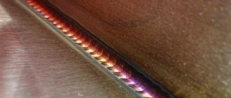
Poor connections can cause accidents. Pipelines, parts subject to dynamic loads, and welds exposed to fracture must not contain slag, cavities, or lack of fusion. Methods for flaw detection of welds belong to non-destructive diagnostics. They are used to identify internal, invisible defects in the metal - discontinuities that reduce the strength of the connection.
10 diagnostic methods have been developed, all of them have advantages, disadvantages and limitations. Flaw detection of welded seams checks the quality of welders’ work and identifies technology violations. They use metal diagnostic methods for incoming, intermediate and acceptance inspection.
The essence of the ultrasonic method
The principle of ultrasonic flaw detection was first proposed in 1928: Soviet scientist Sergei Sokolov showed how to detect damage to metal and other materials through variations in ultrasonic energy. Sokolov invented the first flaw detector, in which he used ultrasonic vibrations to determine internal defects, cracks, foreign inclusions and the structure of materials. Subsequently, this experience was picked up by scientists from other countries, and the method spread, becoming mandatory for many industries.
The ultrasonic method of metal testing is based on the physical law of the invariability of the trajectory of sound waves, provided the medium is homogeneous. The essence is to identify damage to the material through the radiation and acceptance of ultrasonic vibrations when reflected from a defect, analyzing the amplitude of vibrations, return time, shape and other parameters.
For analysis, high-frequency oscillations (over 20 kHz) are created in the material using a flaw detector and transducers with a piezoelectric element. If there are no flaws, the vibrations do not encounter obstacles and are not reflected. If there are inhomogeneities (for example, cracks, voids or other inclusions), the receiver will register reflection signals from them.
The wave propagation time indicates the depth of the defect, and the pulse reflection amplitude indicates the size of the inhomogeneity.
Procedure for carrying out ultrasonic testing
Let us consider the procedure for carrying out ultrasonic flaw detection using the example of weld inspection. Before inspection, all work on this equipment must be completed.
Before starting, it is necessary to clean the area along the weld seam to a distance D, which is calculated by the formula D = Lmax + 30 mm; where L is the length of the probe’s movement zone (usually 120 - 150 mm).
Cleaning for rental does not need to be done, but only metal splashes and corrosion with a depth of more than 1 mm can be removed. All nicks, dents and irregularities must be removed. Cleaning is carried out using metal brushes, files, and also using a grinding machine using abrasive wheels.
The roughness of the prepared surface should not be higher than Rz40 and the temperature at which the control will be carried out should be in the range from minus 30 to plus 30 degrees.
Next, to create acoustic contact, a contact fluid (glycerin, mineral transmission and machine oils, specialized fluids and gels) is applied to the surface.
Afterwards, the flaw detector is adjusted on standard samples SO-2 and SO-3, and the sensitivity is set using an artificially made reflector (defect) on a standard enterprise sample - SOP. The designs of SOPs with artificial reflectors are given below.
Standard sample (SOP) with a notch, this is used for setting up a flaw detector with a combined probe
SOP “punt” - in which a hole with a flat bottom is made for setting up a chord-type probe.
The serviceability of PEPs is checked using standard samples of the enterprise SO-2 and SO-3. CO-3 is used to determine the exit point and boom.
Using CO-2, the insertion angle is determined.
The enterprise standard sample (SOP) shows the maximum permissible defect for a given test object at a given thickness. It is used to adjust the sensitivity of the flaw detector. First, the signal received by a single reflected beam is adjusted, and then the signal received during control by a direct beam is adjusted. The most commonly used methods of control are direct and single-reflected beams.
Next, the object itself is sounded. The transducer is placed perpendicular to the weld seam and smoothly moved, moving away and bringing it closer, making a kind of reciprocating movement. In the process of making movements, the transducer is turned at an angle from 10 to 15 degrees to the right to the left. The movement step should be no more than 5-6 mm.
During the scanning process, the flaw detector monitors the received signals on the display of the flaw detector and, in case of defects, marks the location on the product with a marker or chalk.
Below you can see the sound diagrams for various welding joints.
Properties of ultrasound and the importance of the condition of the surface being diagnosed
Ultrasound tests the material without destroying its structure.
Ultrasonic testing is one of the main ones in flaw detection.
During flaw detection, the vibration length is taken into account - it is directly proportional to the resolution and sensitivity and inversely proportional to the vibration energy. The optimal indicator is 0.5-10 MHz.
The correctness of the measurement results depends on the condition of the surface being diagnosed. Free access to all measured areas is necessary for the free passage of ultrasound waves through the object. There should be no foreign bodies on the surface (oil, grease, dirt, lint, metal splashes, welding flux, etc.)
To prepare the surface you need:
- Clean the paintwork and rust at a distance of 5-7 cm.
- Treat the material with transformer, turbine or machine oil.
- Eliminate air gaps by applying coupling fluid (you can use water, oil or glycerin)
- Create a surface roughness greater than or equal to class 5 (using a piezoelectric transducer).
If there is a foreign coating on the surface that cannot be removed, complete adhesion to the material must be ensured.
What is ultrasonic testing of welding joints
Ultrasonic testing (UT) or ultrasonic flaw detection is a non-destructive testing method. Parts and materials exposed to it are not damaged. It is used in many areas and sectors in industry, medicine, etc.
This method is actively used in the inspection of welds such as butt, corner, overlap and T-joints with structural penetration (these are those seams in which, after welding, there will be no unwelded area left inside). The figure shows, as an example, a T-weld with structural penetration T8 according to GOST 5264)
The technique is based on the use of ultrasound (a sound wave with a frequency above the hearing threshold of more than 20 kHz; frequencies from 180 kHz - 10 MHz, and sometimes up to 100 MHz, are used for control).
Ultrasound testing uses 2 basic principles:
- Change in amplitude of the reflected signal (defects are detected).
- Measuring the time it takes a wave to travel through a product (thickness is determined)
Based on these 2 principles, inspection of welded joints, metal during incoming inspection, and various equipment that has been in use for a long time is carried out and its residual life needs to be assessed.
Sources of ultrasonic waves
During analysis, ultrasonic vibrations are created in an object in several ways. Most often using the piezoelectric effect. The transducer creates ultrasonic radiation, which further converts electrical vibrations into acoustic ones. When passing through the measured medium, these oscillations appear on the receiving piezoelectric plate of the transducer, and then become electrical again. This is recorded by measuring circuits. In this case, piezoelectric plates can act as only a receiver or only an emitter, and also combine the functions of both.
The piezoelectric element is a source of ultrasonic waves.
Critical angles
When performing ultrasonic testing, the operator needs to select the type of transducer, calibrate and configure the device for the expected defects of the object. Critical angles of incidence (longitudinal and transverse) must be taken into account when ultrasound passes through solid surfaces of materials.
The first critical angle is the smallest angle of incidence of the longitudinal wave at which the refracted ray does not cross the boundary of the second solid medium. For example, for the plexiglass-steel boundary it is 27.5º.
We recommend reading Rules for welding work
The second critical angle is considered to be the smallest angle of incidence of the longitudinal beam at which refraction does not penetrate through the boundary into the second solid medium and internal damage is not detected. For plexiglass-steel it is 57.5º.
The third critical angle is the smallest angle of incidence of the transverse beam at which there is no reflected longitudinal wave. The beam travels along the surface of the object without recognizing defects inside it. To cross the steel-air boundary, the angle is 33.3º.
Ultrasonic flaw detection methods
There are 4 main methods:
- Shadowy. Two transducers are used: the first (emitter) creates acoustic vibrations at the boundary of two media, the second (receiver) records them. A prerequisite for this is the location of the second transducer exactly in the direction of the wave created by the emitter. When encountering damage, the vibrations disappear. The identified blind area indicates the location of damage on the material.
- Mirror-shadow. It is close in principle to the shadow one, but involves the location of the transducers on one surface of the welding joint. In this case, the flux reflected from the second surface is recorded. Damage in the material is determined by the loss of reflected vibrations.
- Echo-mirror. 2 converters are on one side of the connection. The created ultrasonic vibrations are recorded at the moment of reflection from an obstacle.
- Pulse echo. It assumes the presence of one converter acting as both a source and a receiver. An acoustic wave is directed at the welded joint, recording the reflection from the foreign body.
Methods and schemes for flaw detection control.
Comparison and selection of the best
The choice of method depends on the characteristics of the material being tested, the conditions of conduct (stationary tests or analysis during operation) and is selected individually.
Results Evaluation Options
Interpretation of the results obtained by ultrasonic testing methods when sounding welded joints is one of the important stages of the work.
When a defect is detected, measure:
- The depth of the defect.
- Length.
- Distance between defects (if there are several of them).
- Maximum amplitude from the signal.
- Total length of defects.
The results are recorded in the control log, as well as in the conclusion or protocol. The control log indicates:
- The number of the welding joint according to the form and its type;
- length of the controlled area;
- SOP No.;
- operating frequency and input angle;
- control results;
- areas that could not be controlled (in the absence of access);
- date of inspection and signature of flaw detectors.
Defects detected during inspection are described using alphanumeric designations. To indicate defects, GOST 14782 should be used.
Ultrasound diagnostic capabilities
The ultrasound method allows:
- Fix defects inside (under the surface) of the material without violating its integrity.
- Find areas of corrosion damage.
- Identify extraneous inclusions and heterogeneities in the structure.
- Determine the location and size of flaws.
- Assess the condition of connections in the material.
The analysis is used in industry:
- Checking rods (plastic and metal), pipes for porosity, cracks and voids.
- Ultrasonic inspection of welds with a high-frequency sensor.
- Detection of voids in elements, measurement of wall thickness of parts.
- When working with composites and fiberglass, detect damage or delamination upon impact.
- Checking adhesive connections after soldering (if there is access to the surface).
Flaw detection provides ultrasonic quality control of welded joints.
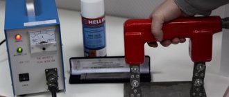
Magnetic inspection of welds
Magnetic flaw detection methods are based on the creation of a magnetic field that penetrates the body of the weld. For this purpose, a special apparatus is used, the operating principle of which is based on the phenomena of electromagnetism.
There are two ways to determine a defect within a connection.
- Using ferromagnetic powder, usually iron. It can be used both dry and wet. In the second case, iron powder is mixed with oil or kerosene. It is sprinkled on the seam, and a magnet is installed on the other side. In places where there are defects, powder will collect.
- Using ferromagnetic tape. It is laid on the seam, and the device is installed on the other side. All defects that appear at the junction of two metal workpieces will be displayed on this film.
This option for flaw detection of welded joints can be used to control only ferromagnetic joints. Non-ferrous metals, steels with chrome-nickel coating and others are not controlled in this way.
For which objects is it applicable?
The ultrasonic testing method is used in oil and gas production, in large industries, in nuclear energy, etc. In metallurgy, for example, ultrasonic flaw detection is used in the processing of castings and forgings. In the aircraft industry - for diagnosing polymers and composites for the presence of cracks, leaks, etc.
Ultrasonic flaw detection is used in oil and gas production.
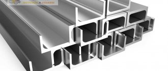
In metallurgy, sheet steel is subjected to control, which is widely used in the construction of road and railway bridges, in civil and industrial construction of buildings and structures that require increased strength and reliability.
In foundry production, the method allows one to see voids, porosity, inclusions and cracks in the structure of ferrous and non-ferrous metals. It is also possible to measure the thickness of a product, such as complex shaped hollow castings, without compromising its integrity in automotive engine manufacturing.
In construction, to assess the condition of concrete structures, it is important to check the actual strength against design requirements. Factors influencing the performance properties of concrete and reinforcement are being checked. The ultrasound method makes it possible to work not only in laboratory conditions, but also on a construction site.
When inspecting welded joints and surfacing of equipment and pipelines of nuclear power plants, the ultrasonic method is the only solution.
This is due to the use of stainless, austenitic, coarse-grained steels in the structures of nuclear reactors and tanks.
We recommend reading: Welding technology for internal combustion engine blocks
For pipes
Flaw detection is used on main and process pipelines. Thanks to this procedure, small defects and cracks in pipes that appear naturally over time do not develop into problems that threaten safety and require the main systems to be taken out of service.
The method of ultrasonic flaw detection of welds is used for pipelines.
The use of ultrasonic flaw detection makes it possible to detect the following damage to pipes:
- low level of tightness (or lack thereof);
- loss of control over tension;
- deformation and depressurization of welded joints.
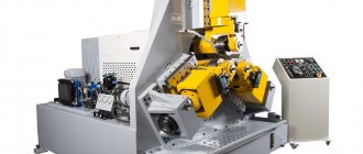
For pile structures and rails
Diagnostics of welded joints is indispensable for identifying cracks in the base or head of rails and for detecting joint defects. The method can be used stationary (at a rail welding plant) or in the field. For ultrasonic testing of piles and welds, flaw detectors with special characteristics are used - high resistance to humidity, operating temperature up to +35ºС (without moisture formation). At the same time, measuring instruments require constant protection from dust.
Ultrasonic flaw detection remains relevant for identifying cracks on rails.
Diagnostics of piles is a necessary stage in construction, at which the strength of the concrete base and the density of pouring bored piles are checked and recorded. During testing, the receiver with the emitter is installed at the lowest point of the pile, the received signals are recorded, then the sensor is moved to the next point.
The ultrasonic method of monitoring welds shows flaws with high accuracy and does not violate the integrity of load-bearing structures.
For other details
The material is subjected to flaw detection during technical examinations and examinations; the metal is checked at the entrance and exit. The method is used to check the industrial safety of pressure vessels, pump housings, fittings, heat exchangers, furnaces, etc.
METHODS AND TECHNICAL MEANS FOR DEFECTOSCOPY OF MATERIAL PARTS OF MACHINES AND ELEMENTS OF METAL STRUCTURES
Lecture No. 10
Flaw detection is a field of knowledge that covers the theory, methods and technical means of determining defects in the material of controlled objects, in particular in the material of machine parts and metal structure elements.
Flaw detection is an integral part of diagnosing the technical condition of equipment and its components. Work related to the identification of defects in the material of equipment elements is combined with repairs and maintenance or carried out independently during the period of technical inspection.
To identify hidden defects in structural materials, various non-destructive testing (flaw detection) methods are used.
It is known that defects in a metal cause changes in its physical characteristics: density, electrical conductivity, magnetic permeability, elastic and other properties. The study of these characteristics and the detection of defects with their help is the physical essence of non-destructive testing methods. These methods are based on the use of penetrating radiation of x-rays and gamma rays, magnetic and electromagnetic fields, vibrations, optical spectra, capillarity phenomena and others.
According to GOST 18353, non-destructive testing methods are classified by type: acoustic, magnetic, optical, penetrating substances, radiation, radio wave, thermal, electrical, electromagnetic. Each type is a conditional group of methods united by common physical characteristics.
The choice of the type of flaw detection depends on the material, design and size of the parts, the nature of the detected defects and the flaw detection conditions (in workshops or on a machine). The main qualitative indicators of flaw detection methods are sensitivity, resolution, and reliability of results. Sensitivity
– smallest sizes of detected defects;
resolution
- the smallest distance between two adjacent minimum detectable defects, measured in units of length or the number of lines per 1 mm (mm-1).
The reliability of the results
is the probability of missing defects or rejecting suitable parts.
Acoustic methods
are based on recording the parameters of elastic vibrations excited in the object under study. These methods are widely used to control the thickness of parts, imperfections (cracks, porosity, cavities, etc.) and physical and mechanical properties (grain size, intergranular corrosion, depth of the hardened layer, etc.) of the material. The control is performed based on an analysis of the nature of the propagation of sound waves in the material of the part (amplitude, phase, speed, angle of refraction, resonance phenomena). The method is suitable for parts whose material is capable of elastically resisting shear deformations (metals, porcelain, plexiglass, some plastics).
Depending on the frequency, acoustic waves are divided into infrared - with a frequency of up to 20 Hz, sound (from 20 to 2∙104 Hz), ultrasonic (from 2∙104 to 109 Hz) and hypersonic (over 109 Hz). Ultrasonic flaw detectors operate with ultrasonic signals from 0.5 to 10 MHz.
The main disadvantages of ultrasonic methods include the need for a sufficiently high cleanliness of the surface of parts and the significant dependence of the quality of control on the qualifications of the flaw detector operator.
Magnetic methods
are based on registration of magnetic scattering fields over defects or magnetic properties of the controlled object. They are used to detect surface and subsurface defects in parts of various shapes made of ferromagnetic materials.
In the magnetic particle method, magnetic powders (dry method) or their suspensions (wet method) are used to detect magnetic leakage flux. The developing material is applied to the surface of the product. Under the influence of a magnetic scattering field, powder particles are concentrated near the defect. The shape of its clusters corresponds to the outline of the defect.
The essence of the magnetographic method is to magnetize the product while simultaneously recording a magnetic field on a magnetic tape that covers the part, and then deciphering the information received.
The magnetic lines of force of the resulting field are directed along helical lines to the surface of the product, which makes it possible to detect defects of different directions.
After inspection, all parts, except defective ones, are demagnetized. Restoring non-demagnetized parts by mechanical processing can lead to damage to the working surfaces due to the attraction of chips. You should not demagnetize parts that are subjected to heating during restoration by welding, surfacing and other methods up to a temperature of 600...700°C.
The degree of demagnetization is controlled by showering the parts with steel powder. For well-demagnetized parts, the powder should not be retained on the surface. For the same purposes, devices equipped with fluxgate pole detectors are used.
To inspect parts using the magnetic particle method, stationary, portable and mobile flaw detectors are commercially produced. The latter include: current sources, devices for supplying current, magnetizing parts and for applying magnetic powder or suspension, electrical measuring equipment. Stationary devices are characterized by high power and performance. All types of magnetization can be carried out on them.
Eddy current methods
are based on the analysis of the interaction of an external electromagnetic field with the electromagnetic field of eddy currents induced by an exciting coil in an electrically conductive object.
Eddy current methods make it possible to detect surface defects, including those under a layer of metal and non-metallic coatings, control the dimensions of coatings and parts (diameters of balls, pipes, wires, sheet thickness, etc.), determine the physical and mechanical properties of materials (hardness, structure, depth nitriding, etc.), measure vibrations and movements of parts during machine operation.
Flaw detection of parts using radiation methods
is based on recording the weakening of the intensity of radioactive radiation when passing through a controlled object. The most commonly used are X-ray and γ-inspection of parts and welds. The industry produces both mobile X-ray machines for work in workshops and portable ones for work in the field. Registration of radiation monitoring results is carried out visually (images on screens, including stereoscopic images), in the form of electrical signals, and recording on photographic film or plain paper (xeroradiography).
Advantages of radiation methods: high quality control, especially casting, welds, the state of closed cavities of machine elements; possibility of documentary confirmation of control results, which does not require additional decoding. Significant disadvantages are the complexity of the equipment and the organization of work related to ensuring the safe storage and use of radiation sources.
Radio wave methods
are based on recording changes in electromagnetic oscillations interacting with the controlled object. In practice, ultra-high frequency (microwave) methods have become widespread in the wavelength range from 1 to 100 mm. The interaction of radio waves with an object is assessed by the nature of absorption, diffraction, reflection, refraction of the wave, interference processes, and resonance effects. These methods are used to control the quality and geometric parameters of products made of plastics, fiberglass, thermal protective and thermal insulation materials, as well as to measure vibration.
Thermal methods.
In thermal methods, thermal energy propagating in an object, emitted by an object, and absorbed by an object is used as a diagnostic parameter. The temperature field of the surface of an object is a source of information about the characteristics of heat transfer processes, which, in turn, depend on the presence of internal and external defects, cooling of the object or part of it as a result of the outflow of a medium, etc.
The temperature field is monitored using thermometers, temperature indicators, pyrometers, radiometers, infrared microscopes, thermal imagers and other means.
Optical methods.
Optical non-destructive testing is based on the analysis of the interaction of optical radiation with an object. To obtain information, the phenomena of interference, diffraction, polarization, refraction, reflection, absorption, light scattering are used, as well as changes in the characteristics of the object of study itself as a result of the effects of photoconductivity, luminescence, photoelasticity and others.
Defects detected by optical methods include discontinuities, delaminations, pores, cracks, inclusions of foreign bodies, changes in the structure of materials, corrosion cavities, deviation of the geometric shape from a given one, as well as internal stresses in the material.
Visual entroscopy allows you to detect defects on the surfaces of an object. Entroscopes (video borescopes) for internal examination of hard-to-reach areas of an object include a fiberglass probe, with which the researcher can penetrate inside the object, and a screen for visual observation of the surface, as well as a printer for video recording of the examined surface of the object. The use of optical quantum generators (lasers) makes it possible to expand the boundaries of traditional optical control methods and create fundamentally new methods of optical control: holographic, acousto-optical.
Capillary method
flaw detection is based on the capillary penetration of indicator liquids into the cavities of surface and through discontinuities of an object, and registration of the resulting indicator traces visually or using a transducer (sensor).
Capillary methods are used to detect defects in parts of simple and complex shapes. These methods make it possible to detect defects of production, technological and operational origin: grinding cracks, thermal cracks, fatigue cracks, hairline cracks, sunsets, etc. Kerosene, colored, luminescent and radioactive liquids are used as penetrating substances, and the method of selectively filtered particles is also used.
When using colored liquids, the indicator pattern is colored, usually red, which stands out well against the white background of the developer - color flaw detection. When using luminescent liquids, the indicator pattern becomes clearly visible under the influence of ultraviolet rays - the luminescent method. Control of the nature of indicator patterns is carried out using a visual-optical method. In this case, the lines of the pattern are detected relatively easily, since they are tens of times wider and more contrasting than defects.
The simplest example of penetrant flaw detection is a kerosene test. The penetrating liquid is kerosene. The developer is chalk in the form of a dry powder or an aqueous suspension. Kerosene, seeping into the chalk layer, causes its darkening, which is detected in daylight.
The advantages of penetrant flaw detection are versatility in terms of shape and materials of parts, good clarity of results, simplicity and low cost of materials, high reliability and good sensitivity. In particular, the minimum dimensions of detectable cracks are: width 0.001 - 0.002 mm, depth 0.01 - 0.03 mm. Disadvantages: the ability to detect only surface defects, the long duration of the process (0.5 m - 1.5 hours) and labor intensity (the need for thorough cleaning), the toxicity of some penetrating liquids, insufficient reliability at subzero temperatures.
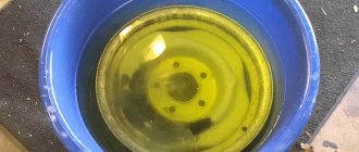
Cracks in parts can be detected using a kerosene test.
Kerosene has good wetting ability and penetrates deeply into through defects with a diameter of more than 0.1 mm. When controlling the quality of welds, kerosene is applied to one of the surfaces of the product, and an adsorbent coating (350...450 g of ground chalk suspension per 1 liter of water) is applied to the opposite surface. The presence of a through crack is determined by yellow stains of kerosene on the chalk coating.
Hydraulic and pneumatic testing methods are widely used to identify through pores and cracks.
With the hydraulic method, the internal cavity of the product is filled with working fluid (water), sealed, excess pressure is created with a pump and the part is kept for some time. The presence of a defect is determined visually by the appearance of water drops or sweating on the outer surface.
The pneumatic method for finding through defects is more sensitive than the hydraulic method, since air passes through the defect more easily than liquid. Compressed air is pumped into the internal cavity of the parts, and the outer surface is covered with a soap solution or the part is immersed in water. The presence of a defect is judged by the release of air bubbles. The air pressure pumped into the internal cavities depends on the design features of the parts and is usually equal to 0.05 - 0.1 MPa.
Non-destructive testing methods are not universal. Each of them can be used most effectively to detect specific defects. The choice of non-destructive testing method is determined by the specific requirements of practice and depends on the material, design of the object under study, the state of its surface, characteristics of defects to be detected, operating conditions of the object, control conditions and technical and economic indicators.
Surface and subsurface defects in ferromagnetic steels are detected by magnetizing the part and recording the stray field using magnetic methods. The same defects in products made from non-magnetic alloys, for example, heat-resistant, stainless, cannot be detected by magnetic methods. In this case, for example, the electromagnetic method is used. However, this method is also unsuitable for plastic products. In this case, the capillary method turns out to be effective. The ultrasonic method is ineffective in identifying internal defects in cast structures and alloys with a high degree of anisotropy. Such structures are monitored using X-rays or gamma rays.
Design (shape and dimensions) of parts
also determines your
boron control method. If almost all methods can be used to control an object of a simple shape, then the use of methods to control objects of a complex shape is limited. Objects with a large number of grooves, grooves, ledges, and geometric transitions are difficult to control using methods such as magnetic, ultrasonic, and radiation. Large objects are monitored in parts, identifying the most dangerous areas.
Surface condition
product, by which we mean its roughness and the presence of protective coatings and contaminants on it, significantly influences the choice of method and preparation of the surface for research. The rough rough surface excludes the use of capillary methods, the eddy current method, magnetic and ultrasonic methods in the contact version. Low roughness expands the capabilities of defetoscopy methods. Ultrasonic and capillary methods are used for surface roughness of no more than 2.5 microns, magnetic and eddy current methods - no more than 10 microns. Protective coatings do not allow the use of optical, magnetic and capillary methods. These methods can only be used after the coating has been removed. If such removal is impossible, radiation and ultrasound methods are used. Using the electromagnetic method, cracks are detected on parts with paint and other non-metallic coatings up to 0.5 mm thick and non-metallic non-magnetic coatings up to 0.2 mm thick.
Defects have different origins and differ in type, size, location, and orientation relative to the metal fiber. When choosing a control method, you should study the nature of possible defects. By location, defects can be internal, located at a depth of more than 1 mm, subsurface (at a depth of up to 1 mm) and superficial. To detect internal defects in steel products, radiation and ultrasonic methods are most often used. If the products have a relatively small thickness, and the defects to be detected are quite large, then it is better to use radiation methods. If the thickness of the product in the direction of transmission is more than 100-150 mm or it is necessary to detect internal defects in it in the form of cracks or thin delaminations, then it is not advisable to use radiation methods, since the rays do not penetrate to such a depth and their direction is perpendicular to the direction of the cracks. In this case, ultrasonic testing is most appropriate.
Lecture No. 10
Flaw detection is a field of knowledge that covers the theory, methods and technical means of determining defects in the material of controlled objects, in particular in the material of machine parts and metal structure elements.
Flaw detection is an integral part of diagnosing the technical condition of equipment and its components. Work related to the identification of defects in the material of equipment elements is combined with repairs and maintenance or carried out independently during the period of technical inspection.
To identify hidden defects in structural materials, various non-destructive testing (flaw detection) methods are used.
It is known that defects in a metal cause changes in its physical characteristics: density, electrical conductivity, magnetic permeability, elastic and other properties. The study of these characteristics and the detection of defects with their help is the physical essence of non-destructive testing methods. These methods are based on the use of penetrating radiation of x-rays and gamma rays, magnetic and electromagnetic fields, vibrations, optical spectra, capillarity phenomena and others.
According to GOST 18353, non-destructive testing methods are classified by type: acoustic, magnetic, optical, penetrating substances, radiation, radio wave, thermal, electrical, electromagnetic. Each type is a conditional group of methods united by common physical characteristics.
The choice of the type of flaw detection depends on the material, design and size of the parts, the nature of the detected defects and the flaw detection conditions (in workshops or on a machine). The main qualitative indicators of flaw detection methods are sensitivity, resolution, and reliability of results. Sensitivity
– smallest sizes of detected defects;
resolution
- the smallest distance between two adjacent minimum detectable defects, measured in units of length or the number of lines per 1 mm (mm-1).
The reliability of the results
is the probability of missing defects or rejecting suitable parts.
Acoustic methods
are based on recording the parameters of elastic vibrations excited in the object under study. These methods are widely used to control the thickness of parts, imperfections (cracks, porosity, cavities, etc.) and physical and mechanical properties (grain size, intergranular corrosion, depth of the hardened layer, etc.) of the material. The control is performed based on an analysis of the nature of the propagation of sound waves in the material of the part (amplitude, phase, speed, angle of refraction, resonance phenomena). The method is suitable for parts whose material is capable of elastically resisting shear deformations (metals, porcelain, plexiglass, some plastics).
Depending on the frequency, acoustic waves are divided into infrared - with a frequency of up to 20 Hz, sound (from 20 to 2∙104 Hz), ultrasonic (from 2∙104 to 109 Hz) and hypersonic (over 109 Hz). Ultrasonic flaw detectors operate with ultrasonic signals from 0.5 to 10 MHz.
The main disadvantages of ultrasonic methods include the need for a sufficiently high cleanliness of the surface of parts and the significant dependence of the quality of control on the qualifications of the flaw detector operator.
Magnetic methods
are based on registration of magnetic scattering fields over defects or magnetic properties of the controlled object. They are used to detect surface and subsurface defects in parts of various shapes made of ferromagnetic materials.
In the magnetic particle method, magnetic powders (dry method) or their suspensions (wet method) are used to detect magnetic leakage flux. The developing material is applied to the surface of the product. Under the influence of a magnetic scattering field, powder particles are concentrated near the defect. The shape of its clusters corresponds to the outline of the defect.
The essence of the magnetographic method is to magnetize the product while simultaneously recording a magnetic field on a magnetic tape that covers the part, and then deciphering the information received.
The magnetic lines of force of the resulting field are directed along helical lines to the surface of the product, which makes it possible to detect defects of different directions.
After inspection, all parts, except defective ones, are demagnetized. Restoring non-demagnetized parts by mechanical processing can lead to damage to the working surfaces due to the attraction of chips. You should not demagnetize parts that are subjected to heating during restoration by welding, surfacing and other methods up to a temperature of 600...700°C.
The degree of demagnetization is controlled by showering the parts with steel powder. For well-demagnetized parts, the powder should not be retained on the surface. For the same purposes, devices equipped with fluxgate pole detectors are used.
To inspect parts using the magnetic particle method, stationary, portable and mobile flaw detectors are commercially produced. The latter include: current sources, devices for supplying current, magnetizing parts and for applying magnetic powder or suspension, electrical measuring equipment. Stationary devices are characterized by high power and performance. All types of magnetization can be carried out on them.
Eddy current methods
are based on the analysis of the interaction of an external electromagnetic field with the electromagnetic field of eddy currents induced by an exciting coil in an electrically conductive object.
Eddy current methods make it possible to detect surface defects, including those under a layer of metal and non-metallic coatings, control the dimensions of coatings and parts (diameters of balls, pipes, wires, sheet thickness, etc.), determine the physical and mechanical properties of materials (hardness, structure, depth nitriding, etc.), measure vibrations and movements of parts during machine operation.
Flaw detection of parts using radiation methods
is based on recording the weakening of the intensity of radioactive radiation when passing through a controlled object. The most commonly used are X-ray and γ-inspection of parts and welds. The industry produces both mobile X-ray machines for work in workshops and portable ones for work in the field. Registration of radiation monitoring results is carried out visually (images on screens, including stereoscopic images), in the form of electrical signals, and recording on photographic film or plain paper (xeroradiography).
Advantages of radiation methods: high quality control, especially casting, welds, the state of closed cavities of machine elements; possibility of documentary confirmation of control results, which does not require additional decoding. Significant disadvantages are the complexity of the equipment and the organization of work related to ensuring the safe storage and use of radiation sources.
Radio wave methods
are based on recording changes in electromagnetic oscillations interacting with the controlled object. In practice, ultra-high frequency (microwave) methods have become widespread in the wavelength range from 1 to 100 mm. The interaction of radio waves with an object is assessed by the nature of absorption, diffraction, reflection, refraction of the wave, interference processes, and resonance effects. These methods are used to control the quality and geometric parameters of products made of plastics, fiberglass, thermal protective and thermal insulation materials, as well as to measure vibration.
Thermal methods.
In thermal methods, thermal energy propagating in an object, emitted by an object, and absorbed by an object is used as a diagnostic parameter. The temperature field of the surface of an object is a source of information about the characteristics of heat transfer processes, which, in turn, depend on the presence of internal and external defects, cooling of the object or part of it as a result of the outflow of a medium, etc.
The temperature field is monitored using thermometers, temperature indicators, pyrometers, radiometers, infrared microscopes, thermal imagers and other means.
Optical methods.
Optical non-destructive testing is based on the analysis of the interaction of optical radiation with an object. To obtain information, the phenomena of interference, diffraction, polarization, refraction, reflection, absorption, light scattering are used, as well as changes in the characteristics of the object of study itself as a result of the effects of photoconductivity, luminescence, photoelasticity and others.
Defects detected by optical methods include discontinuities, delaminations, pores, cracks, inclusions of foreign bodies, changes in the structure of materials, corrosion cavities, deviation of the geometric shape from a given one, as well as internal stresses in the material.
Visual entroscopy allows you to detect defects on the surfaces of an object. Entroscopes (video borescopes) for internal examination of hard-to-reach areas of an object include a fiberglass probe, with which the researcher can penetrate inside the object, and a screen for visual observation of the surface, as well as a printer for video recording of the examined surface of the object. The use of optical quantum generators (lasers) makes it possible to expand the boundaries of traditional optical control methods and create fundamentally new methods of optical control: holographic, acousto-optical.
Capillary method
flaw detection is based on the capillary penetration of indicator liquids into the cavities of surface and through discontinuities of an object, and registration of the resulting indicator traces visually or using a transducer (sensor).
Capillary methods are used to detect defects in parts of simple and complex shapes. These methods make it possible to detect defects of production, technological and operational origin: grinding cracks, thermal cracks, fatigue cracks, hairline cracks, sunsets, etc. Kerosene, colored, luminescent and radioactive liquids are used as penetrating substances, and the method of selectively filtered particles is also used.
When using colored liquids, the indicator pattern is colored, usually red, which stands out well against the white background of the developer - color flaw detection. When using luminescent liquids, the indicator pattern becomes clearly visible under the influence of ultraviolet rays - the luminescent method. Control of the nature of indicator patterns is carried out using a visual-optical method. In this case, the lines of the pattern are detected relatively easily, since they are tens of times wider and more contrasting than defects.
The simplest example of penetrant flaw detection is a kerosene test. The penetrating liquid is kerosene. The developer is chalk in the form of a dry powder or an aqueous suspension. Kerosene, seeping into the chalk layer, causes its darkening, which is detected in daylight.
The advantages of penetrant flaw detection are versatility in terms of shape and materials of parts, good clarity of results, simplicity and low cost of materials, high reliability and good sensitivity. In particular, the minimum dimensions of detectable cracks are: width 0.001 - 0.002 mm, depth 0.01 - 0.03 mm. Disadvantages: the ability to detect only surface defects, the long duration of the process (0.5 m - 1.5 hours) and labor intensity (the need for thorough cleaning), the toxicity of some penetrating liquids, insufficient reliability at subzero temperatures.
Cracks in parts can be detected using a kerosene test.
Kerosene has good wetting ability and penetrates deeply into through defects with a diameter of more than 0.1 mm. When controlling the quality of welds, kerosene is applied to one of the surfaces of the product, and an adsorbent coating (350...450 g of ground chalk suspension per 1 liter of water) is applied to the opposite surface. The presence of a through crack is determined by yellow stains of kerosene on the chalk coating.
Hydraulic and pneumatic testing methods are widely used to identify through pores and cracks.
With the hydraulic method, the internal cavity of the product is filled with working fluid (water), sealed, excess pressure is created with a pump and the part is kept for some time. The presence of a defect is determined visually by the appearance of water drops or sweating on the outer surface.
The pneumatic method for finding through defects is more sensitive than the hydraulic method, since air passes through the defect more easily than liquid. Compressed air is pumped into the internal cavity of the parts, and the outer surface is covered with a soap solution or the part is immersed in water. The presence of a defect is judged by the release of air bubbles. The air pressure pumped into the internal cavities depends on the design features of the parts and is usually equal to 0.05 - 0.1 MPa.
Non-destructive testing methods are not universal. Each of them can be used most effectively to detect specific defects. The choice of non-destructive testing method is determined by the specific requirements of practice and depends on the material, design of the object under study, the state of its surface, characteristics of defects to be detected, operating conditions of the object, control conditions and technical and economic indicators.
Surface and subsurface defects in ferromagnetic steels are detected by magnetizing the part and recording the stray field using magnetic methods. The same defects in products made from non-magnetic alloys, for example, heat-resistant, stainless, cannot be detected by magnetic methods. In this case, for example, the electromagnetic method is used. However, this method is also unsuitable for plastic products. In this case, the capillary method turns out to be effective. The ultrasonic method is ineffective in identifying internal defects in cast structures and alloys with a high degree of anisotropy. Such structures are monitored using X-rays or gamma rays.
Design (shape and dimensions) of parts
also determines your
boron control method. If almost all methods can be used to control an object of a simple shape, then the use of methods to control objects of a complex shape is limited. Objects with a large number of grooves, grooves, ledges, and geometric transitions are difficult to control using methods such as magnetic, ultrasonic, and radiation. Large objects are monitored in parts, identifying the most dangerous areas.
Surface condition
product, by which we mean its roughness and the presence of protective coatings and contaminants on it, significantly influences the choice of method and preparation of the surface for research. The rough rough surface excludes the use of capillary methods, the eddy current method, magnetic and ultrasonic methods in the contact version. Low roughness expands the capabilities of defetoscopy methods. Ultrasonic and capillary methods are used for surface roughness of no more than 2.5 microns, magnetic and eddy current methods - no more than 10 microns. Protective coatings do not allow the use of optical, magnetic and capillary methods. These methods can only be used after the coating has been removed. If such removal is impossible, radiation and ultrasound methods are used. Using the electromagnetic method, cracks are detected on parts with paint and other non-metallic coatings up to 0.5 mm thick and non-metallic non-magnetic coatings up to 0.2 mm thick.
Defects have different origins and differ in type, size, location, and orientation relative to the metal fiber. When choosing a control method, you should study the nature of possible defects. By location, defects can be internal, located at a depth of more than 1 mm, subsurface (at a depth of up to 1 mm) and superficial. To detect internal defects in steel products, radiation and ultrasonic methods are most often used. If the products have a relatively small thickness, and the defects to be detected are quite large, then it is better to use radiation methods. If the thickness of the product in the direction of transmission is more than 100-150 mm or it is necessary to detect internal defects in it in the form of cracks or thin delaminations, then it is not advisable to use radiation methods, since the rays do not penetrate to such a depth and their direction is perpendicular to the direction of the cracks. In this case, ultrasonic testing is most appropriate.
Pros and cons of ultrasound diagnostics
The main advantage of the method is that it relates to non-destructive testing. The object under study is not taken out of service, is not disassembled, does not take samples, and does not require other expensive actions.
Flaw detection allows you to prevent and promptly eliminate possible destruction of complex units and structures.
Other advantages of ultrasound:
- The method is available for working with metallic materials and non-metals.
- Accuracy in determining the position of the defect and assessing its size and shape.
- High research speed.
- Low cost of work.
- Health safety (less harm compared to x-ray work).
- Mobility, i.e. work in the field.
Ultrasonic flaw detection helps prevent possible damage.
Disadvantages of ultrasound diagnostics:
- Preliminary surface preparation is required.
- Rough materials, irregularly shaped parts, too small or thin parts cannot be inspected.
- It is impossible to work with cast iron and coarse-grained materials (due to high noise levels and low sound levels).
- Ultrasound may not detect damage oriented parallel to the sound beam.
GOST standards for ultrasonic testing
In total, there are about 30 regulatory documents that determine the procedure for conducting tests or examinations, the equipment used, etc.
We list some currently valid GOST standards for ultrasonic testing:
- GOST R 55724-2013 - Non-destructive testing. Welded connections. Ultrasonic methods.
- GOST 8.502-84 - Coating thickness gauges. Methods and means of verification.
- GOST R 55725-2013 - Non-destructive testing. Ultrasonic piezoelectric transducers. General technical requirements.
- GOST 28702-90 - Non-destructive testing. Ultrasonic thickness gauges. General technical requirements.
- GOST R 55809-2013 - Non-destructive testing. Ultrasonic flaw detectors. Methods for measuring basic parameters.
- GOST 27750-88 - Non-destructive testing. Restorative coatings. Methods for controlling the thickness of coatings.
- GOST 23858-79 — Welded butt and tee connections for reinforced concrete structures. Ultrasonic quality control methods. Acceptance rules.
- GOST 17624-87 - Concrete. Ultrasonic method for determining strength.
- GOST 24983-81 — Reinforced concrete pressure pipes. Ultrasonic method for monitoring and assessing crack resistance.
- GOST 26266-90 - Non-destructive testing. Ultrasonic transducers. General technical requirements.
- GOST 12.1.001-89 - Interstate standard. System of occupational safety standards. Ultrasound. General safety requirements.
- GOST R ISO 10332-99 — Seamless and welded steel pressure pipes (except for pipes manufactured by submerged arc welding). Ultrasonic method for monitoring continuity.
- GOST 24507-80 - Non-destructive testing. Forgings from ferrous and non-ferrous metals. Ultrasonic flaw detection methods.
- GOST ISO 4386-1-94 — Multilayer metal plain bearings. Non-destructive ultrasonic testing of the connection between the bearing metal layer and the base.
- GOST 21397-81 - Non-destructive testing. A set of standard samples for ultrasonic testing of semi-finished products and products made of aluminum alloys. Technical conditions.
Necessary equipment for flaw detection
For ultrasonic diagnostics, a flaw detector, a transducer with a built-in piezoelectric element (designed to emit and/or receive ultrasonic vibrations) and additional devices are used.
There are 3 types of ultrasonic transducers:
- Direct: emission of longitudinal waves at right angles to the surface being tested. They may have a ceramic piezoelectric element (made of barium titanate or lead zirconate titanate). Models from foreign brands use quartz - it has a relatively low sensitivity, which ensures uniform radiation and stable operation.
- Oblique (or prismatic): radiation of transverse waves into metal at an angle to the input surface. They carry out vertical scanning of parts and are used in cases where it is not possible to install the transducer directly on the surface of the material (for example, in corner joints, in structures with a complex profile).
- Separate-combined: the entry of longitudinal waves into the metal at an angle of 80-85º to the input surface. They have 2 piezo valves, one of which is a generator, and the second is a receiver. Suitable for working with rough materials and deformed surfaces.
A flaw detector is a device for detecting cracks in products.
The main component of the converter is a piezoelectric element in the form of a rectangular plate or disk. The thickness of the piezoelectric element is half the length of the emitted waves. In direct and inclined transducers, the piezoelectric element acts as an emitter and receiver of ultrasonic vibrations at the same time.
Diagram of the flaw detector
A flaw detector is an electronic unit for converting and amplifying echo signals when reflected from a defect, creating high-voltage probing pulses and visually displaying the amplitude-time characteristics of echo signals.
We recommend reading Methods for heating concrete using welding
A built-in switch is provided for directly connecting the amplifier to the radio pulse generator or disconnecting it from it (depending on the operating scheme). An automatic alarm detects a defect with a sound or light signal.
Flaw detector diagram.
The device may have additional blocks that expand the functions of the device and simplify the operator’s work. These include a temporary sensitivity control unit, which creates the same signal amplitude when detecting deformations of different sizes. This improves measurement accuracy.
Approximate cost of a flaw detector and other tools
The price range for flaw detectors is wide - from 90,000 to 2,500,000 rubles. The cost depends on the performance characteristics, brand and country of manufacture, year of manufacture. The price of stationary (for research in laboratories) and portable (for field conditions) models varies. The ability to connect to a PC, the amount of built-in memory and compatibility with several types of converters also affect the final cost. When choosing, you should start from the planned tasks and the expected scope of application.
Inspection of liquid penetrants (LP)
Liquid-liquid inspection improves visual inspection and is used to detect surface defects in non-porous metals. The first version of this technique was used in the late 1800s to detect cracks in locomotive parts and included heavy oil, kerosene and white chalk.
In the 1940s, fluorescent dyes were added to the liquid penetrant to increase the visibility of surface defects when used with ultraviolet light.
Liquid penetration testing requires cleaning the part so that the dye can get into defects. Penetrant is then applied, excess penetrant is removed, and then developer is applied. The inspector then views it under appropriate lighting. Once inspection is complete, the parts can be cleaned to remove the developer and dye.
Some of the benefits of liquid-liquid testing are: Metal flaw detection.
- Relatively simple and inexpensive
- Very portable
- High sensitivity to thin, dense tears
- Can be used with complex geometries
Some of the limitations of liquid penetration are as follows:
- The surface to be tested must be free of dirt, oil, grease, paint, rust and other contaminants.
- Cannot be used on porous samples and is difficult to use on very rough surfaces.
- Removal of all penetrating materials after testing is often required.
- Difficult to automate and record data.
How ultrasonic flaw detection specialists are trained
In accordance with current legislation, specialists working in the field of ultrasonic flaw detection undergo mandatory advanced training with subsequent certification.
It is carried out with the aim of determining sufficient theoretical and practical training of employees to perform one or several types of NDT, and the ability, based on the results obtained, to draw conclusions about the high-risk object under study in industry and construction.
Specialized research centers are engaged in training and certification of specialists. They create study programs lasting from 40 to 120 academic hours.
During this time they study:
- Types and methods of ultrasound diagnostics.
- Theoretical foundations of oscillations.
- Types and properties of waves.
- Rules for critical input angles.
- Sources of ultrasonic vibrations.
- Methods for flaw detection of welds and piles.
- Rules for acoustic flaw detection.
- Operating principle of ultrasonic testing devices.
Upon completion of training, employees pass exams, following which they receive an approved certificate indicating the qualification level - I, II or III. Level I specialists service equipment for non-destructive testing and draw up reports on the results of work, Level II specialists work at hazardous sites and give conclusions. Level III experts manage the process at all stages of its implementation; they require additional training using specially developed methods.
The acquired qualification must be confirmed every 3 years by passing the relevant exams.
Advantages and disadvantages
Advantages:
- low labor intensity of research, connections are controlled by one person within a few minutes;
- safety of monitoring, only radiation diagnostics assumes the influence of harmful factors;
- a variety of monitoring devices; mobile flaw detectors are produced for basic flaw detection methods;
- variety of controlled objects: flat, three-dimensional parts, pipes are checked;
- control of seams produced by any type of welding machine.
Flaws:
- each method has certain limitations on its use due to the identified shortcomings;
- the need to use special reagents and consumables;
- it is necessary to specially prepare the surfaces being examined;
- After diagnostics, controlled fragments must be additionally treated with anti-corrosion agents; when removing scale and oxide film, the protective properties of the metal deteriorate.
Briefly about other flaw detection methods
The capillary (liquid) method involves identifying defects on the surface of metals. Before diagnostics, parts are cleaned so that the dye enters unimpeded. A penetrant is applied to the material, excess is removed and a developer is introduced, which, under special lighting, detects surface damage. The liquid method is simple to perform, but requires preliminary thorough cleaning of the surface. It is impossible to automate this.
Eddy current testing shows damage inside the metal and on its surface using an electromagnetic field. Eddy currents flow differently in materials with and without defects. Eddy current diagnostics can be performed in seconds but are only applicable to metals. Such tests require highly qualified operators. The method is used in the aviation and nuclear industries.
Magnetic particle inspection detects damage on the surface or slightly below (working at the depth of the material is impossible). Dry or wet magnetic particles are applied to the material - they are attracted to the foreign body, indicating its shape and size. After completing the diagnostics, the part is demagnetized. This method is only suitable for working with ferromagnetic materials. The study requires complete demagnetization of the part, which makes it difficult to automate the process.
Visual inspection
Using an external examination, you can identify not only visible seam defects, but also invisible ones. For example, the unevenness of the seam in height and width indicates that there were interruptions in the arc during the welding process. And this is a guarantee that the seam inside has lack of penetration.
How to properly conduct an inspection.
- The seam is cleaned of scale, slag and drops of metal.
- Then it is treated with technical alcohol.
- After another treatment with a ten percent solution of nitric acid. It's called etching.
- The surface of the seam is clean and matte. The smallest cracks and pores are clearly visible on it.
Attention! Nitric acid is a material that corrodes metal. Therefore, after inspection, the metal weld must be treated with alcohol.
The magnifying glass has already been mentioned. Using this tool you can detect tiny flaws in the form of thin cracks less than a hair thick, burns, small cuts and others. In addition, using a magnifying glass you can check whether the crack is growing or not.
During inspection, you can also use calipers, templates, and a ruler. They measure the height and width of the seam, its even longitudinal location.