Metal marking
TO
category:
Marking
Metal marking
Next: Bench cutting, cutting and straightening
Marking is the operation of applying marks (lines) to a workpiece (forging, casting, rolled product, etc.) for its subsequent processing. Risks can be contour, control and auxiliary.
Contour marks separate the allowance metal from the metal of the finished part. In order for the contour marks to be better highlighted and preserved during transportation and processing of the workpiece, they are punched, that is, small conical depressions (cores) are applied along the marks.
During subsequent processing, the allowance is removed so that half the width of the contour mark and half of each punched recess (core) remain on the part. Contour marks are also used for installation and alignment of workpieces on the machine.
Auxiliary marks serve to measure dimensions when marking and installing a workpiece on the machine.
Control marks are applied next to the contour marks at a distance of 5-10 mm. Being parallel (or concentric) to the contour marks, these marks make it possible at any time to check both the correctness of installation and the correctness of processing (if for some reason the contour mark has disappeared).
Thus, marking consists of drawing on the workpiece the lines necessary for processing the part. Before marking, those parts of the workpieces on which the marks will be applied are painted so that the marks and cores can be easily found. For painting, chalk mixed with glue, diluted in water, is most often used. The treated surfaces of steel and cast iron workpieces are sometimes coated with a solution of copper sulfate in water; this leads (as a result of the reaction of copper sulfate with iron) to the formation of a thin layer of copper on the surface of the workpiece, along which marking marks are applied.
Marking is divided into planar and volumetric. Planar marking is made on sheet material on one side (in one plane); When marking in volume, marks are applied to two (or more) surfaces of the workpiece.
In modern mechanical engineering, they try to avoid marking whenever possible, since it requires highly qualified labor, and the processing accuracy of it is low. However, this is only possible in mass and large-scale production, where markings can be completely or largely eliminated through the use of special machines and devices that ensure correct alignment (installation) of the workpiece and guarantee that the dimensions of the parts are within the established tolerances. In single and small-scale production, the cost of manufacturing devices does not pay off, so parts are processed according to markings. The lack of accuracy of parts processed according to markings forces one to resort to individual fitting during assembly. For marking, the workpieces are placed on marking plates. The upper (working) plane of the slab, on which workpieces and marking tools are installed, and its side edges are precisely processed (planing).
Often, narrow and shallow mutually perpendicular grooves are cut along the upper plane of the slab so that squares with a side of 200 to 500 mm are formed. These grooves in many cases facilitate the installation of workpieces and fixtures on the plate. Slab sizes vary widely from 750 X 750 to 4000 X 6000 mm; larger slabs (for marking very large workpieces) are made up of several slabs and installed on the foundation.
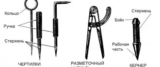
Scale rulers, surface planers, squares, compasses, center punches, etc. are used as marking tools.
A scale bar is used to measure dimensions; it is fixed on the square so that its end (zero line) touches the working surface of the slab.
A thicknesser is used to apply marks to the workpiece parallel to the working plane of the marking plate. When working with a thicknesser, the base is moved along the slab, and with a needle set according to the scale ruler to the height dimension, marks are applied.
A hand needle or scriber is used to mark lines along a ruler, square, or template.
Rice. 1. Scale ruler attached to a square
Rice. 2. Marking thicknesser
Rice. 3. Hand needle (scriber)
Rice. 4. Malka
The square is used to apply vertical marks with a scriber and to check the vertical position of any plane of the workpiece, as well as to construct right angles.
The mark and the goniometer are used to apply groove marks and control the installation of the workpiece on the marking plate. Setting the ruler to the desired angle is done using a protractor or protractor. After installation, the ruler is secured by turning the knob.
A marking compass is used for marking circles and arcs, as well as for marking dimensions taken from a scale ruler. In some cases, a caliper is also used to mark circles and arcs.
A center finder square is used to apply diametric marks on the ends of shafts and, accordingly, find centers at the ends. A center finder square consists of a square and a ruler attached to it, the working edge of which divides the corner of the square in half. To mark, a square is applied to the workpiece and a mark is applied along the ruler using a scriber. To find the center of the workpiece, apply a second mark after turning the square through a certain angle.
Rice. 5. Marking compass
Rice. 6. Square finder
Rice. 7. Kerner
The punch is used for applying core marks on marks or for marking the centers of holes.
Marking of metal products and blanks: tools, methods, rules | Construction Bulletin
In the production of metal products, the source material - castings, sheet and profile products - does not correspond in size and shape to the designer's drawing. To cut off excess metal, drill, stamp, weld, or otherwise process a workpiece, key points of the drawing are applied to it. Applying to these points and lines, the processing is carried out.
Basic concept and types of markup
As a rule, unique parts and products produced in small and ultra-small series are marked. For large-scale and mass production, workpieces are not marked; instead, special equipment and control programs are used.
What is markup
The operation of applying the dimensions and shape of a product to workpieces is called marking. The purpose of the operation is to designate the places where the part should be processed and the boundaries of these actions: drilling points, bend lines, weld lines, markings, etc.
Marking is done with points, which are called cores, and lines, which are called risks.
Marks are scratched into the metal surface with a sharp tool or applied with a marker. Cores are filled with a special tool - a center punch.
According to the method of execution, there are such types of markup as:
- Manual. It is made by mechanics.
- Mechanized. Performed using mechanization and automation tools.
Based on the application surface, they are distinguished
- Superficial. It is applied to the surface of the workpiece in one plane and is not associated with the lines and marking points applied to other planes.
- Spatial. It is carried out in a unified three-dimensional coordinate system.
Notes on straightening and marking for thin sheet metal
The choice between surface and spatial markings is determined, first of all, by the complexity of the spatial configuration of the part.
Markup requirements
Plumbing markings must meet the following requirements:
- accurately convey the key dimensions of the drawing;
- be clearly visible;
- not to be abraded or lubricated during mechanical and heat treatment operations;
- do not degrade the appearance of the finished product.
Marking of parts must be carried out with high-quality inventory tools and devices that are subject to periodic verification.
Applying marks
The standard regulates the procedure for drawing marking lines:
- horizontal;
- vertical;
- inclined;
- curvilinear.
Applying curved elements after straight ones provides another opportunity to check their accuracy. The arcs must close the straight lines, the interface must be smooth.
Direct marks are carried out with a well-sharpened scriber, without tearing off, in one step. At the same time, the scriber is tilted away from the ruler or square so as not to introduce distortions.
Parallel lines are drawn using a square and moving it along the reference ruler to the required distance.
If the workpiece already has holes, then a special tool, a center finder, is used to attach marking lines to them.
In order to mark inclined lines, use a marking protractor with a hinged ruler fixed at its zero point.
For particularly precise markings in plumbing, calipers are used. They allow you to measure distances and scratch marks with an accuracy of hundredths of a millimeter.
Marking marking lines
In order to more accurately carry out the risk, cores are placed at its beginning and end. This allows you to visually control the position of the ruler while drawing.
On long-distance risks, auxiliary cores are also placed through
every 5-15 cm.
Circle lines are marked at four points - the ends of perpendicular diameters.
If already treated surfaces are marked, then punching is used only at the beginning and end of the marks.
After finishing, the marks are extended to the side surfaces and the cores are placed on them.
Marking techniques
The following techniques are used in plumbing:
- According to the template. Used in case of small-scale production. The template is made from rolled metal, the entire batch is marked (or even processed) through once marked slots and holes in this sheet. For parts with complex shapes, several templates can be made for different planes.
- Following the example. The dimensions are transferred from the part - the sample. It is used in the manufacture of a new part to replace a broken one.
- Local. Used in the production of complex multi-component products and structures. Blanks are placed on a plane or in space in the order in which they enter the final product and are marked together.
- Pencil (or marker). Used for workpieces made of aluminum alloys so that the scriber does not destroy the passivated protective layer.
- Accurate. It is done using the same methods, but special precision measuring and marking tools are used.
The selection of techniques is carried out in accordance with design and technological instructions.
Marriage during marking
First of all, when marking, defects that were made at previous stages of production emerge. Products from procurement sites or workshops, as well as materials purchased from other enterprises, reveal:
- violation of dimensions
- shape distortion
- warping.
Such castings or rentals are not subject to further marking operations, but are returned to the department or organization that caused the defect to correct it.
At the marking stage itself, defects can be caused by the following factors:
- Inaccurate drawing. The mechanic, without hesitation, displays incorrect dimensions on the part, and during further processing, defective products come out.
- Inaccuracy or malfunction of instruments. All marking tools are subject to mandatory periodic verification by the metrological service of the enterprise or an authorized metrological center.
- Incorrect use of tools or marking accessories. There are known cases when instead of calibrated measuring pads, ordinary pads were used to set the level. In this case, erroneous application of angles and slopes is also possible.
- Inaccurate placement of the workpiece on the marking table or plaza. They lead to distortions when setting aside dimensions, violation of parallelism and coaxiality.
- Wrong choice of reference planes. It is also possible that some of the dimensions were applied from the base planes, and some from the rough surfaces of the workpiece.
Separately among the reasons for defects are the marker's errors. These include:
- Incorrectly read drawing. It is possible to apply a radius instead of a diameter and vice versa, inaccurate application of the centers of holes relative to the center marks, etc. If any difficulties arise, the mechanic must seek clarification from the foreman or foreman.
- Carelessness and inattention when punching and drawing lines.
The human factor, unfortunately, is the most common cause of marking defects.
Negligence can be committed by both the mechanic himself and his supervisors, who did not check the tool on time or issued inappropriate marking devices.
Typically, marking operations are entrusted to the most experienced and responsible workers, counting on the fact that they will not mechanically transfer dimensions from the drawing to the workpiece, but will treat the matter thoughtfully and promptly notice and eliminate the reasons for possible defects on their own or by contacting their managers.
How to level walls using plaster and drywall. Why does the electrode stick when welding? A house with an area of 1 square meter. Our happy future?
About metalworking
Processing of threaded surfaces is an operation that is carried out by removing a layer of material (chips) from the machined surface or without removing chips, i.e., plastic deformation. In the first case, we are talking about cutting a thread, and in the second, about rolling it. When assembling and repairing equipment and carrying out installation work, cutting or rolling threads is used manually or using hand-held mechanized tools.
A threaded rod that has a screw surface along its entire length or some part of it is called a screw , and a hole that has a screw surface is called a nut .
Thread elements (Fig. 1) are certain numerical parameters that characterize the thread.
Thread pitch P is the distance in millimeters between the tops of two adjacent threads, measured parallel to its axis.
Profile height H is the distance from the top of the thread to the base of the profile, measured in the direction perpendicular to the thread axis.
Rice. 1. Elements of triangular thread: α - profile angle; P - thread pitch; d is the outer diameter of the thread; d1 - internal thread diameter; d2 - average thread diameter; H - thread profile height
Rice. 3.24. Elements of triangular thread: a - profile angle; P - thread pitch; d is the outer diameter of the thread; d1 - internal thread diameter; d2 - average thread diameter; H - thread profile height
Profile angle α is the angle between the straight sections of the sides of the thread profile.
The outer diameter of the thread d is the largest diameter of the thread, which is measured along its tops in a direction perpendicular to the axis.
The internal diameter of a thread is the smallest distance between opposing thread roots, measured perpendicular to the axis.
The average thread diameter d2 is the diameter of a conditional circle drawn in the middle of the thread profile between the bottom of the recess and the top of the protrusion, measured in the direction perpendicular to the axis.
Tools and devices for cutting external and internal threads by hand. To cut external and internal threads manually, special thread-cutting tools (taps and dies) and devices are used to create the torque on the tool necessary to provide cutting forces during the processing process.
The tap (Fig. 2) consists of two parts: the working part, which ensures the cutting process, and the tail, at the end of which there is a square protrusion for installing the driver. The working part of the tap includes a cutting (taking) part, which ensures the removal of the main allowance for processing, and a calibrating part, which carries out the final processing of the thread. Taps for manual threading are made in the form of sets of two or three pieces (rough, medium and finishing), which are marked with circular marks on the tail part (one, two and three marks, respectively).
Rice. 2. Tap: 1 - thread (turn); 2 - square; 3— shank; 4 - groove
To create torque on the cutting tool (tap), special devices are used - wrenches of various designs.
The universal driver (Fig. 3) is a frame with two crackers - movable and fixed, forming a square hole and securing the tail part of the tap.
Rice. 3. Sliding knob: 1 - frame; 2 - coupling; 3 - handle; 4, 5 - movable and fixed cracker, respectively; a is the side of the square
A driver with switching cams (safety) (Fig. 4, a) allows you to protect the tap from breakage by disengaging the cams of the body and bushing when the force transmitted by the driver exceeds the permissible value.
The end driver (Fig. 4, b) is used when cutting threads in hard-to-reach places, as it allows you to work with one hand.
A ratchet driver (Fig. 4, c) is used for cutting threads in hard-to-reach places, when the driver can be turned at a small angle at a time.
Rice. 4. Gates: a - safety: 1 - body; 2 - bushing; 3 - spring; b - end; c - with ratchet
A die is a tool for cutting external threads, consisting of two parts: a tapping and a calibrating one. Their purpose is the same as that of the corresponding parts of the working part of the tap. When manually cutting threads, dies of various designs are used.
Round dies (Fig. 5, a) are a threaded ring with several grooves for forming cutting edges and removing chips. They are made whole and cut. Due to their springy properties, the dies allow you to adjust the average diameter of the thread being cut.
Square dies (Fig. 5, b) consist of two halves, which are secured in a special frame with handles - a clamp.
The clamp provides the ability to regulate the average diameter of the thread being cut.
Rice. 5. Threading dies: a - round: 1 - intake part; 2 - calibrating part; 3 - chip groove; b - square (sliding): 1 - die; 2 - die
To create a torque and ensure the cutting process when cutting external threads with dies, special devices are used - cranks (for round dies) and clamps (for split dies).
The driver for round dies (Fig. 6) is a round frame with a recess in which a round die is placed, held from turning by three locking screws. The fourth screw allows you to adjust the average diameter of the thread when using a split round die to cut it.
Rice. 6. Driver for round dies.
The die (see Fig. 5, b) is a square frame with protrusions into which the grooves of the die fit. One of the halves of the die can be moved using a screw, adjusting the average diameter of the thread being cut.
Hand-held power tools for cutting internal threads can be equipped with either a pneumatic or an electric drive.
A pneumatically driven thread cutter (Fig. 7) is designed for cutting small diameter threads. The pneumatic motor 1 rotates the spindle 4. When you press the handle 3 of the housing, threading occurs. When the pressure on handle 3 is released, the spindle 4 moves under the influence of the spring and its movement is reversed. In this case, the tap 5 is rapidly unscrewed from the hole in the workpiece 6. The tool is turned on by pressing the trigger 2.
Rice. 7. Thread cutter with pneumatic drive: 1 - pneumatic motor; 2 - trigger; 3 - handle; 4 - spindle; 5 - tap; 6 - blank
Electrically driven thread cutter (Fig. equipped with a built-in electric motor, reversing mechanism and gearbox.
Rice. 8. Electrically driven thread cutter
Preparing rods and holes for threading. During the thread cutting process, not only the removal of a layer of material from the surface of the workpiece occurs, but also plastic deformation of the machined surface, which is accompanied by the extrusion of part of the workpiece metal from the recesses of the thread turns to the tops. This phenomenon must be taken into account when determining the diameters of rods and holes for threading. Therefore, it is advisable to determine the dimensions of the workpieces using reference tables, in which they are given taking into account all the factors affecting the cutting process.
In practice, the diameter of the hole for the thread is chosen equal to its nominal size, reduced by the pitch. For example, when cutting an M10 thread, the hole diameter should be 10 - 1.5 = 8.5 mm.
When cutting external threads, the diameter of the rod should be 0.1 ... 0.2 mm less than the nominal diameter of the thread, depending on its size.
When processing external and internal threads, it is necessary to adhere to a number of rules.
- Manual threading must be done with the tap or die generously lubricated with machine oil.
- When cutting threads by hand, you should periodically cut off the resulting chips by moving the tap or die back 1/2 turn.
- After cutting the thread, it is necessary to control its quality: by external inspection (avoiding scuffing and torn threads) and with a thread gauge, the bore of which should be screwed on easily, by hand.
The rules for cutting external threads manually are as follows.
- Before cutting the thread, check the diameter of the rod, which should be 0.1 ... 0.2 mm less than the nominal thread size.
- Make a chamfer at the top of the rod so that it is concentric with the axis of the rod. In this case, its diameter should not be less than the internal diameter of the thread, and the angle of inclination relative to the axis of the rod should be 60°.
- The rod should be firmly secured in the vice, checking its perpendicularity to the clamping jaws using a square.
The rules for processing internal threads manually are as follows.
- Check that the diameter of the hole matches the size of the thread being cut.
- Check that the hole depth meets the drawing requirements when cutting blind threads.
- Using a square, check that the tap axis is perpendicular to the plane of the workpiece in the hole of which the thread is being cut.
- Use all taps in the set when cutting threads.
- Periodically clean blind holes from chips when cutting threads into them.
Threading on pipes is carried out using special tools - clamps and thread-cutting dies.
A die with sliding dies (Fig. 9) is a device most often used for cutting external threads on pipes. The die is equipped with a set of sliding dies for cutting threads with a diameter of 1/2…3/4; 1…11/4; and 11/2…2″. The clamp is mounted in such a way that four dies 5 moving in its body 1 can simultaneously approach the center or diverge from it. The movement of the dies is ensured by a special rotary device driven by a handle 4. The precise installation of the dies to the size of the thread being cut is carried out using a dial located on the body, and the installation movements are carried out by a worm gear 3. After installation, the position of the dies is fixed with a special device - a “pawl”. The cutting force is transmitted to the tool using handles 2.
Rice. 9. Jig for cutting pipe threads: 1 - body; 2 — handles; 3 - worm gear; 4 — handle for moving dies; 5 - dies
A round thread-cutting comb (Fig. 10, a) is used for cutting pipe threads on lathes and drilling machines. Combs are produced in sets of four. Thread cutting is carried out using a special self-opening screw-cutting head (Fig. 10, b).
Rice. 10. Round thread-cutting comb (a) and self-opening head for attaching it (b)
To facilitate the operation of the tool and improve the quality of threads obtained when cutting threads, COTS is used. Their choice depends on the material of the workpiece being processed. For example, an emulsion is used to cool steel workpieces (structural, tool and alloy steel). Kerosene should be used to cool cast iron and aluminum. Threading in copper, brass and bronze workpieces can be done without cooling.
What is metal marking?
Before you start processing a workpiece made of thin sheet metal, it should be marked , i.e. apply the contours of the future product to the workpiece.
Both slate and chalk lines are easily erased from the surface of metal, unlike wood. To prevent the marking lines from being erased, the metal surface can be pre-painted.
In this case, you can use a traditional marking tool - a pencil. But such a marking process will be lengthy and inconvenient.
There is the simplest and most widespread way - using a scriber.
Also, the following tools are used for marking:
Marking is one of the important and responsible operations. The quality of the future product depends on the accuracy of its implementation. If the workpiece is marked incorrectly, then in the future the cutting of the workpiece will not be according to size. This is especially important in the manufacture of volumetric products, where further work depends on the quality of correctly cut boundaries.
Before marking, the workpiece is straightened and cleaned of dust, dirt and traces of rust.
First, at a distance of approximately 5-8 mm from the edge of the workpiece, a base line is drawn along a ruler using a scriber. Further construction is carried out from the base line. The lines drawn during marking are called marks. Risks are main and auxiliary.
The main risks indicate the processing boundaries. From the auxiliary marks, the dimensions for drawing the main marks are set aside. It is not difficult to draw precise lines with a scriber.
When applying straight marks, the ruler or square must be pressed tightly against the workpiece so that there is no gap.
When making a mark, take the scriber like a pencil and, without interrupting the movement, draw a mark of the required length. The sharp end of the scriber should be pressed against the ruler, and the scriber should be tilted away from the ruler. And the angle of inclination should not be changed, otherwise the line will turn out to be crooked and not parallel to the ruler.
You cannot draw a line twice, because... It's hard to hit the same line a second time. As a result, the line may turn out to be double. If you are not satisfied with the quality of the applied mark, then you should clean it with sandpaper and carry out the operation again.
If it is necessary to mark several identical parts, then templates are used - sample plates with contours of the parts.
Before marking the template, you need to attach it to the workpiece and check whether the entire template fits on the sheet. To use material economically, they try to find such a position for the template on the sheet so that when subsequently cutting blanks from the sheet, there will be as little waste and trimmings as possible.
After which the template is pressed tightly to the plane of the workpiece by hand or a clamp and outlined with a scriber.
The centers of the holes are marked using a center punch. A core is placed in the marked center of the hole and a small hole (core) is made on the surface of the workpiece by lightly hitting the hammer with a hammer.
If it is necessary to mark a circle or rounding, then the leg of a marking compass, pre-set to the required radius of the circle, is installed in the resulting core, and the circle is outlined with the second leg.
- Before marking, it is necessary to check the serviceability of the marking tools.
- Perform marking only after editing the workpiece.
- Beware of sharp edges of sheet metal and wire.
- Do not put the scriber and marking compass in the pocket of your work coat.
- Pass the scribe only with the ring facing away from you.
Types and methods of processing various materials
Technologies for manual and machine processing of wood and wood materials. Technologies for manual and machine processing of metals and artificial materials
Page 3
Types and methods of processing various materials Areas of production. Professional career and education. Technologies of research and experimental activities. Housekeeping. Repair and construction work. Home Economics Topics.
Page 4
Since the beginning of February, work has resumed on creating a video blog on the “Bearded Trudovik” channel.
October 7 and 8 for grades 5-6 on the Olympic portal olymp74.ru October 7 and 8 for grades 7-8 on the Olympic portal olymp74.ru (round 1 - theory) Don't forget to take part!
I congratulate everyone on the beginning of the new school year and remind you to maintain discipline in the school workshop: Enter the workshop with the permission of the teacher. Place your bag with school supplies in the designated area. On the desktop, place only the school supplies necessary for the lesson Read more…
It is impossible to imagine a modern city without high-rise buildings. And our Lego city couldn’t do without them. Students in grades 5-7 during their technology lessons, divided into teams, tried to build the tallest tower. In addition to the height of the tower, its aesthetics and stability were taken into account Read more…
The theme for creative warm-up was “transport”. Some options are quite interesting. But there are also models that are distinguished by their simplicity and reliability. There were some unexpected decisions. One of the types of transport is not transport at all, but a coastal police post. But we are for Read more…
Pereosnastka.ru
Metal marking
TO
category:
Marking
Metal marking
Marking is the operation of applying marks (lines) to a workpiece (forging, casting, rolled product, etc.) for its subsequent processing. Risks can be contour, control and auxiliary.
Contour marks separate the allowance metal from the metal of the finished part. In order for the contour marks to be better highlighted and preserved during transportation and processing of the workpiece, they are punched, that is, small conical depressions (cores) are applied along the marks.
During subsequent processing, the allowance is removed so that half the width of the contour mark and half of each punched recess (core) remain on the part. Contour marks are also used for installation and alignment of workpieces on the machine.
Auxiliary marks serve to measure dimensions when marking and installing a workpiece on the machine.
Control marks are applied next to the contour marks at a distance of 5-10 mm. Being parallel (or concentric) to the contour marks, these marks make it possible at any time to check both the correctness of installation and the correctness of processing (if for some reason the contour mark has disappeared).
Thus, marking consists of drawing on the workpiece the lines necessary for processing the part. Before marking, those parts of the workpieces on which the marks will be applied are painted so that the marks and cores can be easily found.
For painting, chalk mixed with glue, diluted in water, is most often used.
The treated surfaces of steel and cast iron workpieces are sometimes coated with a solution of copper sulfate in water; this leads (as a result of the reaction of copper sulfate with iron) to the formation of a thin layer of copper on the surface of the workpiece, along which marking marks are applied.
Marking is divided into planar and volumetric. Planar marking is made on sheet material on one side (in one plane); When marking in volume, marks are applied to two (or more) surfaces of the workpiece.
In modern mechanical engineering, they try to avoid marking whenever possible, since it requires highly qualified labor, and the processing accuracy of it is low.
However, this is only possible in mass and large-scale production, where markings can be completely or largely eliminated through the use of special machines and devices that ensure correct alignment (installation) of the workpiece and guarantee that the dimensions of the parts are within the established tolerances.
In single and small-scale production, the cost of manufacturing devices does not pay off, so parts are processed according to markings. The lack of accuracy of parts processed according to markings forces one to resort to individual fitting during assembly. For marking, the workpieces are placed on marking plates.
The upper (working) plane of the slab, on which workpieces and marking tools are installed, and its side edges are precisely processed (planing).
Often, narrow and shallow mutually perpendicular grooves are cut along the upper plane of the slab so that squares with a side of 200 to 500 mm are formed.
These grooves in many cases facilitate the installation of workpieces and fixtures on the plate.
Slab sizes vary widely from 750 X 750 to 4000 X 6000 mm; larger slabs (for marking very large workpieces) are made up of several slabs and installed on the foundation.
Scale rulers, surface planers, squares, compasses, center punches, etc. are used as marking tools.
A scale bar is used to measure dimensions; it is fixed on the square so that its end (zero line) touches the working surface of the slab.
A thicknesser is used to apply marks to the workpiece parallel to the working plane of the marking plate. When working with a thicknesser, the base is moved along the slab, and with a needle set according to the scale ruler to the height dimension, marks are applied.
A hand needle or scriber is used to mark lines along a ruler, square, or template.
Rice. 1. Scale ruler attached to a square
Rice. 2. Marking thicknesser
Rice. 3. Hand needle (scriber)
Rice. 4. Malka
The square is used to apply vertical marks with a scriber and to check the vertical position of any plane of the workpiece, as well as to construct right angles.
The mark and the goniometer are used to apply groove marks and control the installation of the workpiece on the marking plate. Setting the ruler to the desired angle is done using a protractor or protractor. After installation, the ruler is secured by turning the knob.
A marking compass is used for marking circles and arcs, as well as for marking dimensions taken from a scale ruler. In some cases, a caliper is also used to mark circles and arcs.
A center finder square is used to apply diametric marks on the ends of shafts and, accordingly, find centers at the ends.
A center finder square consists of a square and a ruler attached to it, the working edge of which divides the corner of the square in half. To mark, a square is applied to the workpiece and a mark is applied along the ruler using a scriber.
To find the center of the workpiece, apply a second mark after turning the square through a certain angle.
Rice. 5. Marking compass
Rice. 6. Square finder
Rice. 7. Kerner
The punch is used for applying core marks on marks or for marking the centers of holes.
Advertising:
Bench cutting, cutting and straightening
Marking blanks
(sequence and techniques)
Marking is of two types: a) rough - for cutting boards and beams into rough (blank) blanks, in which marking is carried out with some margin in length, width and thickness; b) finishing - for processing workpieces in order to obtain parts whose dimensions are specified in the drawings.
Rough marking is designed to increase the useful yield of workpieces. There are no high demands on the accuracy of rough markings, so it is done using templates or a ruler with a soft pencil.
Finish marking is carried out with the required accuracy using metal scale rulers with scale divisions of 1 or 0.5 mm and a sharpened pencil 2T-4T or a metal awl (scriber). The scriber is especially convenient for marking varnished surfaces.
Before starting marking, it is necessary to check the quality of the blanks we have selected for marking and check the dimensions with those indicated in the drawing. Mark the front sides with a wavy line and sort the blanks into groups. Each group must contain blanks, marked either together (group marking, for example, table legs), or separately (individual marking). Determine the operational sequence of applying markings to workpieces. Then the workpieces to be marked first are placed on the working board of the workbench. The front sides of the workpieces should be oriented in one direction, usually towards the worker.
The sequence of applying marking marks: a) transverse, b) lobar (longitudinal), c) inclined (at an angle), d) circles and roundings.
Before applying marking marks, a breakdown is carried out, i.e. marks are applied on a scale ruler in the form of dots or strokes. The breakdown always begins from the measuring base, which, as a rule, is the edge or face of the workpiece, or, finally, a mark specially applied for this purpose. When dividing, you should reduce the number of intermediate dimensions as much as possible and, if possible, measure from one base. In other words, the layout should be carried out not by adding size to size (end-to-end), which leads to the accumulation of a total error, but by dividing a large segment (unchanged during the layout process) into smaller ones corresponding to the drawing.
Transverse marks are applied with a pencil along the square, for which the ruler of the square is placed on the front side of the workpiece (usually this is the edge), and the square block is pressed against the other front side of the workpiece and the mark is applied with a pencil. When applying marks, the base of the square should be adjacent to the workpiece along its entire length, and the pencil should have a double slope - one away from the ruler and the other towards the direction of drawing the line. The mark will be parallel to the ruler and clearly visible if: a) the pencil fits tightly to the ruler, b) the ruler fits tightly to the workpiece, c) the pencil is sharpened, d) the mark is drawn confidently, firmly, but only once.
They also apply fractional marking marks using a thicknesser and a comb, and the comb is used to apply marks in both the longitudinal and transverse directions, as well as on the end planes. You can move the thicknesser and comb towards yourself or away from you, while the depth of the marks should be within 0.3 - 0.5 mm
Sloping marks are carried out using triangles, arrows, small scale rulers or templates. The procedure is the same as when applying transverse marks.
Working with a compass is clear to everyone. Let's just say that the center of the circles is marked with perpendicular marks made from the front sides using a scale ruler or surface planer.
Requirements for marking are determined by its accuracy and compliance with the drawing. The accuracy of marking on the scale bar should be within 0.25 - 0.5 mm. When group marking of workpieces, comparative control is carried out, i.e. One of the marked blanks is carefully checked against the drawing and marked as a sample. In the future, it is used for marking and control.
Similar articles:
- Sawing quality
Marking (tools and devices)- Veneer preparation
- Sawing - Method "b"
- Drilling techniques
- Sawing - Method "c"
Marking. Marking a workpiece or part
Marking is the operation of applying lines (so-called marking marks) to the workpiece being processed or the part being repaired, defining the contours of the part or the area to be processed.
Marking of parts is used mainly in small-scale production of parts and when carrying out metalwork repair work.
To carry out various marking work, a mechanic must have special measuring and marking tools (rulers, thickness gauges, scribers, punches, etc.).
To install, align and secure the marked parts, use a set of special devices (linings, prisms, squares, etc.).
Marking is done on marking plates, on which all fixtures and tools are placed.
Marking boards
Marking plates have a ribbed design, which gives them rigidity with a relatively low weight.
The working surfaces of marking plates must be precisely machined. To avoid deformation of the slabs during their operation, the castings are subjected to aging (exposure to air for a long time) between roughing and finishing processing.
On the upper surface of the marking plate (Fig. 1, a), in the absence of machine grooves, longitudinal and transverse grooves with a depth and width of 1-2 mm are cut so that the entire surface of the plate is divided into square sections.
Large marking plates are installed on special stands (pedestals) with drawers for storing tools. Small marking plates are placed on wooden stands and installed directly on workbenches.
The height from the floor to the working surface of a marking slab of small or medium sizes is 800–900 mm, and of large slabs – 700 mm.
The marking plate must have free space to walk around and to be able to work from either side.
Checking the flatness of the marking plates is carried out using an accurate ruler and feeler gauge. To do this, the ruler is placed with its working surface on the working surface of the marking plate. The gaps between these surfaces are controlled with a feeler gauge. The thickness of the probe, which passes into the gap between the ruler and the marking plate, should not exceed 0.03–0.05 mm.
The correctness of the working surfaces of scraped marking plates (Fig. 1, b), intended for precise marking and verification work, is checked for paint using a straight edge. The number of spots in a 25x25 mm square must be at least 12.
Rice. 1. Marking boards
Equipment
In order to install the part on the working plane of the marking plate, support pads, prisms, jacks, special devices, cubes and squares are used, which have precisely machined prismatic and vertical surfaces perpendicular to the surface of the plate. Shims are also used to protect the working surface of the marking plate from damage by the untreated (black) surfaces of the parts being marked.
Flat (Fig. 2, a) and prismatic (Fig. 3) pads are placed directly on the working surface of the marking plate.
Rice. 2. Pads for installing the part on the marking plate
Rice. 3. Prism (a) and square (b) for installing parts
Parts that have a flat base, a flat end, or three supports spaced at a maximum distance along the dimensions of the part must be installed for marking on three pads selected in height.
If it is necessary to orient the part in a horizontal plane, then select pads or a set of pads for the supports, in which the part will take a horizontal position. In this case, it is also convenient to use height-adjustable pads. In Fig.
2, b shows an adjustable lining, which is adjusted in height by rotating screw 1, which moves wedge 2 along wedge 3. On the side surface of the lower wedge there is a scale that allows you to more accurately set the height of the lining.
Cylindrical parts are placed on prismatic supports with triangular cutouts (Fig. 3, a). A set of auxiliary tools usually contains several of these pads with the same cutouts.
For ease of marking, the part can be fixed to a square (Fig. 3, b) installed on the marking plate. The shelves of the square have through holes through which the part can be attached to the square.