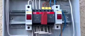
According to current technical standards (PUE, in particular), during the operation of any electrical equipment, increased attention is paid to protecting working personnel and private consumers from electric shock. Research into this problem typically involves technical issues such as:
- what is called protective grounding in general?;
- the ability to connect to circuit elements and select the type of grounding device (GD);
- What is preferable: protective grounding or so-called “grounding”?
Another important point is the user’s desire to become familiar with how the operating parameters of the ground electrode can be calculated and how this design works. Each of these issues regarding protective grounding devices requires separate and careful consideration.
Classification of grounding systems (natural and artificial structures)
Both natural and artificial systems and devices are widely used as grounding devices with characteristics that meet the requirements of the PUE. Natural storage facilities are metal structures and pipelines already buried in the ground or parts thereof that are in direct contact with the ground.
Additional information: These also include unbroken cable sheaths, metal tongues and similar elements of grounded structures and communication systems.
Natural grounding conductors of buildings and structures
Since there are absolutely no special costs required for the arrangement of such earthing devices, they are recommended for use in the first place by current standards. And only if natural grounding structures cannot be found, it is necessary to arrange their artificial analogue. To find out what is the definition of artificial grounding, you will need to understand it in more detail.
Such a system is understood as a device manufactured specifically for the purpose of organizing local grounding at a transformer substation or on the consumer side. Driven vertical or laid horizontal steel blanks are traditionally used as structural elements. In the first case, steel rods with a diameter of at least 12 mm and a length of 3-5 meters are used, and in the second, angles with a standard size of 50x50x6 mm are used. For the same purpose, metal pipes with a diameter of at least 6 mm can be selected.
Installation of a ground electrode in the ground
Vertical electrodes (see photo on the left) are driven into the ground to a depth of 2.5 meters, for which a trench about 0.5-0.6 meters deep is first prepared in it. The head of the driven electrode should protrude above the ground surface of the dug trench to a height of about 0.1-0.2 meters. Vertical structural elements are connected to horizontal jumpers for welding.
Please note: The trench system with the electrode rods placed in them must be covered with previously selected soil, cleared of large stones and foreign debris.
The choice of parameters of electrode rods and the depth of their immersion depend on the nature of the soil in a given area and the characteristics of its climatic conditions.
According to GOST and the current provisions of the PUE, the resistance Rz of the ground loop during the period of operation should be:
- no more than 8 Ohms with a substation supply phase voltage of 220/127 Volts,
- about 4 Ohms with a linear supply voltage of 380 Volts;
- no more than 2 Ohms with a power supply of 660/380 Volts.
These parameters are valid for the case when chargers are used in networks with voltages up to 1000 Volts. If they are installed for existing electrical installations with operating voltages above 1000 Volts and with low ground fault currents, the resistance is calculated using special formulas (see PUE).
Grounding in a two-wire network when there is no grounding. Thinking out loud
Many, of course, will not like this article, both from a technical point of view and from a security point of view. I already see how someone went to the PUE or TCP (in Belarus it’s called the “Technical Code of Established Practice”) to tell me that this cannot be done. This is most likely true, but I want to write an article. And there is nowhere to spend the earned karma on this site (in the sense of using these points to benefit yourself or someone else). Everything that is written below should not be taken as a call to action. Think of it as a reasoning exercise for your brain.
We will talk about two well-known problems in residential buildings where there is no separate grounding conductor, even in the form of dividing PEN into PE and N in the building’s ASU:
- How to ground yourself where there is no “ground”?
- Protection when the main neutral wire burns out
Without protective conductor
The only option for protecting a person from electric shock when a phase contacts an ungrounded (and not zeroed) body of an electrical device is possible with an electromechanical RCD.
There is also a PES (Potential Equalization System), but if it is not properly grounded it can carry an even greater risk. Everything is simple here, when current flows through a conditional floor - the human body - the body of the electrical appliance
The RCD will be triggered by the difference in currents flowing into and out of zero and phase.
That is, it doesn’t matter which path this current leak will take: phase-to-floor
,
zero-to-floor
or
phase and burnt-out zero to floor
- the RCD will work in any of these options. The same direction of these currents is important.
But in addition to security, there are difficulties that are sometimes insurmountable:
1.
The electrical appliance “bites” due to its design features (capacitors in the power supply).
2.
The electrical appliance initially did not “bite”, but began to “bite”, while it still works as before.
Reversing the plug in the outlet does not help. There is no money, time, etc. for repairs, I just want to eliminate the “biting” or even “twitching” and use it until it completely breaks. 3.
The electrical appliance does not “bite”, however, due to the presence of “walking” voltage on the body, it does not want to work normally (for example, a long USB cable from a computer to a printer, humming in the speakers of audio amplifiers, poor radio reception, etc.).
To get rid of these problems, many sacrifice safety by connecting the housings of electrical appliances directly to “grounding” in the form of heating pipes, fittings, or, if conditions permit, by burying a metal pin in the ground. The danger of these methods of “grounding” has long been known. In certain sections of the route, pipes may be connected with plastic rather than metal and have high resistance to grounding. Leakage currents from electrical appliances contribute to rapid corrosion of pipes. If a phase contacts the body, the circuit breaker or RCD may not operate if the flowing currents are small. There will be a risk of electric shock not only to the person who made such grounding, but also to all those who, by chance, found themselves in the affected area (a plumber changing a pipe or neighbors on the floor below and above).
Shield nullification
Here it is necessary to make a digression.
Although in our electrical networks the zero is connected to the ground loop at the transformer substation, due to the uneven current load across the phases, as well as the large length of cable lines, for remote consumers of electricity, the voltage between zero and ground can be more than ten volts. There is a voltage drop in the neutral wire too!
Standing on a wet concrete floor and touching your hands to the body of a zeroed water heater or a metal faucet connected by metal hoses, you can definitely feel this tension. And if you connect the neutral wire to metal pipes or other structures buried in the ground, such a weak current of several amperes can flow through them.
That is, even theoretically, not every neutral wire can be grounded if it is tightly screwed into the ASU with PEN divided into PE and N. Such cases happen, for example, when a building does not have its own ground loop. Potential will arise between the real ground (the connection point at the TP of the ground loop and the outgoing neutral wire) and the separated “ground” in the ASU of the building.
If the zero does not “bite”, then you can fantasize about how you can protect yourself with it while it is intact. And in order to know that it is intact, it is necessary to attach to a certain point which, at least in theory, will have a constant zero electrical potential (reference voltage) relative to the ground. This point can be the place where the neutral wire is connected to the grounding bus on the transformer substation, and the ground itself can be like an ideal conductor on which there is conditionally no voltage drop in the section “ground of the transformer substation - ground of the connected building.” Here, for example, is a quote from one comment on YouTube on the same topic
... there is such a concept (statistical (artificial 0), if you use it relative to natural 0 you can solve this problem much easier and cheaper). The difference between artificial 0 and natural reaches during distortions and phase breaks from 0.5 to 10 V. Tested empirically.
An important condition for such a “reference grounding” is the ability to pass through a current of sufficient magnitude to trigger the protection, while the resulting voltage between the “reference grounding” and the “natural ground” should not exceed dangerous values, for example 30 volts.
Where to find such a reference grounding in an apartment is a big question. We remove heating, water supply and gas pipes for the reasons described above. The option of connecting to the EMS in the bathroom, but it is not known how this EMS is connected to each other and to other apartments, is dangerous. It turns out that the only option is reinforcement in the walls and ceiling, welded together and having a resistance to real ground of less than 1 kOhm. Although in a brick or wooden building this may not be the case.
But if there is, then you can test its “quality”. Take a voltmeter and measure the voltage between the zero in the socket and the fittings in the wall. If it is not zero, but for example 3 or more volts, by shorting the zero and the armature through a 100 mA fuse, this fuse should burn out (provided that the resistance between the armature and the real ground is small). Or if the voltage between zero and the fitting is close to zero, connect a crown battery in series to the circuit, adding 9 volts.
A blown fuse is an indicator of a passed “reference ground” test.
For a theoretical experiment, you will need a four-pole electromechanical RCD or an AC type differential circuit breaker with a leakage current of 30 mA, as the most common.
Based on the fact that the protection circuit works relative to the “reference ground”, I draw the first diagram.
The diagram is similar to the diagram for connecting an RCD in a two-wire network, with the only difference being that the “protective” neutral conductor taken from the panel body is also connected through the third contact of the RCD, but from below. Situations:
A. The zero in the shield is intact. If leakage currents occur from the body of an electrical device to phase or zero, the RCD will notice the difference in the inflowing and outflowing currents, and the protection will operate.
B. Zero does not reach the shield body (break). The voltage on the case is relative to the “reference ground”. If the current flows along the chain “protective zero - housing - body - floor”, the RCD will also respond to this leakage.
And if it is necessary that the RCD does not trigger leakage currents from zero to the housing or from phase to housing? We set the protective zero on the upper contacts of the RCD. Now the currents are added and subtracted differently.
A. The zero in the shield is intact. If leakage currents occur from the body of the electrical device to phase or zero, the RCD will not notice the difference in the inflowing and outflowing currents, the RCD will not work.
B. Zero does not reach the shield body (break). The voltage on the case is relative to the “reference ground”. If the current flows along the chain “protective zero - housing - body - floor”, the RCD will respond to this leakage.
Zero break protection
The fourth contact of the RCD can be used as a zero break detector.
Again using our “reference ground”. As soon as a voltage of more than 30 volts relative to the “reference ground” appears in the shield on the protective neutral wire, a leakage current will appear and the protection will operate. Comment from the Internet
By the way, back in 2000. in a boutique on Podol in Kyiv (pre-revolutionary house, air input) I managed to get the RCD to react to a zero break. I placed a 1kOhm resistor between zero and clean ground (I made the circuit myself), with a normal voltage at zero 5V, the leakage from zero is 5mA, if the zero on it is broken at least 50V, leakage is 50mA, the RCD is turned off.
The downside of the resistor is a current of several milliamps at low voltages between ground and zero, that is, it can always hang 10-15mA, which is not good for everything else that is connected to the RCD that can operate, for example, at 17-20mA.
A varistor does not have a very good current-voltage characteristic, the resistance does not drop sharply when it breaks through, in addition, even if you limit the current with a resistor, it still has a limited number of operations.
Gas dischargers from 75 volts are too much. The resistance depends on the applied voltage.
It is much easier to assemble a circuit using diodes, a zener diode and a transistor. It is possible with two powerful zener diodes, but they are more difficult to find on sale.
Operating condition of the circuit:
- The minimum stabilization voltage of the zener diode Ust.min must be greater than the amplitude value of the voltage between the “reference ground” and the protective zero.
- The gain of transistor h21e should be no more than 20 - 40. So that units of microamps on the base do not turn into tens of milliamps on the collector. The transistor is an ordinary bipolar one.
- The current-limiting resistor of the circuit is selected from the condition that at 30V a current of 30mA should flow between the “reference ground” and the protective zero.
When the voltage between the “reference ground” and the protective zero is less than Ust.min, the current through the circuit is a few microamps. When the voltage increases to 30 or more volts, the current through the circuit will sharply increase to the 30 or more milliamps we need.
Everything together will look like this
or so
If there is no soldering of circuits, then you can install simple overvoltage protection between the working zero and the phase. When the zero burns out in the panel and more than 250 volts appear instead of 220, current will flow through the fourth contact of the RCD, and the protection will also work.
You can probably come up with many variations of schemes on this theme.
Considering that there are electronic voltage relays on sale or similar mechanical releases for RCDs and automatic machines from manufacturers of electrical products, such “Kulibinism” can be reduced to nothing or to a minimum. The main thing is to know that such protection devices exist and to have a general idea of where and how they are used.
PS
Important note from a discussion on one forum
what will happen if you use a 4-pole RCD, which connects a battery through its contacts to a zero in the shield, when someone wants to use it as a zero on the battery, not yours, but the neighbor’s? This means that then a much larger current will flow through the contacts of your RCD than originally expected
The important point here is that the “protective zero” on the housing can be electrically connected to water pipes, for example, when connecting a washing machine or water heater with hoses to pipes (not necessarily metal).
According to the protective zero, an equalizing current will flow through the body of the electrical device through the hoses to the battery, the RCD will trip, but currents even in units of milliamps are not good. Plus the situations described at the beginning of the article. For a better understanding of how differential current protection devices work and their unusual applications, I highly recommend watching the video series “Residual current devices against breakage, heating and arc” by ID - Vladimir Melnikov (on Vladimir Melnikov hub
).
Protective grounding and grounding
To understand what protective grounding , you will need to understand the features of the organization and arrangement. At the same time, it is important to learn to distinguish it from its working analogue, which is necessary for the normal functioning of the supply circuits. Protective grounding, in contrast to worker grounding, provides safe conditions for handling equipment, the open parts of which are energized in the event of an accident. However, there are often situations when it is not possible to equip a protective circuit at a specific facility. This may be due to the lack of conditions for its placement or other organizational reasons.
Important! To protect a person from electric shock in conditions where it is impossible to organize conventional grounding, protective grounding is used.
To understand in detail what this protective grounding is, you will need to familiarize yourself with the principle of its operation. The essence of this system is to connect exposed conductive parts that may be energized with a tightly grounded neutral of the supply line (transformer).
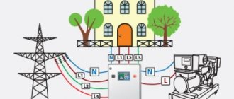
Protective grounding and grounding solve the same problem of ensuring human safety
Thus, protective grounding and grounding for electrical installations, as systems, solve the same problem of ensuring human safety, but each in its own way (see photo above). In the first case, to organize a chain of emergency current flow, a local grounding device is used, which reduces the high potential on the equipment body to a safe level. When arranging a grounding system, the neutral of the supply network is used, which makes it possible to turn an emergency situation into a regular single-phase short circuit. The scope of application of protective grounding is all cases where it is impossible to use a conventional grounding system.
What is more reliable: grounding or grounding?
Both protection systems are installed for the purpose of human life safety. The choice of one option or another depends on the location, the proposed circumstances, and operating conditions.
In all respects, grounding more reliably protects against accidental electric shock, thereby creating safety for a person’s life and work.
Grounding is used in old Soviet-built houses, where it is no longer possible to install a protective grounding loop. According to modern PUE standards, a protective grounding system is installed in new projects.
Purpose and principle of operation of protective grounding
It has already been noted that the electrical grounding system is designed to protect personnel servicing electrical installations and ordinary users from high voltage. Dangerous potential most often reaches metal parts of equipment or household appliances completely accidentally (due to damage to insulation, for example). The purpose and principle of operation of the charger is easier to understand if we remember that reliable contact with the ground leads to the spread of dangerous current and a decrease in the potential level.
Thus, the purpose of the protective device is to create conditions that reduce the risk of injury to living organisms by a dangerous current by reducing the voltage at the point of closure.
The principle of operation of the grounding system is to reduce the high potential that accidentally appears on the equipment body to a value that is safe for the human body. In the absence of functional grounding, unintentional contact with it is tantamount to direct contact with the phase conductor. Taking into account the fact that the operator most often stands on a reinforced concrete floor, and his shoes are not always dry, a significant current can flow through his body.
The presence of protective grounding creates conditions for the main part of the current from the system to flow into the ground
The presence of functional grounding creates the conditions for the main part of the current from the system to flow into the ground. Its share in the human body will be negligible and will not cause him any harm (see photo on the left). This guarantees the required level of electrical safety when working with a grounded device.
Additional information: Grounding systems, along with the technical grounding already known to us, are not the only options for ensuring safety during the operation of electrical installations.
Along with them, the PUE recommends for use special emergency power line shutdown devices (RCDs), which are triggered when leaks to the ground occur.
When and where is grounding applied?
As already mentioned, protective grounding is intended to eliminate the possibility of electric shock to people in the event of voltage being applied to conductive parts of the equipment, that is, in the event of a short circuit to the housing. Protective grounding is used to equip metal non-current-carrying elements of electrical installations, which, due to a possible breakdown of wire insulation, may become energized and cause harm to the health and life of people and animals if they come into direct contact with faulty equipment.
Electrical networks and equipment with voltages up to 1000 V are subject to grounding, namely:
- alternating current;
- three-phase with isolated neutral;
- two-phase, isolated from ground;
- direct current;
- current sources with an isolated winding point.
Grounding is also necessary for electrical networks and electrical installations of direct and alternating current with voltages over 1000 V with any neutral or midpoint of the current source winding.
How to calculate a system of grounding elements
Getting acquainted with the procedure for calculating grounding should begin with finding out what value to take as the defining indicator and for what purpose the procedure itself is used. This parameter is the resistance of the protective circuit, which depends on such technical indicators as:
- Dimensions and shape of the grounding system.
- The depth of its immersion into the ground.
- Condition of the soil in the area.
Important: A large “contribution” to the formation of the conductivity of the current flow chain is made by the contact resistance of the contacts in the design of the charger itself.
It is known that an artificial grounding loop consists of a set of vertical and horizontal metal elements and a copper busbar connecting them. In order to ensure minimal resistance to current flow into the ground, it is necessary:
- use grounding systems with a large area of contact with the ground (if necessary, increase the number of vertical pins and their pitch);
- constantly monitor the condition of the soil at the location of the device and be able to determine the soil resistivity;
- control the reliability of welded joints.
To assess the real performance indicators of the charger, it is necessary to familiarize yourself with the existing methods for measuring the conductivity of the grounding system.
What is the difference between grounding and grounding?
It’s worth saying right away that despite the fact that grounding and grounding are protective measures, they differ in their principle of operation and purpose. Grounding is a more effective and reliable method of protection than grounding, since it allows you to quickly equalize the difference between potentials to the required value. Also, grounding has a simpler design and is easier to install, and to install it you just need to follow the instructions. In addition, this protective circuit does not depend on the phase pattern of the connected equipment. Grounding options are varied, and this allows you to choose a specific type for each specific case
Difference between grounding and neutralizing
Protective grounding is a protective measure that, in the event of a network malfunction, simply ensures an instantaneous interruption of the supply of voltage from the electrical network by triggering an RCD. Creating grounding and connecting equipment requires experience and certain knowledge in electrical engineering. All installation work, especially determining the zero point, must be performed correctly, otherwise, in an emergency, electric shock may occur.
Having figured out what grounding and grounding are, many people prefer to use both methods. However, grounding is mandatory when installing household and industrial networks, as well as operating equipment.
To better understand the difference between grounding and zeroing, we suggest watching this video:
Typical calculation methods
To calculate protective grounding, you will need to determine in advance the following initial indicators:
- Dimensions and total number of steel pins driven into the ground.
- The distance left between them (installation pitch).
- Depth of rods.
- The resistivity of the soil itself at the site where the storage facility is installed.
In addition to them, it is important to take into account the geometric shape and material of the workpieces from which the system of grounding conductors is welded (either it is a standard steel angle, or a copper strip, etc.).
According to the current regulatory documentation (PUE, in particular), the minimum dimensions of the selected workpieces must be no less than:
- steel strip with a cross-section of at least 100 mm2;
- steel corner with sides 4x4 mm;
- round steel bar with a cross section of 16 mm2;
- metal pipe with a diameter of 32 mm and a wall thickness of at least 3.5 mm.
The minimum dimensions of the pins or reinforcing bars used to manufacture the charger system are selected from the following considerations. The length of the workpieces cannot be less than 1.5-2 meters. The distance between them is taken as a multiple of the length of each rod. Depending on which site is chosen for arranging the memory, they are installed either in a row one after the other, or in the form of a square or a regular triangle. According to the calculation method used, its main task is to determine the number of rods and the parameters of the connecting strip (its length and thickness).
To calculate all parameters of protective grounding, you can use the online calculator on our website.
Example of calculation of memory elements
As an example, let us consider the calculation of the resistance to emergency current drainage for a vertical rod taken in a single copy (drawing on the right).
Drawing of a vertical ground electrode
To carry it out you will need to know the following initial data:
ρ is the resistivity of the soil at this location (in Ohms per meter);
L – length of the rod in meters;
d – its main standard size (diameter) in meters;
T – distance to the middle of the rod from the surface in meters.
If we take into account the value limiting the flow of current for horizontal charger elements, then the resistance for their vertical analogues is calculated using the following formula:
Formula for calculating current spreading resistance for vertical grounding conductors
In a situation where the grounding device is installed in heterogeneous soil (experts call it two-layer), the resistivity is calculated as follows:
Formula for calculating resistivity for heterogeneous soil
where – Ψ represents the seasonal coefficient;
ρ1 and ρ2 – resistivity of various layers of local soil (upper level and lower layer, respectively), measured in Ohms per meter;
H – thickness of the layer located in the upper part of the soil in meters;
t – total depth of vertical elements (depth of the entire trench), equal to approximately 0.7 meters.
The required number of rods (excluding horizontal components) is determined as follows:
where Rн represents the spreading resistance normalized according to PTEEP.
If we take into account the horizontal components of the charger, the formula for the number of vertical pins will take the following form:
where η in is the system utilization coefficient, indicating how strongly the spreading currents from individual elements influence each other (at their different locations).
Additional information: When a system of rods is placed in parallel, the mutual influence of the spreading currents of individual pins is much stronger.
That is why, if they are located too close, the total resistance of the protective circuit increases significantly. The number of grounding elements obtained after using the above formulas is usually rounded up to a larger value. It is possible to automate the calculation of grounding based on them if you use the “Electrician v.6.6” program specially developed for this purpose. You can download this software for free on the corresponding website on the Internet.
Basic methods of grounding
When constructing a grounding system, vertical metal rods are usually used as a grounding conductor. This is due to the fact that horizontal electrodes, due to their shallow depth, have increased electrical resistance. Steel pipes, rods, angles and other rolled metal products with a length exceeding 1 meter and having a relatively small cross-section are almost always used as vertical electrodes.
Grounding diagram in a private house
There are two main methods for installing vertical ground electrodes.
Related article:
Electricity can not only create comfortable living conditions, but also carries a certain danger. To reduce the likelihood of this danger occurring, do-it-yourself 220V grounding in a private house . How to make it - read the publication.
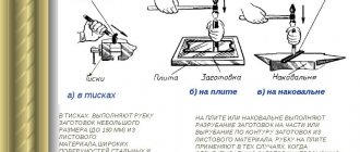
Several short electrodes
This option uses several steel angles or rods 2-3 meters long, which are connected together using a metal strip and welding. The connection is made at the surface of the earth. Installation of the ground electrode occurs by simply driving the electrode into the ground using a sledgehammer. This method is better known as “corner and sledgehammer”.
Using reinforcement as a grounding conductor
The minimum permitted cross-section of grounding electrodes is given in the PUE, but most often the corrected and supplemented values are from technical circular No. 11 of RusElectroMontazh. In particular:
- for corners and strips made of black steel with a cross-section of at least 150 mm2 and a wall thickness of 5 mm;
- for steel rod with a diameter of at least 18 mm;
- for steel pipes with a wall thickness of 3.5 mm and a diameter of at least 32 mm.
The advantages of this method are simplicity, low cost and availability of materials and installation.
Single electrode
In this case, an electrode in the form of a steel pipe (usually single) is used as a grounding electrode, which is placed in a deep hole drilled in the ground. Drilling the soil and installing the electrode requires the use of special equipment.
Single ground electrode mounted in a drilled hole
An increase in the contact area of the ground electrode with the ground is ensured by a greater depth of installation of the electrode. Moreover, this method is more effective in comparison with the previous option, with the same total length of the electrodes, due to reaching deep layers of soil, which usually have low electrical resistivity.
The advantages of this method include high efficiency, compactness and seasonal “independence”, i.e. Due to winter freezing of the soil, the resistivity of the ground electrode practically does not change.
Another way is to lay a grounding conductor in a trench. However, this option requires greater physical and material costs (more material, digging a trench, etc.).
This method requires a lot of physical effort.
Having figured out how grounding works and why it is needed, we now face the second question of our article, namely, what constitutes grounding, why it is needed and how it differs from grounding.
The difference between a working ground wire and a protective bus
The working and protective grounding conductors differ from one another, first of all, in their purpose. The first of them serves the purpose of providing the load with phase current, creating a circuit for its flow from the transformer to the consumer. The second one is used purposefully for arranging grounding systems (both on the station side and at the consumer).
Please note: In production or in private homes, for example, the grounding conductor is used to organize the so-called “local” or repeated grounding.
Thus, the main functional purpose of the operating bus is to create conditions for the uninterrupted operation of station and local electrical equipment by laying a line separate from the protective conductor. The grounding system functionally solves completely different problems - it creates conditions for the safe operation of this equipment. In addition, lightning rods installed in enterprises or private homes are connected to it. It is also used when it is necessary to create grounding systems and potential equalization in electrical installations.
Schematic diagram of dividing a PEN conductor into PE and N
In order not to confuse these two types of grounding conductors on electrical diagrams, letter and color designations have been specially introduced to indicate the method of their installation (combined or separate). In the first case, the common wire is designated as PEN , and when laid separately, they are functionally divided into PE and N , neutral or working (photo on the left). Depending on the design method of these two conductors, there are several types of grounding systems that are acceptable for use in Russian power supply networks.
The danger of zeroing in an apartment
Voltage surges are dangerous both for people and for household appliances in apartments. In apartment buildings, one of the apartments will receive low voltage, and the other will receive high voltage. If the neutral conductor breaks in an apartment socket, the next time the electrical installation (for example, a boiler) is turned on, the person will receive an electric shock.
Zeroing is especially dangerous in a two-wire system. For example, when carrying out electrical installation work, an electrician can replace the neutral conductor with a phase conductor. In electrical panels, these conductors are not always marked with a specific color. If replacement occurs, electrical equipment will become live.
According to the standards of the Rules for Installing Electrical Installations at the Household Level, grounding is not permitted for use for domestic purposes precisely because of its unsafety. Grounding is effective only for protecting large industrial facilities. However, despite the ban, some people decide to install zeroing in their own homes. This happens either due to the lack of other methods for solving the problem, or due to insufficient knowledge on this subject.
Zeroing in an apartment is technically feasible, but the effectiveness of such protection is unpredictable, as are the possible negative consequences. Next, we will consider a number of situations that arise when there is grounding in an apartment.
Grounding in sockets
In some cases, it is proposed to protect electrical appliances by jumping the terminal of the socket working zero to the protective contact. Such actions contradict clause 1.7.132 of the PUE, since they involve the use of the neutral wire of a two-wire electrical network as both a working and a protective zero at the same time.
At the entrance to the residential premises there is most often a device designed for switching phase and zero (a two-pole device or a so-called packetizer). Switching of a zero used as a protective conductor is not allowed. In other words, it is prohibited to use as protection a conductor whose electrical circuit includes a switching device.
The danger of protection using a jumper in a socket is that in the event of damage to the neutral (regardless of the area), the casings of electrical installations come under phase voltage. If the neutral conductor breaks, the power receiver stops functioning. In this case, the wire seems to be de-energized, which provokes rash actions with all the ensuing consequences.
Note! When the zero line breaks, any equipment in an apartment or private house becomes a source of danger.
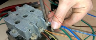
Phase and zero are reversed
When carrying out electrical installation work in a two-wire riser with your own hands, there is a considerable probability of confusion between zero and phase.
In houses with a two-wire system, the cable cores are devoid of distinctive features. When working with wires in a floor panel, an electrician may simply make a mistake by mixing up phase and neutral. As a result, the housings of electrical installations will come under phase voltage.
Zero burnout
Zero break (zero burnout) often happens in buildings with poor wiring. Most often, the wiring in such houses was designed based on 2 kilowatts per housing unit. Today, electrical wiring in old-type houses has not only worn out physically, but is also unable to satisfy the increased number of household appliances.
When the zero line breaks, an imbalance occurs at the transformer substation from which the apartment building is powered. Misalignment is possible in the general electrical panel of the building or in the floor panel of the house. The consequence of this will be a random decrease in voltage in some apartments and an increase in others.
Low voltage is detrimental to some types of electrical appliances, including air conditioners, refrigerators, hoods and other devices equipped with electric motors. High voltage is dangerous for all types of electrical installations.
Requirements, control, verification
When installing and operating grounding systems, increased attention is paid to monitoring their condition. Before carrying out these activities, it is first necessary to familiarize yourself with the content of the terms used to describe the procedures. “Inspection” means a visual inspection of grounding systems for compliance with the following requirements:
- reliability of contacts at the joints of charger elements;
- absence of signs of destruction on open parts of structures and supply copper busbars;
- the state of the protective paint, which is recommended to be renewed regularly, as well as the presence of markings on the supply conductors.
The word “monitoring” means periodic testing of grounding loops in order to determine compliance of their resistance to current flow with the established PUE standards. According to the requirements of this document, it should not exceed several Ohm units .
Additional information: To monitor the grounding condition, you will need measuring instruments connected to structural elements according to a special circuit.
According to the requirements of the PUE, existing chargers must be checked at least once every six months (visual inspection). The same procedure, accompanied by selective opening of the earth cover in suspicious places, is carried out at least once every 12 years. When organizing monitoring of the serviceability and reliability of the functioning of charger systems, they also proceed from the recommendations of the PUE, which determine which voltages do not need to be used when checking the resistance of the circuit, and which ones can be used.
In addition, standard methods of periodic control examinations require mandatory measurement of the resistance of the electrical circuit, called the “phase-zero loop”. This artificially created system is formed by shorting a single phase wire to the metal body of an electrical installation connected to the existing network.
In fact, such a loop is formed between the phase bus and the grounded zero, which was the reason for giving it this name. Knowledge of this parameter allows more precise control of grounding circuits in order to ensure the required protection efficiency (draining of emergency current into the ground). The safety of maintenance personnel and people working with household appliances depends on the resistance value of this circuit.
Briefly about the main thing
Grounding is the removal of voltage from the housing of electrical equipment to the ground through a grounding loop. There are professional, household and spontaneous versions. It can be artificial, specially created, or natural, when suitable metal structures are used as current transmitters.
Grounding differs from grounding in that the electric current during a breakdown on the housing is diverted not into the ground, but into the distribution panel. This artificially causes shortening, as a result of which the machine is triggered and the equipment is de-energized. The main differences between them boil down to the following features:
- Grounding drains the current into the ground, and grounding into the shield.
- Grounding reduces the voltage on the case, grounding completely de-energizes the circuit.
- Making a grounding circuit is accessible to any more or less literate person; protection through “zero” can only be arranged by a professional.
- Protection through grounding is more suitable for industrial facilities, grounding - for residential ones.
Grounding in the house is suitable as a temporary measure until a full-fledged grounding loop is created in the yard. It is necessary to equip protection across the “zero” with careful selection of suitable conductors and compliance with electrical installation rules.
How to determine the resistance of a phase-zero loop
The requirements contained in the PTEEP rules require constant monitoring of the condition of the chargers, ensuring the safe operation of household and industrial electrical equipment. According to these standards, in systems up to 1000 Volts with a tightly grounded neutral, they must be checked for a single phase fault. The testing methods used are, first of all, based on the technical base represented by samples of special-purpose measuring instruments.
Measuring equipment
To check the resistance of the “phase zero” circuit circuit, electronic devices are traditionally used, characterized by a small measurement error. The most famous examples of measuring equipment of this class include:
- Meters of the M 417 and MSC 300 brands, allowing to determine the conductivity of controlled circuits (based on the results obtained, short-circuit currents into the ground are calculated using special formulas).
- The EKO-200 device is intended exclusively for determining short-circuit currents. The EKZ-01 device is used in exactly the same way as the EKO-200.
- Measuring device brand IFN-200.
M417 can be used when organizing and carrying out measurements in three-phase circuits with a tightly grounded zero (in this case, removing the supply voltage is not required). During the tests, the voltage drop method is used when the controlled circuit is opened for a time of about 0.3 seconds. The inconveniences of working with this device include the requirement to calibrate it before starting each new measurement.
Phase-zero circuit resistance meter brand M 417
The MSC300 product is a more advanced technical device, equipped with complex electronic filling in the form of modern microprocessor chips. When working with this device, the method of reducing the potential is used by including a resistance of 10 ohms in the measured circuit. The operating voltage varies from 180 to 250 Volts, and the measurement time of the desired parameter is about 0.03 seconds. When taking measurements, it is connected to the monitored line at the most remote point, and to start working with it you will need to press the “Start” button. The measurement results can be viewed after they are displayed on the built-in digital display.
MZC-300 meter for parameters of power supply networks of buildings and structures
In a situation where the user does not have a single sample of special measuring equipment at his disposal, a standard voltmeter and ammeter can be used to practically determine the resistance of the phase-zero loop. The required result is found using the simplest formula, familiar to many from the school physics course.
What is zeroing
The term grounding refers to the intentional connection of open non-current-carrying conductive parts of the electrical network and equipment with a solidly grounded point in single- and three-phase DC and AC networks. Grounding is performed for electrical safety purposes and is the main protective measure against voltage.
Grounding for three- and single-phase electrical networks
Operating principle
A short circuit in the electrical network occurs when an energized phase wire comes into contact with the body of the device connected to zero. The current increases sharply, and protective devices are activated, cutting off power from the faulty equipment. According to the rules, the response time of the RCD to disconnect a faulty electrical network should not exceed 0.4 seconds. To do this, it is necessary that the phase and zero have an insignificant resistance value.
Related article:
Have you ever heard the abbreviation RCD? what it is by reading the review to the end. Briefly, I would like to add that this device is capable of protecting housing and all its inhabitants from emergency situations related to electricity.
Grounding circuit
To create a grounding in a single-phase network, as a rule, the third (unused) wire of a three-core cable is used. To create good protection, it is necessary to ensure a high-quality connection of all elements of the grounding system.
Device
The grounding system, for example, in an apartment building, begins with a grounded power transformer, from which the neutral with a three-phase line comes to the main distribution board (MSB) of the building. Next, wiring occurs to the floor electrical panels. A working zero is created from the neutral, which, together with the phase wire, forms the usual single-phase voltage.
Scheme of the grounding device from the substation to the apartment
The grounding itself to protect the electrical network and equipment is created in the panel using a conductor connected to a grounded neutral. You should know that it is forbidden to install switching devices (automatic machines, packets, switches, etc.) between zero and neutral.
Where is the zeroing scheme used?
According to the requirements of the PES, the following must be equipped with protective grounding:
- single- and three-phase AC networks with a grounded terminal and voltage up to 1,000 V;
- DC power networks with a central grounding point and voltage up to 1,000 V.
Grounding cannot protect against electric shock like grounding. This protective circuit simply cuts off the voltage supply in the event of a short circuit and turns off the local power grid.
conclusions
In the final part of the review, we note that the scope of application of protective grounding systems is all electrical equipment operating both on the consumer side and within the boundaries of the transformer substation. These devices are characterized by the fact that they provide conditions for the safe work of maintenance personnel (protect them from electric shock). After getting acquainted with the features of their arrangement and calculation, not a single user should have any doubts about why grounding is needed when operating electrical installations.
An alternative to zeroing
In the TN-S subsystem, grounding of the protective conductor PE is carried out only in one area - on the grounding circuit of the transformer substation or electric generator. At this point the PEN conductor is separated, and then the protection and working zero do not meet anywhere.
In such a power supply scheme, grounding and grounding organically interact, creating conditions for high electrical safety. However, in systems where the neutral is isolated (IT, TT), grounding is not used. Electrical equipment operating within the TT and IT system is grounded through its own circuits. Since the IT system involves supplying power only to specific consumers, it makes no sense to consider this method of organizing protection in residential buildings. The only alternative to incorrect and therefore dangerous zeroing of the PE bus is the TT system. Such a system is especially relevant, because the transition to technically advanced systems TN-S, TN-CS is technically and financially difficult for houses whose age exceeds 20 - 25 years.
The electrical network, built according to the TT standard, is designed to provide high-quality protection against energized non-current-carrying parts. All work on organizing grounding must be carried out in accordance with the standards specified in paragraph 1.7.39 of the Electrical Installation Rules.
Grounding concept
Before answering the question of how grounding differs from grounding, let’s consider each concept separately. Grounding is a special connection of electrical installations to the ground. The purpose of this connection is to reduce sudden voltage surges in the electrical network. It is used in the circuit where the neutral will be isolated. When suitable grounding equipment is installed, the excess current that enters the network will flow into the ground through the outlet contacts. The resistance of this part must be relatively low so that the current is completely absorbed.
Also, the function of protective grounding of electrical installations allows you to increase the volume of emergency fault current, despite the fact that this contradicts its purpose. A grounding electrode with high resistance may not be able to withstand a weak fault current, only with special protective devices. In this case, when there is an emergency, the installation will be energized, which can pose a great danger to human health in this room. The purpose of protective electrical installations is also designed to remove stray current in the electrical network.
The ground electrode is a special conductor that may consist of one or more elements. They are usually connected to each other by electrically conductive material and are embedded in the ground, which absorbs the passing charge. Steel and copper can be used as grounding conductors. According to the PUE standards, this protective measure must be taken in modern residential buildings, as well as work premises, factories, public institutions and other buildings for various purposes.
Most modern homes have grounding circuits installed. However, they may not be present in older buildings. In such a situation, experts recommend replacing the wiring with a three-core cable with a grounding wire, connecting a protective electrical installation. There are situations when it is not possible to install a complete grounding loop. In modern electrical engineering, special portable equipment can be used - a portable grounding pin (bus). Their action corresponds to the standard grounding device of residential buildings or taps. Such a device has good practical value, is easy to install, carry, repair, and also has a wide range of functionality.
The grounding function can be performed by several independent groups of protective equipment. Lightning protection. They serve to quickly remove high pulsed charge from lightning. Often their use is necessary in arresters and modern lightning rods. Workers. This group allows you to maintain the required operation of all electrical installations under different conditions (normal and emergency).
Protective. This group of equipment is needed to prevent direct contact of people and animals with an electrical charge that occurs as a result of mechanical damage to a phase in the wire. They prevent many accidents that could occur if problems with the power line were not noticed in a timely manner.
Grounding electrodes are conventionally divided into artificial and natural. Artificial electrical installations are special structures that I make specifically in order to divert excess network current into the ground, providing protection for my home. They can be produced in a factory or made independently using steel elements. Natural grounding conductors are the soil, the foundation under a building, or a tree near the house.