Nowadays, rewinding the stator of an angle grinder can be done independently. To do this, you need to stock up only with the necessary knowledge. If the master has the necessary tools, skills in carrying out repair work and a certain amount of knowledge in the field of electrical engineering, the question of how to fix the malfunction of this tool with your own hands can be solved quite easily.
Stator winding diagram.
Causes of breakdowns
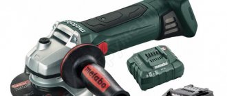
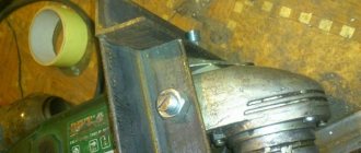
408-105 Stator for Hitachi G18SE3 and HAMMER angle grinders. Photo 220Volt
The most common cause of failure of the stator of an angle grinder is a violation of operating conditions . Asynchronous motors have the ability to maintain speed regardless of the magnitude of the current load. This is both an advantage and a disadvantage.
The ability to perform work under heavy loads is accompanied by overheating of the tool , which during long-term operation contributes to the occurrence of malfunctions in the rotor and stator windings . Under the influence of high temperatures, the protective layer of the insulating coating burns out, which leads to failure of electrical components.
Wound rotor design
The phase rotor of the IM is structurally similar to its stator. The rotor base is made of electrostatic steel plates, which are mounted on the shaft. The design has longitudinal grooves into which the turns of the phase winding coils are placed. The number of rotor phases strictly corresponds to the number of stator phases. To connect the rotor winding to the circuit, 3 slip rings are installed on the latter’s shaft, to which the ends of the winding are connected, which are in contact with the conductive brushes. In turn, the brushes have outlets into the housing box, which will allow you to connect external additional resistance.
Depending on the network voltage, the winding phases are connected in a “triangle” or “star”. The axes of the coils of a two-pole electric motor are shifted 120 degrees relative to each other.
Slip rings are made of brass or steel. They are mounted on the shaft with mandatory insulation between each other. The brushes are located on a brush holder, made of metalgraphite, and pressed against the rings by means of springs.
How to call
For high-quality diagnostics of the angle grinder stator, you should completely disassemble the power tool in order to remove all other structural elements, including the rotor, to ensure free access to all its parts. At the initial stage, it is necessary to perform a visual inspection. For a more complete picture, you should definitely check for defects using electrical instruments. What devices and how to ring the stator of an angle grinder are described in detail at the link “How to ring the stator of an angle grinder.”
Rotor
The rotor in an asynchronous electric motor is a shaft on which a core made of sheets of electrical steel is fixed. Whether a three-phase or a single-phase motor, the rotor has almost the same design. As a winding in conventional asynchronous motors with an operating frequency of 50 Hz, pieces of copper or aluminum wire of large thickness or rods connected to each other by end closing rings are used.
In order for the winding to be securely held in the core, there are special grooves into which it is pressed. The end rings can be equipped with ventilation blades designed to improve the cooling intensity of the internal space. The shaft is mounted on bearings pressed into flanges or plates attached to the frame, depending on the device.
There is a gap between the shaft and the stator , the size of which depends on the starting parameters of the motor. If it is necessary to increase power and torque, then it should be as small as possible. Simultaneously with the increase in power, additional losses in the upper layers of the stator and rotor also increase.
Winding diagram, how to choose wire thickness
The stators of angle grinders have a very similar design and differ in the size of the parts in which the magnetic flux is formed, the number of turns in the windings and the diameter of the wire. The standard connection diagram for grinders is shown in the following figure.
Here L1 and L2 denote the stator coils.
The burnt winding is removed, and it is necessary to collect information about the old coils : determine the number of turns, wire diameter, beginning, end of the winding and the required direction during rewinding work. The number of turns is determined by direct counting of wires after cutting the failed coils.
The diameter of the wire should match the windings being replaced as closely as possible. Therefore, the most suitable measuring tool is a micrometer with a measurement accuracy of up to 0.01 mm. The measurement is carried out on the surface of the wire of the burnt coil, stripped of the insulating coating.
Differences between electric motors in industrial production
Large enterprises with large production areas require equipment operating at high capacities. The technical characteristics of electric motors allow such machines to operate at powers ranging from 1 to 2.5 kW.
Why do you need air conditioning?- Batteries with a protective board: features, differences
What is the operating principle of a boiler room?
In woodworking production, machines of three-phase type and asynchronous operating principle are used. At the same time, they operate without problems at a household voltage of 220 Volts.
Distinctive features of such engines are:
- high power performance with small dimensions;
- increased rotation speed;
- protection from moisture;
- durability and performance.
How to rewind at home, stages of work
Repair begins with removing the failed old winding . Using pliers (pliers, round nose pliers) the stator slots are freed from the old winding.
Next, the stator coils are rewinded . It can be performed on a specially manufactured template or directly into the grooves of the stator core. This depends on the depth and width of the space for laying the wire.
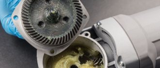
The wound coil is installed in the stator with the obligatory positioning of the beginning and end of the winding wire, as described above in the text. The winding is fixed in the stator with all gaps maintained (fastening options will be discussed further in the videos below). The stator is heated in the oven to approximately 80°C - 110°C. Using a brush, apply varnish or pre-prepared epoxy resin with a hardener. When applying, it is important to achieve the deepest possible penetration of the impregnation.
Practical advice on rewinding stator windings is given in the following videos.
Rewinding reels using a template
The author of the following video restores the stator of an angle grinder of the Temp model using items that can be easily found in any household. So the base (template) for winding the wire was a can of air freshener. Important : the diameter of the canister must correspond to the diameter of the wire sample formed according to the dimensions of the stator grooves.
Rewinding windings directly on the core
The following video describes in detail the technology for repairing the stator of an angle grinder . The author shows all stages of work and argues for his choice of rewinding the winding directly on the hardware. This model has wide grooves , and it will be difficult to fit the finished coil tightly into them. The author uses a plate as a guiding device, which he bends to the height of the corresponding extreme point of laying the winding in the grooves. The surface of the plate is covered with electrical tape to protect the wire insulation from damage and is fixed to the core with the same electrical tape. The process of such rewinding is quite labor-intensive. With a large number of turns, you should record your actions , for example, with appropriate notes on paper. This will help avoid mistakes.
After winding is completed and the guide plate is removed, the coil may weaken its laying due to residual stresses, and individual turns may fall out of the total mass. In this case, tying with a thread made of natural material (synthetics cannot be used) will help maintain the winding density. The use of various wedge objects allows you to fit the coil tightly into the grooves. However, the author does not encourage their use, as this negatively affects the quality of impregnation.
It's not always possible to choose the right template
In the following video, the author warns those who do do-it-yourself rewinding about the difficulties in choosing a template . It is not always possible to choose the right one right away. Guaranteed high-quality rewinding is provided by a much more labor-intensive but reliable method directly on the hardware.
Repair technology with a detailed description of varnish impregnation after rewinding
The author of the following video describes all stages of work: from disassembling, determining the number of turns, selecting wire material to rewinding using a template and impregnating the assembled stator with varnish. The impregnation process , which is carried out with ordinary varnish for interior work, is shown in detail The best option, of course, is to use shellac , which has good insulating properties. However, since some times this varnish has become a scarce material.
Source
Application area
The induction motor has become widely used as traction, secondary and other types of power components. Considering the features of its design, the absence of sliding contacts, the operation of such a motor is much simpler. Also, the connection diagram does not require complex control devices, if we talk about a simple operating mode with a constant frequency. Plus, the service life before service is much longer, since the internal space and windings are not contaminated with graphite.
An asynchronous electric motor is used in many areas:
- Ventilation systems – due to their durability and ease of operation, motors with squirrel-cage rotors are often used as fans. They withstand long-term operation at maximum speed, providing users or process equipment with intense air flow.
- Conveyors - due to their high torque and ability to maintain it under load, asynchronous motors have become an ideal option for implementing control of moving production lines.
- Servo systems and drive devices - asynchronous motors are especially often used in drive systems on technological equipment. But to organize control of this type of motor, a special connection diagram and a frequency control unit will be required, and the rotor of an asynchronous motor is equipped with neodymium magnets. Such motors are designed to operate at frequencies up to 400 Hz.
- Household sphere. From such a motor you can make various working units for household use or for a small workshop: a fan, controlled dampers, a circular saw, a jointer, and other equipment.
Simplified grinder repair
The article describes technological tips that simplify the complex and labor-intensive processes of winding armatures and stators of electrified tools. The article briefly describes the designs of electric motors for hand tools, provides diagrams of the windings and their connections, drawings of the device and a detailed description of the technological processes for their repair and installation.
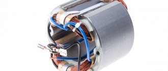
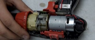
Most hand-held electrified tools (mainly electric drills, hammer drills, grinders, circular saws, screwdrivers, chain saws, etc.) contain mains commutator electric motors, which mainly consist of a stator with two electromagnetic poles, an armature
( Fig. 1) and a brush mechanism with two graphite brushes. The main causes of electric motor failures are violations of production technology, mechanical overloads and exceeding the duration of continuous operation. As a result, the winding wire overheats, which expands, which destroys its insulation and leads to short circuit of the turns. It is also possible that the ends of the windings may break from the commutator lamellas if they do not have a bandage. The methods for repairing armature and stator windings described in the literature recommend a complex technology of rewinding with wire of the same diameter, as a result of which it is necessary to wind 1000-2000 turns of thin wire using special devices [1]. And this requires appropriate experience, knowledge and hard work.
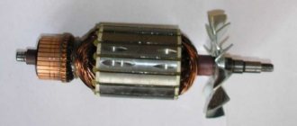
Most often, motor armatures fail, which have a more complex design and more dense laying of the winding wire in the armature grooves. The presence of short-circuited turns or broken ends of the windings in the armature, with working brushes and commutator, manifests itself in the form of circular sparking of the brushes, rapid heating of the tool and loss of engine power. Breaks in the ends of the windings are eliminated by soldering the ends to the commutator lamellas, applying a bandage of threads and uniformly impregnating it with epoxy glue. The complexity of rewinding an armature is an order of magnitude higher compared to rewinding a stator; moreover, it requires its static and dynamic balancing, so most often the authors of publications suggest replacing them with new, factory-made ones. This is the easiest, but expensive.
Having encountered a similar problem with my “grinder” and having determined that its mechanical part was in good condition, I felt sorry to throw it away, and it was decided to rewind its armature, which had windings with darkened insulation. I was further convinced of the presence of short-circuited turns by measuring the inductance of the windings between adjacent commutator lamellas with a Mastech type MY6243 multimeter. It is impossible to determine this with a tester, since the fraction of the resistance of one short-circuited turn is negligible compared to the resistance of the entire winding, but the short-circuited turn significantly affects the inductance of the winding. The authors of publications on the Internet on the repair of electric motors recommend burning out the armature windings, since they are impregnated with glue or varnish - it is impossible to simply remove or unwind them. The burning process requires the removal of ball bearings and can lead to shaft deformation, which is recommended to be eliminated by high-precision turning of the armature on a lathe after rewinding it. Naturally, I rejected this and used another technology.
Wrapping a strip of thick soft cardboard around the anchor, I pressed it in a vice so that it held tightly and did not deform. Using a hacksaw for metal with fine teeth, close to both ends of the grooves of the working part of the armature, I cut the windings, turning and rearranging the armature several times. The ends of the cut winding sections should not protrude from the armature grooves. After this, the anchor is lightly clamped in a vice with the ends of the working part. A steel rod with a flat end and a diameter slightly smaller than the width of the armature groove is selected. Using this rod and a hammer, parts of the cut winding sections are pressed out. At the same time, the wedges that secure the windings in the upper parts of the grooves are also pressed out. The wedges must be preserved. After this, the anchor must be prepared for winding the wire.
To facilitate the process of winding the armature, it was decided to use the PEV-2-0.5 wire, thicker than that used in the armature, and as a result, with the corresponding rewinding of the stator windings, the motor will become low-voltage. What the operating voltage of the tool will be is not so important and will be determined during testing by powering it from the LATR. The main thing is that the tool works. Considering that the engine will be low-voltage, it was decided to abandon the insulating gaskets and insulate the grooves and ends of the armature by applying a thin layer of epoxy glue. All sharp corners at the joints of the grooves and the end part of the armature are rounded off with a round needle file before applying glue. It is advisable to polish the collector lamellas with zero-grade sandpaper and clean the gaps between them. The places where the ends of the windings are connected to the lamellas must be cleaned and tinned. After applying and polymerizing the glue, the armature is ready for winding.
This anchor has 12 grooves and 24 collector lamellas. The brushes are placed perpendicular to the axis of the stator poles. Considering that the armature uses a loop winding scheme, four sections will be placed in each slot. The winding diagram for this motor option is shown in Fig. 2 [2]. The armature poles are shown at the top, and the commutator lamellas at the bottom. The diagram shows that four sections begin to appear in the groove between poles 5 and 6, and end at the end of the winding between poles 4 and 5. If the motor brushes are located along the axis of the stator poles, then the ends of the windings should be offset by 90 °, that is the ends soldered to lamella 1 must be soldered to lamella 7, etc. This important point is mentioned in the literature very vaguely or not mentioned at all [1].
Based on the cross-sectional area of the groove, the cross-section of the new winding wire, and taking into account the fill factor, it was determined that 40 turns fit into one groove. The number of turns of one section will be equal to 10. The small number of turns of the section and the increased wire diameter of up to 0.5 mm allows you to wind the armature manually without special devices and large labor costs. To wind the wire, the armature is carefully clamped through soft gaskets into a table vise with the fan impeller with the commutator facing toward itself. The coil of wire is located at the bottom on a horizontal rod. The end of the wire is stripped and soldered to lamella 1.
At the beginning of winding, the wire near the collector is slightly pressed in the direction of the shaft with your left hand, and the first turn is wound with your right hand. The deflections of the ends of the wire near the collector are necessary for winding the bandage at the end of winding the armature and must be the same. During the winding process, it is necessary to constantly monitor the absence of short circuits of the wound wire to the body, so as not to rewind everything again later. To do this, several turns of bare wires are wound around the commutator and the armature shaft, to the ends of which an ohmmeter is connected. Subsequent turns continue to be wound with the right hand, and with the left hand the wire is evenly laid on the ends of the armature and held to align and lay the wire in the grooves. The end of the section is formed into a bandage, stripped, folded in half, compressed with pliers to eliminate the loop, soldered to the next lamella and is the beginning of the next section.
As winding proceeds, the armature is moved in a vice to the desired angle, and the wire in the grooves is sealed with a flat wooden stick. The end of the last section is soldered to lamella 1. After winding all sections, a bandage of thin threads is wound onto the wire near the collector. After this, it is necessary to update all solderings and make them as identical as possible. This and subsequent uniform impregnation of the windings and bandage are necessary to maintain static and dynamic balancing of the armature. The author's version of the repair succeeded. Before impregnation, you can heat the anchor and epoxy glue to approximately 40°C on a room radiator or oil radiator. To protect against glue, wrap a couple of turns of electrical tape around the collector. The glue is evenly applied with a narrow wooden spatula, first on the bandage and then on the end parts of the sections on the collector side. Hold the anchor vertically with the collector slightly upward. After this, apply glue to the grooves and insert the wedges. Next, secure the armature vertically in a vice with the collector down by the ball bearing through soft cardboard and apply glue to the end parts of the sections on the side of the fan impeller. Such fastening will make it possible to rotate the anchor and monitor the leaking glue in order to promptly remove excess and level its surface.
For this purpose, the spatula must be soaked in machine oil. The polymerization process of epoxy glue occurs slowly and lasts about 4 hours, so after the first 30 minutes you can monitor the process less frequently and periodically turn the anchor in a vertical position. After complete polymerization of the glue, the armature is ready to be installed in its place, but after rewinding the stator windings.
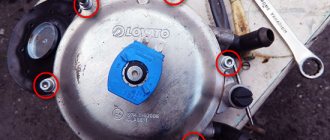
To rewind, the stator must be removed from the housing. In the author's version, the stator is tightly inserted into the place molded for it in the housing, all the way to the back. Its front part is fixed by a plastic cylinder, which with two protrusions rests on the stator between the windings, and with four protrusions on the removable gearbox housing. To remove the stator, you need to disconnect its four leads and pull it out of the housing.
If the stator cannot be removed in a simple way, then it is necessary to use a screw mechanism, for example, shown in Fig. 3,
1 - upper support plate;
4 - centering washer;
5 — lower support plate.
It may be necessary to place wooden slats on the sides of the stator between the top plate and the housing.
Based on the fact that the stator windings are connected in series with the armature brushes, and the upper and lower parts of the armature windings are connected to the brushes in parallel, the cross-section of the stator wire should be twice as large as the armature wire. Considering that the stator windings are less dense and cool better, this ratio can be reduced to 1.8-1.9. The ratio of the number of stator turns to the number of turns in the armature slot in a real motor is 3.4. In this option, both stator windings must have 40 × 3.4 = 136 turns. As a result, the stator windings were wound with PEV-2-0.62 wire, 70 turns each.
To wind the windings, it is necessary to make a mandrel. To do this, a rectangle with rounded ends is cut out of plywood with a thickness equal to the width of the stator slot. The width of the rectangle is equal to the width of the narrow part of the pole plus 5 mm, its length is 2 cm greater than the length of the stator. Two cheeks are cut out of thin plywood or textolite, the width and length of which are 2 cm greater than the previous part. At the corners, one cheek is attached symmetrically to the inner part with short screws (4 pcs.), in which a hole is drilled near the inner part to secure the wire of the beginning of the coil (Fig. 4).
The second cheek is secured with a nut during assembly. A through hole with a diameter of 8.2 mm is drilled in the center of the mandrel. A bolt or stud with M8 thread is inserted into this hole and the mandrel is clamped using nuts, as shown in Fig. 5, where the following are indicated:
4 - internal part;
The second coil is wound in the same way. The coil leads should be directed towards the commutator and have a margin in length in case of reversal of the polarity of the leads in relation to the commutator brushes if the motor rotates in the wrong direction. The motor stator is placed on the table with the pole down. The first coil is mounted on it. Strips of paper insulation are glued into the grooves of the poles with quick-drying glue. First, one side of the coil is inserted, then by stretching it across the width, the second side of the coil is inserted. After this, the stator is turned over and the second coil is mounted in the same way. It is very important that when installing the coils, when they are at the bottom, their origins are on the same side. And when assembled, the beginnings of the coils will be diametrically opposed. The protruding end parts of the coils are molded as shown in Fig. 6 and impregnated with epoxy glue along with the side parts.
After polymerization of the glue, the engine is assembled, the ends of the stator windings are soldered to the contacts of the brush holders according to the diagram in Fig. 7 , the insulation resistance is checked, which must be at least 1 MOhm.
Graphite brushes are replaced with copper-graphite ones, since with the same power and lower supply voltage the motor current will increase, at which the graphite brushes will overheat. In the author's version, used brushes from a car starter were processed on a sharpening machine to fit the size of graphite brushes. After this, the engine is connected to the LATR and started by gradually increasing the voltage. If the direction of rotation is reversed, then the stator leads connected to the brushes must be swapped. After this, the tool is finally assembled and tested for performance and heating under real metal cutting conditions for about 10 minutes. In this case, they measure with a voltmeter the voltage at which the tool operates in the same way as before, based on the experience of its previous operation. In the original version, the instrument operates normally on a voltage of 50 V. For ease of operation, a step-down transformer with secondary winding terminals of 40 V, 50 V and 60 V is manufactured in case of fluctuations in the network voltage. In addition, the transformer isolates the 220 V network from the tool, which increases the electrical safety of work. If you power the tool with direct current, its power will increase at a lower supply voltage, and heating will decrease due to the absence of Foucault currents in the stator.
In conclusion, it is useful to note that increasing the diameter of the winding wire increases the percentage of copper in the slot relative to its insulation, since several thin conductors with the same total cross-sectional area contain internal insulation, which takes up more space than the insulation of a single thick conductor. By observing the above recommendations and the ratio of the turns of the stator and armature windings, you can thus repair most of the power tools listed above, and also, during repairs, make a tool for a voltage of 12 V and power it from the vehicle’s on-board network in places where there is no industrial network 220 V / 50 Hz
Literature
Author: Anatoly Zhurenkov, Zaporozhye
Source: Radioamator magazine No. 9, 2015
Source
Rewinding an electric motor with your own hands: step-by-step instructions
In many household devices and home-made structures, low-power electric machines are used as a drive.
Despite the high reliability of electric motors, their failure for a number of reasons is not uncommon. Given the relatively high cost of these devices, it is more practical to repair them rather than replace them.
We suggest considering the possibility of rewinding electric motors at home.
Types of electric motors and features of their repair
As a rule, brushed DC motors and brushless asynchronous AC motors are used in everyday life. It is the repair of these drives that we will consider. Information about the operating principle and design features of asynchronous and commutator machines can be found on our website.
As for synchronous drives, they are practically not used in everyday life, so this topic is not touched upon in this publication.
Features of repairing an asynchronous machine
Engine problems of any type can be mechanical or electrical in nature.
In the first case, strong vibration and characteristic noise may indicate a malfunction; as a rule, this indicates problems with the bearing (usually in the end cover).
If the malfunction is not corrected in time, the shaft may jam, which will inevitably lead to failure of the stator windings. In this case, the thermal protection of the circuit breaker may not have time to operate. “Burnt” wires of the stator winding
Based on practice, in 90% of failures of asynchronous machines, problems arise with the stator winding (break, interturn short circuit, short circuit to the frame). In this case, the short-circuited armature, as a rule, remains in working condition. Therefore, even if the damage is mechanical, it is necessary to check the electrical part.
Winding check
In most cases, the problem can be detected by its appearance and characteristic odor (see Figure 1).
If the fault cannot be determined empirically, we proceed to diagnostics, which begins with a continuity test.
If one is found, the engine is disassembled (this process will be described separately) and the connections are thoroughly inspected. When no defect is detected, a break can be established in one of the coils, which requires rewinding.
If the continuity test does not show a break, you should proceed to measuring the winding resistance, taking into account the following nuances:
- the insulation resistance of the coils to the housing should tend to infinity;
- for a three-phase drive, the windings must show the same resistance;
- For single-phase machines, the resistance of the starting coils exceeds the readings of the working windings.
In addition, it should be taken into account that the resistance of the stator coils is quite low, so to measure it it makes no sense to use devices with a low accuracy class, such as most multimeters. You can correct the situation by assembling a simple circuit using a potentiometer with the addition of an additional power source, for example a car battery.
Circuit for measuring winding resistance
The measurement procedure is as follows:
- The drive coil is connected to the circuit presented above.
- The potentiometer sets the current to 1 A.
- The coil resistance is calculated using the following formula: , where RK and UPIT were described in Figure 2. R is the resistance of the potentiometer, and is the voltage drop across the measured coil (shown by a voltmeter in the diagram).
It is also worth talking about a technique that allows you to determine the location of the interturn short circuit. This is done as follows:
The stator, freed from the rotor, is connected through a transformer to a reduced power supply, having previously placed a steel ball on it (for example, from a bearing). If the coils are working, the ball will move cyclically along the inner surface without stopping. If there is an interturn short circuit, it will “stick” to this place.
Steel ball testing
Features of repair of commutator drives
This type of electric machine is more likely to experience mechanical failures. For example, brushes worn out or commutator contacts clogged. In such situations, repairs come down to cleaning the contact mechanism or replacing graphite brushes.
Testing the electrical part comes down to checking the resistance of the armature winding. In this case, the probes of the device are applied to two adjacent contacts (lamellas) of the collector, after taking readings, measurements are taken further in a circle.
Checking the armature winding of a commutator motor
The displayed resistance should be approximately the same (taking into account the instrument error). If a serious deviation is observed, then this indicates that there is an interturn short circuit or open circuit, therefore, rewinding is necessary.
Motor winding data
This is a reference data, so the most reliable way to obtain this information is to consult the appropriate sources. This data can also be provided in the product passport.
You can find advice online that recommends manually counting the turns and measuring the diameter of the wire when rewinding. It's a waste of time. It is much easier and more reliable to find all the necessary information using the engine markings, which will indicate the following parameters:
- rated operating characteristics (voltage, power, current consumption, speed, etc.);
- number of wires for one slot;
- Ø wire (as a rule, insulation is not taken into account in this indicator);
- information on the outer and inner diameter of the stator;
- number of grooves;
- with what step the winding is performed;
- rotor dimensions, etc.
Below is a fragment of a table with winding data for electric machines of type 5A.
Example of a table with winding data
Step-by-step instructions for rewinding an electric motor with your own hands
It is necessary to immediately warn that without special equipment and operating skills, rewinding reels will most likely be a useless task. On the other hand, negative experience is also experience. Understanding the complexity of a process is the best explanation of its cost.
The first stage is dismantling
We present an algorithm of actions for asynchronous machines, it is as follows:
- Disconnect the drive from the network (380 or 220 V).
- We remove the electric motor from the structure where it was installed.
- Remove the rear cooling fan shroud.
- We dismantle the impeller.
- We unscrew the fastening of the end covers, and then remove them. It is advisable to start from the front part; after dismantling it, the rotor will easily “come out” from the rear cover.
- We take out the rotor.
This process can be greatly simplified if you use a special device - a puller. With its help, it is easy to free the motor shaft from a pulley or gear, and also remove the end covers.
Puller for dismantling
We will not provide instructions for disassembling a commutator motor, since it is not particularly different. The structure of an electric machine of this type can be found on our website.
Stage two - removing the winding
The sequence of actions is as follows:
- Using a knife, remove the bandage fasteners and insulating coating from the wire connections. Some instructions recommend recording the wiring diagram, for example, by taking a photograph. There is no particular point in doing this, since this is reference information and finding it out by engine brand is not a problem.
- Using a chisel, knock off the tops of the wires from each end of the stator.
- We release the grooves using a punch of the appropriate diameter.
- We clean the stator from dirt, soot, and impregnation varnish.
Stator freed from winding
At this stage, we recommend stopping, picking up the case and taking it to specialists. Independent dismantling will reduce the cost of restoration work. As mentioned above, without special equipment it is quite difficult to rewind reels efficiently. To understand the complexity of the process, we will describe its technology, which will make the choice easier.
Stator rewinding (final phase)
The process consists of the following steps:
- Installation of insulators in each groove (sleeving).
- The thickness of the material and its characteristics are selected from the reference book.
- Winding data is determined by motor brand.
- A special machine is used to wind the required number of turns of loose coils. On the Internet you can find photos and parameters of homemade manual machines, but the quality of their work is quite questionable. Loose winding machine
- The coil groups are placed in the grooves, after which they are tied and connected. These processes are quite complex and are performed manually.
- Impregnation is carried out. To do this, the body is heated to a temperature of 45°C - 55°C and completely immersed in a container with impregnating varnish. It makes no sense to varnish the wires, since in this case there will still be voids.
- After impregnation, the body is placed in a special chamber, where drying is carried out at a temperature of 130-135°C.
- Final testing of the coils with an ohmmeter.
- Assembly and test run (if only the body, but also other parts and fasteners were transferred for repair).
If only the body was submitted for restoration, we recommend checking the coils before turning on the motor.
Rewinding the armature
The process of replacing the winding of a commutator motor is somewhat similar, with the exception of small nuances associated with the design features. For example, the armature is sent for rewinding, not the housing, provided that the problem does not arise with the excitation coils. In addition, there are the following differences:
- For winding, a special machine with a more complex configuration is used.
- Grooving, balancing of the armature (in the final part of the process), as well as its cleaning and grinding are required.
- The manifold is cut using a special milling machine.
The above processes require special equipment; without it, rewinding electric motors is a waste of time.
Rewinding the stator of a grinding machine
Nowadays, rewinding the stator of an angle grinder can be done independently. To do this, you need to stock up only with the necessary knowledge. If the master has the necessary tools, skills in carrying out repair work and a certain amount of knowledge in the field of electrical engineering, the question of how to fix the malfunction of this tool with your own hands can be solved quite easily.
Stator winding diagram.
Causes and signs of stator failure
Hand-held grinders, popularly called “grinders,” can fail for various reasons. The most common problem is the breaking of stator turns, which occurs due to too much load on the device. Now you can correct such a malfunction yourself - rewind the stator correctly.
There are often cases when the cause of a breakdown is the failure of the electrical part of the device. Various factors lead to this:
There is an opinion that it is impossible to rewind the stator yourself. In fact, it is enough to understand the design of the device. If you have experience in such work and the necessary knowledge, you can repair a three-phase starting device at home. Given the preparatory work, the process may take several hours.
Wire winding diagram.
Often the engine fails due to a break in the magnetic circuit, damage to the winding or armature commutator. As the voltage increases, there is an abrupt increase in spark strength. This is usually observed on only one brush. This phenomenon leads to the destruction of the wire insulation on the stator coil. If, when turned on, the disk accelerates very quickly and gains speed, this indicates a turn short circuit in the stator.
Sparks that occur during operation of the collector signal the occurrence of disturbances in the balancing of the armature. Checking the operation of the collector can be done in this way: when turned on, the sound should increase gradually with increasing voltage. There should be no vibrations. If resonance is observed, the electric motor of the angle grinder requires repair.
Why do you need additional resistance?
Additional resistance serves to start the engine with a load on its shaft. As soon as the nominal shaft speed is reached, the resistance is turned off as unnecessary, and the rings are short-circuited. Otherwise, the operation of the electric motor will be unstable and there will be a loss of efficiency.
The role of additional external resistance, as a rule, is performed by a step rheostat. In this case, the engine will also accelerate in steps. Devices are often used that can increase the efficiency of the motor, while relieving the brushes of excessive friction on the rings. After acceleration, the device raises the brushes and closes the rings.
To implement automatic starting of the electric motor, an inductance connected to the rotor winding is used. The fact is that at the moment when the start is carried out, the inductance and current frequency in the rotor are maximum. As the engine accelerates, these indicators drop, and eventually the engine returns to normal operating mode.
Manual grinding machine device
The grinding tool consists of three important components:
The armature is a rotating element with a winding and creates torque of the electric motor. The stator, divided into sectors, has the same winding. The current passes through the carbon brush through the winding and enters the armature. The current then passes to other brushes until all parts of the stator are used. When electric current passes through the winding, a magnetic field constantly interacts with the stator. Thus, the electric motor is driven. There are several typical breakdowns of the grinder launcher:
Diagram of an eccentric orbital sander.
You can rewind the winding yourself, without contacting a specialist. You just need to first disassemble the device. But if you do not have complete confidence in your abilities, then contacting a specialized workshop will be the most reasonable step. First of all, the casing moves. To do this, the screw securing it is unscrewed. After this, you will be able to see all the parts of the angle grinder, with the exception of the gearbox hidden under the metal cap. The screws that secure the metal plate are unscrewed. Now all mechanical parts are clearly visible. Only after this can you proceed to rewinding the stator.
The only thing better than a well-performed repair is proper operation, in which no breakdowns occur at all. In order for the grinder to work longer, you need to follow these simple rules:
A repaired stator will allow the grinder to operate normally for a long time.
Speed control of asynchronous motors
To regulate the rotation speed of asynchronous electric motors and control their operating modes, the following methods exist:
- Frequency - when the frequency of the current in the electrical network changes, the rotation speed of the electric motor changes. For this method, a device called a frequency converter is used;
- Rheostat - when the resistance of the rheostat in the rotor changes, the rotation speed changes. This method increases the starting torque and critical slip;
- Pulse is a control method in which a special type of voltage is supplied to the motor.
- Switching the windings during operation of the electric motor from a star circuit to a delta circuit, which reduces starting currents;
- Control by changing pole pairs for squirrel-cage rotors;
- Connecting inductive reactance for wound-rotor motors.
With the development of electronic systems, the control of various asynchronous electric motors is becoming more efficient and accurate. Such engines are used everywhere in the world, the variety of tasks performed by such mechanisms is growing every day, and the need for them is not decreasing.
Preparation for repairs and necessary tools
To rewind the stator you will need special tools:
The first and most important stage is cleaning the stator from contamination. The old winding is removed from the slots. All this can be done with a steel brush. Cleaning is carried out manually using steel brushes and electric drills. It is also necessary to remove the old insulation. To make the task easier, you can use transformer oil. You need to warm it up a little and lower the launcher into it. This measure will soften the damaged insulation and make it easier to remove. A weak caustic solution (temperature – 80ºС) mixed with compressed air is also used for cleaning.
After treatment, the stator must be rinsed well with water and dried. The condition of the stator and steel packages must be thoroughly checked. Then the pins tightening the core are tightened, and the grooves are cleaned of burrs. Insulation resistance is measured using a megger. Parts of the core, pressure washers and grooves are varnished. Washers and grooves must be insulated.
An accompanying note that displays basic data can make further work easier:
Next, the remaining winding is removed and a new one is wound. There is a special template for making the winding. It is mounted on an axis holding 2 large metal plates.
Types of motors
Based on the type of supply network, asynchronous electric motors are divided into:
- Three-phase. The windings of asynchronous motors of this type consist of 3 coils, specially laid in the stator slots. They are designed for use in industry, as they have high efficiency and cosφ close to 1, and to ensure additional savings they work with an energy recovery system during braking, acting as a generator.
- Single-phase asynchronous motor. It is used in everyday life and industry: old washing machines, household fans, refrigeration and other types of equipment. They have lower efficiency and power compared to three-phase ones, which is explained by losses in the stator due to the lack of an additional phase.