Sections of the site
DirectAdvert NEWS
friends of site
Action Teaser NEWS
Statistics
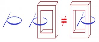
The magnetic core of the low-frequency transformer consists of steel plates. Using laminations instead of a solid core reduces eddy currents, which increases efficiency and reduces heat.
Magnetic cores of type 1, 2 or 3 are produced by stamping. Magnetic cores of types 4, 5 or 6 are produced by winding a steel tape onto a template, and magnetic cores of types 4 and 5 are then cut in half.
1, 4 – armored, 2, 5 – rod, 6, 7 – ring.
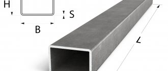
To determine the cross-section of the magnetic circuit, you need to multiply the dimensions “A” and “B”. For calculations in this article, the section size in centimeters is used.
Transformers with twisted rod position 1 and armored magnetic cores position 2.
Transformers with stamped armored magnetic cores, position 1, and core magnetic cores, position 2.
Transformers with twisted ring magnetic cores.
The overall power of a transformer can be approximately determined by the cross-section of the magnetic core. True, the error can be up to 50%, and this is due to a number of factors. The overall power directly depends on the design features of the magnetic core, the quality and thickness of the steel used, the size of the window, the amount of induction, the cross-section of the winding wire and even the quality of the insulation between the individual plates.
The cheaper the transformer, the lower its relative overall power. Of course, it is possible through experiments and calculations to determine the maximum power of a transformer with high accuracy, but there is not much point in this, since during the manufacture of the transformer, all this is already taken into account and reflected in the number of turns of the primary winding. So, when determining the power, you can be guided by the cross-sectional area of the set of plates passing through the frame or frames, if there are two of them.
Where:
P
– power in Watts,
B
– induction in Tesla,
S
– cross section in cm²,
1.69
– constant coefficient.
First, we determine the cross-section, for which we multiply the dimensions A and B.
Then we substitute the cross-sectional size into the formula and get the power. I chose 1.5Tc induction, since I have an armored twisted magnetic circuit.
If you need to determine the required cross-sectional area of the manipulator based on the known power, you can use the following formula:
It is necessary to calculate the cross-section of an armored stamped magnetic circuit for the manufacture of a 50-watt transformer.
The magnitude of induction can be found in the table. You should not use maximum induction values, as they can vary greatly for magnetic cores of different quality.
Maximum indicative values of induction.
HOW TO CALCULATE A STEP-DOWN TRANSFORMER.
In a household, it may be necessary to equip lighting in damp areas: basement or cellar, etc. These rooms have an increased risk of electric shock.
In these cases, you should use electrical equipment designed for a reduced supply voltage, no more than 42 volts. You can use a battery-powered electric flashlight or use a step-down transformer from 220 volts to 36 volts.
As an example, let's calculate and manufacture a single-phase 220/36 volt power transformer. To illuminate such rooms, a 36-volt electric light bulb with a power of 25-60 watts is suitable. Such light bulbs with a base for a standard socket are sold in electrical goods stores.
If you find a light bulb of a different power, for example 40 watts, there is nothing to worry about - that will do. It’s just that our transformer will be made with a power reserve.
Power in the secondary circuit: P2 = U2 • I2 = 60 watts
Where:
P2
is the power at the output of the transformer, we set 60 watts;
U2
is the voltage at the transformer output, we set it to 36 volts;
I2
is the current in the secondary circuit, in the load.
Transformer efficiency up to 100 watts
usually equal to no more than
η = 0.8
. Efficiency determines how much of the power consumed from the network goes to the load. The remainder goes to heating the wires and core. This power is irretrievably lost.
Let's determine the power consumed by the transformer from the network, taking into account losses:
Power is transferred from the primary winding to the secondary winding through the magnetic flux in the magnetic core. Therefore, the cross-sectional area of the magnetic circuit S depends on the value of P1, the power consumed from the 220 volt network.
The magnetic core is a W-shaped or O-shaped core made from sheets of transformer steel. The core will contain a frame with primary and secondary windings.
The cross-sectional area of the magnetic circuit is calculated by the formula:
Where:
S
is the area in square centimeters,
P1
is the power of the primary network in watts.
The value of
S
is used to determine the number of turns w per volt using the formula:
In our case, the cross-sectional area of the core is S = 10.4 cm2.
Let's calculate the number of turns in the primary and secondary windings.
Number of turns in the primary winding at 220 volts:
Number of turns in the secondary winding at 36 volts:
In load mode, there may be a noticeable loss of part of the voltage across the active resistance of the secondary winding wire. Therefore, for them it is recommended to take the number of turns 5-10% more than calculated. Let's take W2 = 180 turns.
The magnitude of the current in the primary winding of the transformer:
Current in the secondary winding of the transformer:
The diameters of the wires of the primary and secondary windings are determined by the values of the currents in them based on the permissible current density, the number of amperes per 1 square millimeter of conductor area. For transformers, the current density for copper wire is assumed to be 2 A/mm².
Read also: Makita saw chain
At this current density, the diameter of the wire without insulation in millimeters is determined by the formula:
For the primary winding, the wire diameter will be:
Wire diameter for secondary winding:
IF THERE IS NO WIRE OF THE REQUIRED DIAMETER, then you can take several thinner wires connected in parallel. Their total cross-sectional area must be no less than that corresponding to the calculated one wire.
The cross-sectional area of the wire is determined by the formula:
Where:
d is the diameter of the wire.
For example:
we could not find a wire for the secondary winding with a diameter of 1.1 mm.
The cross-sectional area of a wire with a diameter of 1.1 mm is equal to:
Let's round up to 1.0 mm².
From the table we select the diameters of two wires, the sum of the cross-sectional areas of which is equal to 1.0 mm².
For example, these are two wires with a diameter of 0.8 mm. and an area of 0.5 mm².
Or two wires:
- the first with a diameter of 1.0 mm. and a cross-sectional area of 0.79 mm², - the second with a diameter of 0.5 mm. and a cross-sectional area of 0.196 mm². which adds up to: 0.79 + 0.196 = 0.986 mm².
The coil is wound with two wires simultaneously; an equal number of turns of both wires is strictly maintained. The beginnings of these wires are connected to each other. The ends of these wires are also connected. It turns out like one wire with the total cross-section of two wires.
A power transformer is the simplest example of electrical energy conversion. Even with the constant improvement of radio-electronic devices and power supplies based on them, power supplies based on alternating voltage transformers do not lose their relevance.
Transformers for the power supply are large in size and weight, operate within a limited range of permissible input voltage, but are very easy to implement and are highly reliable and maintainable.
Types of magnetic cores
The basis of an AC transformer is a magnetic core, which must have certain magnetic properties. Transformers use steel of a special composition and with specific processing (transformer iron). During operation of the transformer, eddy currents are formed in the magnetic core, which heat the core and lead to a decrease in the efficiency of the transformer. To reduce eddy currents, the core is made not monolithic, but assembled from thin steel plates or strips coated with a non-conducting oxide layer.
Based on the type of metal used, cores are divided into:
The first type of cores is assembled in the form of a package of individual plates of the appropriate shape, and the second is wound from tape. In the future, the tape core can be cut into separate segments for ease of wire winding.
Cores are classified according to the type of magnetic circuit:
Each of the listed types may differ in the shape of the plates or segments:
The shape and type of the core in theory do not affect the calculation method, but in practice this should be taken into account when determining the efficiency and number of winding turns.
The ring (toroidal) core has the best properties. A transformer made on such a magnetic core will have maximum efficiency and minimum no-load current. This justifies the greatest labor intensity of winding, since at home this work is done exclusively by hand, without the use of a winding machine.
Initial data
The initial data on the basis of which the transformer is calculated are necessarily:
- Mains voltage;
- Voltage and number of secondary windings;
- Load consumption currents.
For a complete and accurate calculation of a step-down transformer, it is necessary to take into account the temperature regime, permissible deviations in the voltage of the primary winding and some other factors, however, practice shows that transformers manufactured according to simplified calculation data have fairly good parameters. Next we will tell you how to calculate a transformer without resorting to complex and cumbersome calculations.
Rewinding the stator of an angle grinder: do-it-yourself repair
- 26-01-2015
- 34
- 3560
Wholesale production of hand grinders began in the USSR in 1940. This device received the name “Bulgarian” due to the fact that it was first produced in the small Bulgarian town of Lovech, which had a patent for this invention.
Calculation procedure
The calculation of a power transformer begins with determining the overall power. To begin with, the total total power of all secondary windings is determined:
How to calculate the power of a transformer if the power of the windings is unknown? The formula known from the physics course will help you find out:
The overall power of the transformer is calculated from the total, taking into account the efficiency, which differs for devices of different power. The following indicative efficiency values have been established experimentally:
- Up to 50 W – 0.6 (60%);
- From 50 to 100 W – 0.7 (70%);
- From 100 to 150 W – 0.8 (80%).
A more powerful transformer will have an efficiency of 0.85.
Thus, the calculation of overall power looks like this:
Рг = efficiency∙Рс, where Рс – total power.
Based on the overall power of the transformer, the cross-sectional area of the magnetic circuit can be determined:
According to this formula, the required cross-sectional area is obtained in square centimeters. Based on the data obtained, a core with a similar or slightly larger cross-sectional value is selected. Using collapsible cores made of W and U shaped plates, you can change the thickness of the set within certain limits by adding or removing several plates.
How to determine the power of an unknown transformer? It is necessary to square the area of the core, expressed in square centimeters.
Note! The cross-section of the magnetic circuit should, if possible, have a shape close to a square.
After selecting the magnetic core, we calculate the winding data. Having a magnetic core and knowing its cross-sectional area, you can calculate the transformer windings (the number of turns in the windings). It is customary to take the number of turns per 1 V of voltage as the basis for the calculation, since this number is the same for all windings and depends on the characteristics of the magnetic circuit and the frequency of the supply voltage. The complete formula, which takes into account the network frequency and magnetic induction in the core, is very complex and is almost never used in calculations. Instead, a simplified version is used that takes into account only the material and design of the core:
Read also: Transformer for welding inverter
N=k/S, where k is a coefficient from the following list:
- W and P shaped magnetic circuit plates – k = 60;
- Tape core – k = 50;
- Toroidal magnetic circuit – k = 40.
As you can see, when using a toroidal core, the number of turns will be minimal.
Knowing the number of turns per volt, it is easy to determine the winding data of the windings for any voltage:
For the primary winding it will be:
Note! Since for step-down transformers the cross-section of the wire and the number of turns of the network winding are larger than all others, the ohmic losses in the wires will also be higher, therefore for low-power transformers (up to 100 W) these losses must be taken into account by increasing the number of turns of the primary winding by 5%.
If a rod-type transformer is being calculated, then usually the windings are divided in half and wound evenly on both rods. Parts of identical windings are then connected in series.
An equally important step in calculating a transformer is determining the cross-section of the winding conductors. Here, the value of current in the wires that causes minimal heating is taken as a basis. The higher the cross-section of the wire, the lower the current density per unit cross-section and, accordingly, the less heating. But an excessive increase in the cross-section of the winding wires leads to an increase in the mass of the transformer, an increase in cost, and also the likelihood that the windings simply will not fit into the windows of the magnetic circuit.
It is generally accepted that the optimal current density in windings is 4-7 A per 1 mm2. A lower density value is used to calculate the cross-section of the wires of the primary winding or any other that is closer to the core of the magnetic circuit. These windings have the worst cooling conditions.
In order not to operate with current densities and complex formulas for converting cross-sectional area to diameter, you can calculate the diameter using their simplified version:
- d = 0.7∙√I – for conductors of the primary winding;
- d = 0.6∙√I – for conductors of secondary windings.
For the windings, an insulated winding wire is used with a cross-section closest to the design one, but not less than it.
Important! The formula gives the calculated value for a bare wire, excluding insulation.
To measure the diameter of an unknown wire, a micrometer is needed. You can approximately determine the diameter by winding ten turns on a pencil and measuring the length of the winding.
To determine whether the windings will fit in the windows of the magnetic circuit, calculate the fill factor of the window:
K=0.008∙(d12 ∙w1+ d22 ∙w2+ d32 ∙w3+…)/Swindow.
If the resulting value is greater than 0.3, then the windings will not fit, and rewinding a half-finished device will not lead to a good result. There are several ways out:
- Use a magnetic core with a large cross-section;
- Increase the current density in the windings (no more than 5%);
- Reduce the number of turns in all windings at the same time (also no more than 5%).
Reducing the number of turns will lead to increased no-load current and losses in the transformer, which will be expressed in an increase in its temperature. Therefore, the use of the last two methods can only be recommended as a last resort.
How to measure wire diameter.
If you have a micrometer lying around at home, you can use it to measure the diameter of the wire.
It is better to first heat the wire in a match flame and only then remove the weakened insulation with a scalpel. If this is not done, then part of the copper can be removed along with the insulation, which will reduce the accuracy of the measurement, especially for a thin wire.
If you don’t have a micrometer, you can use an ordinary ruler. You need to wind 100 turns of wire around the tip of a screwdriver or another suitable axis, compress the turns with your fingernail and attach the resulting set to a ruler. Dividing the result by 100, we get the diameter of the wire with insulation. You can find out the diameter of the copper wire from the table below.
Example.
I wound 100 turns of wire and got a set length of -39 mm.
39 / 100 = 0.39 mm
Using the table, I determine the diameter of the copper wire - 0.35 mm.
Winding wire data table.
| Diameter without insulation, mm | Copper cross section, mm² | Resistance 1m at 20ºС, Ohm | Permissible load at current density 2A/mm² | Diameter with insulation, mm | Weight 100m with insulation, g |
| 0,03 | 0,0007 | 24,704 | 0,0014 | 0,045 | 0,8 |
| 0,04 | 0,0013 | 13,92 | 0,0026 | 0,055 | 1,3 |
| 0,05 | 0,002 | 9,29 | 0,004 | 0,065 | 1,9 |
| 0,06 | 0,0028 | 6,44 | 0,0057 | 0,075 | 2,7 |
| 0,07 | 0,0039 | 4,73 | 0,0077 | 0,085 | 3,6 |
| 0,08 | 0,005 | 3,63 | 0,0101 | 0,095 | 4,7 |
| 0,09 | 0,0064 | 2,86 | 0,0127 | 0,105 | 5,9 |
| 0,1 | 0,0079 | 2,23 | 0,0157 | 0,12 | 7,3 |
| 0,11 | 0,0095 | 1,85 | 0,019 | 0,13 | 8,8 |
| 0,12 | 0,0113 | 1,55 | 0,0226 | 0,14 | 10,4 |
| 0,13 | 0,0133 | 1,32 | 0,0266 | 0,15 | 12,2 |
| 0,14 | 0,0154 | 1,14 | 0,0308 | 0,16 | 14,1 |
| 0,15 | 0,0177 | 0,99 | 0,0354 | 0,17 | 16,2 |
| 0,16 | 0,0201 | 0,873 | 0,0402 | 0,18 | 18,4 |
| 0,17 | 0,0227 | 0,773 | 0,0454 | 0,19 | 20,8 |
| 0,18 | 0,0255 | 0,688 | 0,051 | 0,2 | 23,3 |
| 0,19 | 0,0284 | 0,618 | 0,0568 | 0,21 | 25,9 |
| 0,2 | 0,0314 | 0,558 | 0,0628 | 0,225 | 28,7 |
| 0,21 | 0,0346 | 0,507 | 0,0692 | 0,235 | 31,6 |
| 0,23 | 0,0416 | 0,423 | 0,0832 | 0,255 | 37,8 |
| 0,25 | 0,0491 | 0,357 | 0,0982 | 0,275 | 44,6 |
| 0,27 | 0,0573 | 0,306 | 0,115 | 0,31 | 52,2 |
| 0,29 | 0,0661 | 0.2bb | 0,132 | 0,33 | 60,1 |
| 0,31 | 0,0755 | 0,233 | 0,151 | 0,35 | 68,9 |
| 0,33 | 0,0855 | 0,205 | 0,171 | 0,37 | 78 |
| 0,35 | 0,0962 | 0,182 | 0,192 | 0,39 | 87,6 |
| 0,38 | 0,1134 | 0,155 | 0,226 | 0,42 | 103 |
| 0,41 | 0,132 | 0,133 | 0,264 | 0,45 | 120 |
| 0,44 | 0,1521 | 0,115 | 0,304 | 0,49 | 138 |
| 0,47 | 0,1735 | 0,101 | 0,346 | 0,52 | 157 |
| 0,49 | 0,1885 | 0,0931 | 0,378 | 0,54 | 171 |
| 0,51 | 0,2043 | 0,0859 | 0,408 | 0,56 | 185 |
| 0,53 | 0,2206 | 0,0795 | 0,441 | 0,58 | 200 |
| 0,55 | 0,2376 | 0,0737 | 0,476 | 0,6 | 216 |
| 0,57 | 0,2552 | 0,0687 | 0,51 | 0,62 | 230 |
| 0,59 | 0,2734 | 0,0641 | 0,547 | 0,64 | 248 |
| 0,62 | 0,3019 | 0,058 | 0,604 | 0,67 | 273 |
| 0,64 | 0,3217 | 0,0545 | 0,644 | 0,69 | 291 |
| 0,67 | 0,3526 | 0,0497 | 0,705 | 0,72 | 319 |
| 0,69 | 0,3739 | 0,0469 | 0,748 | 0,74 | 338 |
| 0,72 | 0,4072 | 0,043 | 0,814 | 0,78 | 367 |
| 0,74 | 0,4301 | 0,0407 | 0,86 | 0,8 | 390 |
| 0,77 | 0,4657 | 0,0376 | 0,93 | 0,83 | 421 |
| 0,8 | 0,5027 | 0,0348 | 1,005 | 0,86 | 455 |
| 0,83 | 0,5411 | 0,0324 | 1,082 | 0,89 | 489 |
| 0.86 | 0,5809 | 0,0301 | 1,16 | 0,92 | 525 |
| 0,9 | 0,6362 | 0,0275 | 1,27 | 0,96 | 574 |
| 0,93 | 0,6793 | 0,0258 | 1,36 | 0,99 | 613 |
| 0,96 | 0,7238 | 0,0242 | 1,45 | 1,02 | 653 |
| 1 | 0,7854 | 0,0224 | 1,57 | 1,07 | 710 |
| 1,04 | 0,8495 | 0,0206 | 1,7 | 1,12 | 764 |
| 1,08 | 0,9161 | 0,0191 | 1,83 | 1,16 | 827 |
| 1,12 | 0,9852 | 0,0178 | 1,97 | 1,2 | 886 |
| 1,16 | 1,057 | 0,0166 | 2,114 | 1,24 | 953 |
| 1,2 | 1,131 | 0,0155 | 2,26 | 1,28 | 1020 |
| 1,25 | 1,227 | 0,0143 | 2,45 | 1,33 | 1110 |
| 1,3 | 1,327 | 0,0132 | 2,654 | 1,38 | 1190 |
| 1,35 | 1,431 | 0,0123 | 2,86 | 1,43 | 1290 |
| 1,4 | 1,539 | 0,0113 | 3,078 | 1,48 | 1390 |
| 1,45 | 1,651 | 0,0106 | 3,3 | 1,53 | 1490 |
| 1,5 | 1,767 | 0,0098 | 3,534 | 1,58 | 1590 |
| 1,56 | 1,911 | 0,0092 | 3,822 | 1,64 | 1720 |
| 1,62 | 2,061 | 0,0085 | 4,122 | 1,71 | 1850 |
| 1,68 | 2,217 | 0,0079 | 4,433 | 1,77 | 1990 |
| 1,74 | 2,378 | 0,0074 | 4,756 | 1,83 | 2140 |
| 1,81 | 2,573 | 0,0068 | 5,146 | 1,9 | 2310 |
| 1,88 | 2,777 | 0,0063 | 5,555 | 1,97 | 2490 |
| 1,95 | 2,987 | 0,0059 | 5,98 | 2,04 | 2680 |
| 2,02 | 3,205 | 0,0055 | 6,409 | 2,12 | 2890 |
| 2,1 | 3,464 | 0,0051 | 6,92 | 2,2 | 3110 |
| 2,26 | 4,012 | 0,0044 | 8,023 | 2,36 | 3620 |
| 2,44 | 4,676 | 0,0037 | 9,352 | 2,54 | 4220 |
Return to top menu
Making windings
The transformer windings are made on a frame made of insulating material. The frame can be solid or collapsible. Despite its apparent complexity, a collapsible frame is easier to make, and its dimensions can be easily calculated to fit any existing core. From the materials for the frame, you can take sheet getinax, textolite or fiberglass. In the cheeks of the frame you need to provide holes for the leads.
The winding terminals are made with flexible stranded wire, carefully insulating the soldering area. The winding itself is carried out, if possible, turn to turn. Such winding allows better use of free space, reduces wire consumption, and most importantly, at the intersections of wires, if the winding is poorly executed, there is a risk of damage to the insulation and interturn short circuits. This rule does not apply to thin wire with a diameter of less than 0.2 mm, since it is very difficult to carry out an ordinary winding on it at home.
Each winding must be insulated from one another, especially the primary winding. For insulation, you can use several layers of FUM tape. It is made of fluoroplastic, which has good electrical insulating properties.
Important! FUM tape has a small thickness, and fluoroplastic has fluidity, so you need to make several layers of insulation.
Table of volts per turn
In order not to constantly carry out calculations, you can use the table, which shows the average data of the windings depending on the power:
| Power, P | Section in cm2, S | Number of vit. /B, W | Power, P | Section in cm2, S | Number of vit. /B, W |
| 1 | 1.4 | 32 | 50 | 9.0 | 5.0 |
| 2 | 2.1 | 21 | 60 | 9.8 | 4.6 |
| 5 | 3.6 | 13 | 70 | 10.3 | 4.3 |
| 10 | 4.6 | 9.8 | 80 | 11.0 | 4.1 |
| 15 | 5.5 | 8.4 | 90 | 11.7 | 3.9 |
| 20 | 6.2 | 7.3 | 100 | 12.3 | 3.7 |
| 25 | 6.6 | 6.7 | 120 | 13.4 | 3.4 |
| 30 | 7.3 | 6.2 | 150 | 15.0 | 3.0 |
| 40 | 8.3 | 5.4 | 200 | 17.3 | 2.6 |
Transformer assembly
The quality of the transformer largely depends on the correct assembly of the magnetic circuit. When assembling the W-shaped armor core, adjacent plates must be laid alternately in different directions. The plate pack should be stacked as tightly as possible. After assembly, it must be tightened tightly with screws. A loose transformer makes a lot of noise during operation. Particular attention should be paid to the tight fit of the W-shaped plates with the floor plates. The gap between them will lead to the core becoming open-circuited, and this implies the following:
- Increased no-load current;
- Decrease in efficiency;
- Increased magnetic scattering field.
When assembling a split strip core, you need to pay attention to the fit of the parts to each other, since during manufacturing they are adjusted by grinding. To reduce noise, the ends of the plate packages can be coated with a layer of varnish.
Read also: Assembling an electrical panel for a private house 380V 15kW
Note! Parts of the tape magnetic circuit require careful handling, since delaminated tapes are almost impossible to install in their original place. The plates of the collapsible core cannot be bent or subjected to impacts, as this will disrupt the structure of the metal and it will lose its properties. As a last resort, plates bent at a large radius must be carefully bent by hand and, when assembled, placed in the middle of the plate pack. With further screeding they will align.
Calculating a network transformer is not difficult. It is more important to determine the requirements for it. The accuracy of further calculations will depend on the correctness of the task. For a power transformer, the calculation can also be conveniently performed using an online calculator. The step-up transformer is calculated using the same method.
Video
The simplest calculation of a power transformer allows you to find the cross-section of the core, the number of turns in the windings and the diameter of the wire. The alternating voltage in the network is 220 V, less often 127 V and very rarely 110 V. For transistor circuits, a constant voltage of 10 - 15 V is needed, in some cases, for example, for powerful output stages of low-frequency amplifiers - 25 ÷ 50 V. To power the anode and screen circuits of electronic lamps most often use a constant voltage of 150 - 300 V, to power the incandescent circuits of lamps an alternating voltage of 6.3 V. All voltages necessary for any device are obtained from one transformer, which is called a power transformer.
The power transformer is made on a collapsible steel core from thin W-shaped, less often U-shaped plates isolated from each other, as well as hollowed-out strip cores of the ShL and PL types (Fig. 1).
Its dimensions, or more precisely, the cross-sectional area of the middle part of the core, are selected taking into account the total power that the transformer must transmit from the network to all its consumers.
A simplified calculation establishes the following relationship: the cross-section of the core S in cm², squared, gives the total power of the transformer in W.
For example, a transformer with a core having sides of 3 cm and 2 cm (Sh-20 type plates, set thickness 30 mm), that is, with a core cross-sectional area of 6 cm², can consume 36 W of power from the network and “process” it. This simplified calculation gives quite acceptable results. And vice versa, if a power of 36 W is needed to power an electrical device, then taking the square root of 36, we find out that the cross-section of the core should be 6 cm².
For example, it should be assembled from Sh-20 plates with a set thickness of 30 mm, or from Sh-30 plates with a set thickness of 20 mm, or from Sh-24 plates with a set thickness of 25 mm, and so on.
The core cross-section must be matched to the power so that the core steel does not fall into the magnetic saturation region. And hence the conclusion: the cross-section can always be taken in excess, say, instead of 6 cm², take a core with a cross-section of 8 cm² or 10 cm². It won't get any worse. But it is no longer possible to take a core with a cross-section smaller than the calculated one, since the core will fall into the saturation region, and the inductance of its windings will decrease, their inductive resistance will drop, the currents will increase, the transformer will overheat and fail.
A power transformer has several windings. Firstly, network, connected to a network with a voltage of 220 V, it is also primary.
In addition to the network windings, a network transformer can have several secondary windings, each with its own voltage. A transformer for powering tube circuits usually has two windings - a 6.3 V filament winding and a step-up winding for the anode rectifier. In a transformer for powering transistor circuits, there is most often one winding that powers one rectifier. If a reduced voltage needs to be supplied to any stage or circuit node, it is obtained from the same rectifier using a quenching resistor or voltage divider.
The number of turns in the windings is determined by an important characteristic of the transformer, which is called the “number of turns per volt,” and depends on the cross-section of the core, its material, and the grade of steel. For common types of steel, you can find the "number of turns per volt" by dividing 50-70 by the cross-section of the core in cm:
So, if you take a core with a cross-section of 6 cm², then the “number of turns per volt” will be approximately 10.
The number of turns of the primary winding of the transformer is determined by the formula:
This means that the primary winding at a voltage of 220 V will have 2200 turns.
The number of turns of the secondary winding is determined by the formula:
If a 20 V secondary winding is needed, it will have 240 turns.
Now we select the winding wire. For transformers, copper wire with thin enamel insulation (PEL or PEV) is used. The wire diameter is calculated based on low energy losses in the transformer itself and good heat dissipation using the formula:
If you take a wire that is too thin, then, firstly, it will have high resistance and generate significant thermal power.
So, if we take the primary winding current to be 0.15 A, then the wire needs to be 0.29 mm.
Alternative method for dimensions
The approximate parameters of the transformer, based on the available core, can be determined in another way, and then conclusions can be drawn about the possibility of further use.
Knowing the cross-sectional area of the magnetic circuit in square centimeters, you can estimate the maximum power that this converter is capable of providing:
PG=S2
It should be borne in mind that this power is dimensional, and the real one will have a smaller value:
P=0.8 PG
Usually, provided that the calculated power matches the required one, the primary winding connected to the 220 V network can be left untouched, recalculating only the parameters at the outputs.