In order to calculate the electrical network for voltage loss, it is necessary to know the parameters of the lines, namely their resistance and conductivity. If calculations are made for DC circuits, then it is quite enough to know only the ohmic resistance of the line. But when calculating an AC line, ohmic resistance alone is not enough, and in addition to active resistances, it is also necessary to know the inductive reactances and capacitive conductivities of wires and cables.
Active resistance of wires and cables
It is known from electrical engineering that the total resistance under equal conditions to alternating and direct current will differ. This also applies to wires and cables. This is due to the fact that the alternating current is distributed unevenly across the cross section (surface effect). However, for wires made of non-ferrous metals and with an alternating voltage frequency of 50 Hz, this effect does not have too much influence and can be neglected. Thus, when calculating conductors made of non-ferrous metals, their resistance to alternating and direct current is assumed to be equal.
In practice, the active resistance of copper and aluminum conductors is calculated using the formula:
Where: l is the length in km, γ is the specific conductivity of the wire material m/ohm∙mm2, r0 is the active resistance of 1 km of wire per phase Ohm/km, s is the cross-sectional area, mm2.
The value of r0 is usually taken from reference tables.
The active resistance of the wire is also affected by the ambient temperature. The value of r0 at temperature Θ can be determined by the formula:
Where: α – temperature coefficient of resistance; r20 – active resistance at a temperature of 20 0С, γ20 – specific conductivity at a temperature of 20 0С.
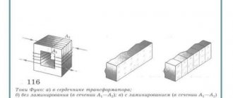
Steel wires have significantly higher active resistance than similar wires made of non-ferrous metals. Its increase is due to a significantly lower specific conductivity and the surface effect, which is much more pronounced in steel wires than in aluminum or copper. Moreover, in steel wires there are losses of active energy due to eddy currents and magnetization reversal, which is taken into account in equivalent circuits of lines as an additional component of active resistance.
The active resistance of steel wires (unlike wires made of non-ferrous metals) strongly depends on the amount of current flowing, so it is impossible to use a constant value of specific conductivity in calculations.
It is very difficult to analytically express the active resistance of steel wires depending on the flowing current, so special tables are used to determine it.
Copper resistivity
Home > Theory > Copper resistivity
One of the most common metals for making wires is copper. Its electrical resistance is the lowest among affordable metals. It is less only for precious metals (silver and gold) and depends on various factors.
Formula for calculating conductor resistance
What is electric current
At different poles of a battery or other current source there are opposite electric charge carriers. If they are connected to a conductor, charge carriers begin to move from one pole of the voltage source to the other. These carriers in liquids are ions, and in metals they are free electrons.
Definition. Electric current is the directed movement of charged particles.
Resistivity
Electrical resistivity is a value that determines the electrical resistance of a reference sample of a material. The Greek letter “p” is used to denote this quantity. Formula for calculation:
p=(R*S)/l.
This value is measured in Ohm*m. You can find it in reference books, in resistivity tables or on the Internet.
Free electrons move through the metal within the crystal lattice. Three factors influence the resistance to this movement and the resistivity of the conductor:
- Material. Different metals have different atomic densities and numbers of free electrons;
- Impurities. In pure metals the crystal lattice is more ordered, therefore the resistance is lower than in alloys;
- Temperature. Atoms are not stationary in their places, but vibrate. The higher the temperature, the greater the amplitude of vibrations, which interferes with the movement of electrons, and the higher the resistance.
In the following figure you can see a table of the resistivity of metals.
Metal resistivity
Interesting. There are alloys whose electrical resistance drops when heated or does not change.
Conductivity and electrical resistance
Since cable dimensions are measured in meters (length) and mm² (section), the electrical resistivity has the dimension Ohm mm²/m. Knowing the dimensions of the cable, its resistance is calculated using the formula:
R=(p*l)/S.
In addition to electrical resistance, some formulas use the concept of “conductivity”. This is the reciprocal of resistance. It is designated “g” and is calculated using the formula:
g=1/R.
Conductivity of liquids
The conductivity of liquids is different from the conductivity of metals. The charge carriers in them are ions. Their number and electrical conductivity increase when heated, so the power of the electrode boiler increases several times when heated from 20 to 100 degrees.
Interesting. Distilled water is an insulator. Dissolved impurities give it conductivity.
Electrical resistance of wires
The most common metals for making wires are copper and aluminum. Aluminum has a higher resistance, but is cheaper than copper. The resistivity of copper is lower, so the wire cross-section can be chosen smaller. In addition, it is stronger, and flexible stranded wires are made from this metal.
The following table shows the electrical resistivity of metals at 20 degrees. In order to determine it at other temperatures, the value from the table must be multiplied by a correction factor, different for each metal. You can find out this coefficient from the relevant reference books or using an online calculator.
Wire resistance
Selection of cable cross-section
Because a wire has resistance, when electric current passes through it, heat is generated and a voltage drop occurs. Both of these factors must be taken into account when choosing cable cross-sections.
Selection by permissible heating
When current flows in a wire, energy is released. Its quantity can be calculated using the electric power formula:
P=I²*R.
In a copper wire with a cross section of 2.5 mm² and a length of 10 meters R = 10 * 0.0074 = 0.074 Ohm. At a current of 30A P=30²*0.074=66W.
This power heats the conductor and the cable itself. The temperature to which it heats up depends on the installation conditions, the number of cores in the cable and other factors, and the permissible temperature depends on the insulation material. Copper has greater conductivity, so the power output and the required cross-section are lower. It is determined using special tables or using an online calculator.
Table for selecting wire cross-section based on permissible heating
Permissible voltage loss
In addition to heating, when electric current passes through the wires, the voltage near the load decreases. This value can be calculated using Ohm's law:
U=I*R.
Reference. According to PUE standards, it should be no more than 5% or in a 220V network - no more than 11V.
Therefore, the longer the cable, the larger its cross-section should be. You can determine it using tables or using an online calculator. In contrast to the choice of cross-section based on permissible heating, voltage losses do not depend on laying conditions and insulation material.
In a 220V network, voltage is supplied through two wires: phase and neutral, so the calculation is made using double the length of the cable. In the cable from the previous example it will be U=I*R=30A*2*0.074Ohm=4.44V. This is not much, but with a length of 25 meters it turns out to be 11.1V - the maximum permissible value, you will have to increase the cross-section.
Maximum permissible cable length of a given section
Electrical resistance of other metals
In addition to copper and aluminum, other metals and alloys are used in electrical engineering:
- Iron. Steel has a higher resistivity, but is stronger than copper and aluminum. Steel strands are woven into cables designed to be laid through the air. The resistance of iron is too high to transmit electricity, so the core cross-sections are not taken into account when calculating the cross-section. In addition, it is more refractory, and leads are made from it for connecting heaters in high-power electric furnaces;
- Nichrome (an alloy of nickel and chromium) and fechral (iron, chromium and aluminum). They have low conductivity and refractoriness. Wirewound resistors and heaters are made from these alloys;
- Tungsten. Its electrical resistance is high, but it is a refractory metal (3422 °C). It is used to make filaments in electric lamps and electrodes for argon-arc welding;
- Constantan and manganin (copper, nickel and manganese). The resistivity of these conductors does not change with changes in temperature. Used in high-precision devices for the manufacture of resistors;
- Precious metals – gold and silver. They have the highest specific conductivity, but due to their high price, their use is limited.
Inductive reactance
Formulas for calculating the conductivity of wires are valid only in a direct current network or in straight conductors at low frequencies. Inductive reactance appears in coils and in high-frequency networks, many times higher than usual. In addition, high frequency current only travels along the surface of the wire. Therefore, it is sometimes coated with a thin layer of silver or Litz wire is used.
Reference. Litz wire is a stranded wire, each core in which is isolated from the rest. This is done to increase surface area and conductivity in high frequency networks.
Copper's resistivity, flexibility, relatively low price and mechanical strength make this metal, along with aluminum, the most common material for making wires.
Video
elquanta.ru
Inductive reactance of wires and cables
To determine the inductive reactance (denoted by X) of a cable or overhead line of a certain length in kilometers, it is convenient to use the expression:
Where: X0 is the inductive reactance of one kilometer of wire or cable per phase, Ohm/km.
X of one kilometer of overhead or cable line can be determined by the formula:
Where: Dav – average distance between wires or centers of cable cores, mm; d – diameter of the current-carrying cable core or wire diameter, mm; μt – relative magnetic permeability of the wire material;
The first term on the right side of the equation is due to the external magnetic field and is called external inductive reactance X0/. From this expression it is clear that X0/ depends only on the distance between the wires and their diameter, and since the distance between the wires is selected based on the rated line voltage, accordingly X0/ will increase with increasing rated line voltage. X0/ there are more overhead lines than cable lines. This is due to the fact that the current-carrying wires of the cable are located much closer to each other than the wires of overhead lines.
For one phase:
Where: D1:2 is the distance between the wires.
For a single three-phase line with wires arranged in a triangle:
When the wires of a three-phase line are located horizontally or vertically in the same plane:
An increase in the cross-section of the line wires leads to a slight decrease in X0/.
The second term in the equation for determining X0 is due to the magnetic field inside the conductor. It expresses the internal inductive reactance X0//.
Thus, the expression for X0 can be represented as:
For lines made of non-magnetic materials μ = 1, the internal inductive reactance X0// compared to the external X0/ is negligible, so it is very often neglected.
In this case, the formula for determining X0 will take the form:
For practical calculations, the inductive resistance of cables and wires is determined using the corresponding tables.
In the case of approximate calculations, it can be considered that for overhead lines with a voltage of 6-10 kV X0 = 0.3 - 0.4 Ohm/km, and for cable lines X0 = 0.08 Ohm/km.
The internal inductive reactance of steel wires is very different from X0// wires made of non-ferrous metals. This is due to the fact that X0// is proportional to the magnetic permeability μr, which strongly depends on the magnitude of the current in the wire. If for wires made of non-ferrous metals μr = 1, then for steel wires μr can reach a value of 103 and even higher.
X0// for lines laid with steel wires cannot be neglected. As a rule, this value is taken from tables compiled on the basis of experimental data.
Resistances r0 and X0// at certain current values can reach maximum values, and then decrease with increasing current. This phenomenon is explained by the magnetic saturation of steel.
Resistance of cables with paper, rubber and polyvinyl chloride insulation for voltage 6 - 35 kV
1. RD 153-34.0-20.527-98 – Guidelines for the calculation of short circuit currents and the selection of electrical equipment. 2002 Table P.8, page 145.
2. Design of cable networks and wiring. Khromchenko G.E. 1980 Table 2-5, page 48.
3. Handbook for power supply design. SOUTH. Barybina. 1990 Table 2.63, pages 175-176.
4. Electrician's reference book. Grigorieva V.I. 2004 Tables 3.9.7; 3.9.11; pages 448-449
If you did not find the values of active and reactive resistance of the cables in the tables provided. In this case, the cable resistance can be determined using the given formulas with the actual parameters of the cables substituted into them.
The calculation method is presented in the book: “Design of cable networks and wiring. Khromchenko G.E. 1980, pages 45-48."
Cable resistance
1. The active resistance of a single-wire core is determined by formula 2-1, Ohm:
Where:
- l—core length, m;
- s – cross-section of the core, mm2, determined by the formula: π*d2/4;
- d – cable core diameter;
- α20 – temperature coefficient of resistance, equal at 20 °C:
- 0.00393 1/deg – for copper;
- 0.00403 1/deg – for aluminum;
- ρ20 – resistivity of the core material at 20 °C (core manufacturing temperature), can be taken according to the book “Electrician’s Reference Book. Grigorieva V.I. 2004" Table 1.14, page 30.
- tl – permissible core heating temperature, according to PUE clauses 1.3.10 and 1.3.12.
2. The active resistance of a stranded conductor is also determined by formula 2-1, but due to the design features of the stranded conductor, instead of the values of ρ20, ρр is entered into the formula equal to:
- 0.0184 Ohm*mm2/m – for copper conductors;
- 0.031 Ohm*mm2/m – for aluminum conductors.
3. Specific active resistance of the core, per unit line length of 1 km, is determined from the following dependencies, Ohm/km:
Cable inductance
1. The specific reactive (inductive) resistance of the cable is determined by the formula 2-8, Ohm/km:
Where:
- d – cable core diameter.
- lср – the average geometric distance between the centers of the cable cores is determined by the formula [L1.p.19]:
Where:
- lА-В - distance between the centers of the cores of phases A and B;
- lВ-С - distance between the centers of the cores of phases B and C;
- lС-А is the distance between the centers of the cores of phases C and A.
Example
Determine the active and inductive resistance of the cable brand AVVGng(A)-LS 3x120 for a voltage of 6 kV produced by Elektrokabel Kolchuginsky Plant. Cable line length L = 300 m.
Solution
1. Determine the cross-section of the cable conductor having a round shape:
S = π*d2/4 = 3.14*13.52/4 = 143 mm2
The calculation of the cross-section of the sector core, as well as the dimensions of the sector cores for voltages of 0.4 - 10 kV, is presented in the article: “Calculation of the cross-section of the sector cable core.”
where: d = 13.5 mm is the diameter of the cable core (multi-wire compacted cores), determined according to GOST 22483-2012 table C.3 for a cable with a conductive core of class 2. The class of the conductive core is indicated in the catalog of the cable manufacturer.
Below is the classification of cable cores, according to GOST 22483-2012:
2. Determine the specific active resistance of the AVVGng(A)-LS 3x120 cable, per unit line length of 1 km, Ohm/km:
Where:
- l = 1000 m – core length, m;
- α20 – temperature coefficient of resistance, equal at 20 °C:
- 0.00393 1/deg – for copper;
- 0.00403 1/deg – for aluminum;
- ρр – resistivity of the material of the stranded core, equal to:
- 0.0184 Ohm*mm2/m – for copper conductors;
- 0.031 Ohm*mm2/m – for aluminum conductors;
- tl = 65 °C - permissible heating temperature of the core, for a cable with a voltage of 6 kV, according to the PUE clause 1.3.10.
3. We determine the specific active resistance of the cable based on the length of the cable route:
where: L = 0.3 km – length of the cable route, km;
4. Determine the average geometric distance between the centers of the cable cores, taking into account that the cable cores are arranged in the form of a triangle.
Where:
- lА-В = 20.3 mm - the distance between the centers of the cores of phases A and B;
- lВ-С = 20.3 mm - distance between the centers of the cores of phases B and C;
- lС-А = 20.3 mm - the distance between the centers of the cores of phases C and A.
To determine the distance between the centers of the cable cores, you need to know the diameter of the cable cores d = 13.5 mm and the thickness of the insulation of the polyvinyl chloride plastic cores dи.ж = 3.4 mm, according to GOST 16442-80 table 4. Determine the distance between the centers of the phase cores equal to 20.3 mm (see Fig. 1).
5. Determine the specific reactive (inductive) resistance of cable brand AVVGng(A)-LS 3x120, Ohm/km:
where: d = 13.5 mm – cable core diameter;
6. We determine the specific reactance of the cable based on the length of the cable route:
Capacitive conductivity of lines
Electric lines, in addition to active and inductive resistance, are also characterized by capacitive conductivity, which is due to the capacitance between the wires and between the wires and the ground.
The value of the working capacitance in a three-phase overhead line can be approximately determined by the formula:
From this formula it is clear that the working capacity will increase with an increase in the cross-section of the wires and a decrease in the distance between them. Therefore, with equal cross-sections of current-carrying parts, low-voltage lines have a greater working capacity than high-voltage lines. Due to the small distances between the current-carrying conductors of the cable and the greater dielectric constant of the insulation compared to air, the working capacity of the cable line is significantly greater than the capacity of the overhead line.
The capacitive conductivity of a single-circuit overhead line is determined by the formula:
Determining the working capacitance of a cable line using formulas that include the dielectric constant of the cable insulation, geometric dimensions and other design features is not an easy task, therefore the values of the working capacitance are determined using special tables compiled by the manufacturer for various brands of cables, depending on their nominal voltage.
The capacitive current at the beginning of the line at idle (with electrical receivers turned off) can be determined from the formula:
Where: U – line voltage of the network, V; l – line length, km;
Capacitive currents are of serious importance in overhead lines with operating voltages of 110 kV and above and in cable lines with voltages above 10 kV. When calculating electrical networks with voltages lower than those listed above, the line capacitance may not be taken into account. The capacitance of the conductive parts of the line in relation to the ground is important when calculating grounding devices and protection.
In a network with an isolated neutral, the magnitude of the capacitive current of a single-phase ground fault can be approximately determined by the formulas:
- For overhead line:
- For cable line:
Introduction
IEC 60228:2004 specifies requirements for the nominal conductor cross-sectional area of electrical cables, wires and cords of a wide range of types, including requirements for the number and diameter of wires and electrical resistance values. IEC 60228:2004 sets requirements for the design of conductors only for power cables and cords (see section 1), therefore it contains only conductor classes 1, 2, 5 and 6. Currently, a large number of cable products with conductors of classes 3 have been developed in the CIS countries and 4, therefore this standard is supplemented with these classes and the word “power” is excluded from section 1. The requirements for the conductors of electrical cables, wires and cords in this standard fully comply with those established in IEC 60228:2004. At the same time, this standard expands the requirements of IEC 60228:2004 to all groups of cable products, and also maintains the ranges of core cross-sections by class; for class 1, the production of aluminum cores and the possibility of producing multi-wire cores along with single-wire cores are retained. The core sizes given in this standard are in the metric system. Currently, Canada uses the American AWG (American Wire Gauge) and kcmil (kilo circular mils) systems for larger sizes to indicate conductor sizes and parameters, as shown below. Use in Canada of this size range is required by national electrical codes. IEC cable standards do not include cables, wires or cords with AWG/kcmil conductors.
| AWG | kcmil | ||||||
| Core size | Nominal core cross-section, mm | Core size | Nominal core cross-section, mm | Core size | Nominal core cross-section, mm | Core size | Nominal core cross-section, mm |
| — | — | — | — | 250 | 127 | 750 | 380 |
| — | — | — | — | 300 | 152 | 800 | 405 |
| 20 | 0,519 | 4 | 21,2 | 350 | 177 | 900 | 456 |
| 18 | 0,823 | 3 | 26,7 | 400 | 203 | 1000 | 507 |
| 16 | 1,31 | 2 | 33,6 | 450 | 228 | 1200 | 608 |
| 14 | 2,08 | 1 | 42,4 | 500 | 253 | 1250 | 633 |
| 12 | 3,31 | 1/0 | 53,5 | 550 | 279 | 1500 | 760 |
| 10 | 5,26 | 2/0 | 67,4 | 600 | 304 | 1750 | 887 |
| 8 | 8,37 | 3/0 | 85,0 | 650 | 329 | 2000 | 1010 |
| 6 | 13,3 | 4/0 | 107 | 700 | 355 | — | — |