Even the simplest repair of an angle grinder in a service workshop can cost from a third to half of its cost. Therefore, before turning to professionals, you should always try to fix it yourself. Moreover, the passports of Bulgarian women often contain tables of the most common faults and the reasons for their occurrence. For home repairs, in most cases, you can get by with a set of the most common tools: screwdrivers, pliers, wrenches and a multimeter. The only time mandrels, pullers, or similar devices may be required is when removing and installing bearings. And spare parts for repairing an angle grinder can be purchased without any problems in well-known online stores.
General rules for repairing power tools
The safety rules for repairing an angle grinder are the same as for repairing any other power tool. Cleaning from dust, disassembling and assembling is carried out only with the device completely de-energized. Repair work must be carried out on a dielectric surface, and the power source must be equipped with a short circuit protection circuit breaker. It is strictly forbidden to manually turn the angle grinder spindle if the power supply is turned on. It is also prohibited to carry out test runs during or after repair with a cutting disc installed on the spindle.
How to extend the life of a microwave
In order for your microwave oven to serve you for many years, you need to periodically pay attention to it and follow generally accepted rules:
- Wash and remove dirt.
- Do not operate an empty microwave oven.
- Do not place metal utensils or metal plates inside the appliance.
- Inspect the device for damage to the enamel.
- To avoid splashing of fat, you need to cover food plates with a special lid.
- Do not place large dishes in the microwave as they may damage the enamel.
READ How to Sharpen Skates with a Grinder Video
Devices, like people, need attention and care. Use the microwave oven correctly: only for its intended purpose and in accordance with the instructions. Then the device will please you with long-term good work.
Source
Today on sale you can find various power tools that differ from each other in their functions, purpose and cost. But the angle grinder (angle grinder or grinder) is especially popular among buyers. But what kind of tool this is and how to work with it, we will talk in this article.
Operating principle
The operation of this tool is based on the rotation of a nozzle, which can act as a disk or a special brush. The mechanism is controlled by electricity.
Common problems in the operation of angle grinders
The grinder is a fairly unpretentious tool, as it is designed to work with high loads and in dusty environments. The main problems in its operation in most cases are associated with improper operation, as well as non-compliance with maintenance and scheduled repairs. The most common malfunctions are:
- The angle grinder does not turn on. The most common reason for this phenomenon is a broken wire in the power cable or a faulty switch. And for grinders with electronic control, the speed control unit or soft start fails.
- The grinder operates at low speeds. As a rule, this is due to an interturn short circuit in the rotor windings or an electronic malfunction.
- The angle grinder gets very hot. This often occurs due to a violation of the ratio of recommended work cycles and breaks. In addition, heating may be a result of poor engine cooling due to dust accumulated inside the housing.
- The grinder sparkles. In this case, the main reasons are wear of the carbon brushes or wear of the electric motor commutator. Brushes also spark when there is increased contamination and oxidation of the commutator plates.
- The Bulgarian smokes. This is usually observed when the unit is used too intensively and the air cooling ducts are filled with dust. The reason that the tool smokes can also be short circuits in the rotor or stator windings.
- The angle grinder hums, but does not rotate. As a rule, this happens when the gears of the gearbox jam or the bearings fail.
- The spindle lock button is broken. The reason for this is that dust gets inside the clamp, causing wear on its rod.
- The bearings are broken. Bearing failure most often occurs after prolonged use and work with shock loads.
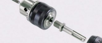
Another fairly common problem with angle grinders is the jamming of the clamping nut.
Collector faults
During intensive use, the brushes develop an annular depression underneath them on the commutator. It negatively affects their work. For powerful engines, you have to remove the armature, install it in a lathe and grind the manifold, aligning it. But for household electrical appliances, such an operation is not economically justified - it is easier to buy new equipment. In addition, the wear of the collector will affect itself in a few years, when the electrical appliance becomes obsolete, and the new device will be more functional.
Collector with worn lamellas
In domestic conditions, the collector can only be cleaned. To do this, use very fine sandpaper. She wraps herself around the collector and presses it tightly with her hand. Cleaning is done by rotating the collector in different directions, periodically changing position.
General instructions for disassembling an angle grinder
All angle grinders consist of two main parts: a plastic drive housing and a metal gearbox. In addition, for many angle grinders you can separately disassemble the rear handle, inside of which there is a power input, as well as control system units. To repair an angle grinder at home, you may need Phillips and flathead screwdrivers, wrenches and thin pliers. In addition, to check and repair electrical circuits, you will need a multimeter and tools for working with wires. Before disassembling the grinder, it is necessary to remove the cutting disc and protective casing.
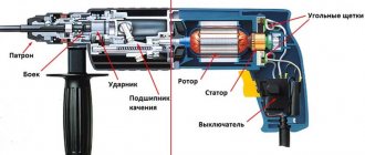
Operating principle and main parts of the grinder + (Video)
Any, even very complex mechanism, consists of large and small parts. Bulgarian is no exception. Its main components and parts:
- Frame;
- Stator;
- Rotor;
- Gearbox;
- Connecting wire;
- Switch.
Units can be divided into electrical and mechanical. Electrical - stator, rotor, connecting wire. Mechanical – housing and gearbox. Of course, there is also a button, a fork, and brushes.
The armature (rotor) consists of:
- Vala;
- Windings;
- Contact collector;
- Brush holder and brushes;
- Ball bearings.
For repairs, you will need a minimum amount of tools - a regular screwdriver and with a special bit, pliers, a multimeter, electrical tape, and thick lubricant for gearboxes. If we have all this, then we can start repairing it ourselves.
Step-by-step electrical diagnostics with a multimeter or light bulb
When diagnosing and repairing the electrical part of an angle grinder, it is most convenient to use a multifunction tester (abbreviated name - multimeter). If such a device is not at hand, then a screwdriver with an indicator or a light bulb with two wires will be suitable for some checks. During the repair process, the multimeter allows you to measure both voltage and current values, as well as the resistance of the motor windings. The indicator and light bulb can only show the presence or absence of voltage.
Diagnosis of power failure
Perhaps the most common malfunction of an angle grinder's electrical equipment is a break in the power wires inside the power cable sheath. To diagnose and repair such damage, it is enough to disassemble the rear handle of the angle grinder and check the voltage at the terminals in front of the switch. Another way is to disconnect the cable terminals and use a multimeter to check the resistance of each wire for an open.
Checking the stator and rewinding it
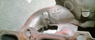
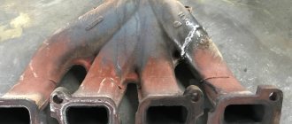
To check the stator of the electric motor of the angle grinder, you need to disconnect both of its windings from the power circuit, and then measure their resistance with a multimeter in the range of 200 Ohms. On a working winding, the device will show a resistance of about one ohm, and on a faulty winding (with a break) - tens or hundreds of ohms. If the winding fails as a result of a short circuit, carbon deposits can usually be seen on the inside of the stator housing. It is impossible to check the stator for interturn short circuit with a conventional tester - there are special induction devices for this. The only ways to repair the stator are to replace it or rewind it. The second is only possible if you have the appropriate qualifications, so most often the stator is simply replaced.
Armature diagnostics with a tester
It is necessary to check the armature of the angle grinder both for breakage of the windings and for their short circuit to the core. In the first case, the resistance is measured in a circle between two adjacent plates of the commutator located on the rotor shaft. All values should be the same (within one ohm), and a significant difference indicates an open circuit. In the second, measurements are taken between the rotor magnetic circuit and the collector plates. To search for an interturn short circuit, as in the case of the stator, you need to use a special device. If a malfunction is detected, it is necessary to decide how to repair it: by rewinding the armature or replacing it with a new one. It is unrealistic to rewind the armature windings yourself without the appropriate skills and equipment, and rewinding at a service center will cost almost the same as a new armature. Therefore, the best repair option is to purchase and replace the anchor yourself.
Read also: How to change the rotation on a commutator motor
Checking the starting and control unit
Diagnostics of the electronic components of an angle grinder comes down to determining the serviceability of individual units, and repair (if there are no skills in radio engineering) means completely replacing them. The soft starter can be checked with a dial ammeter, comparing the current surge with and without it. To accurately diagnose the speed control unit under load, you will need an oscilloscope. Although, in order to understand whether it is in principle working or not, it is enough to simply observe the behavior of the angle grinder in different modes.
Checking carbon brushes
During operation, the carbon brushes are worn out and must be replaced when they reach the minimum size. The first sign of problems with the brushes is an uneven spark ring around the commutator with flashes. Some models have round holes with screw caps on the body for replacing and checking brushes. But in most angle grinders, in order to change them, you have to completely disassemble the body or rear handle, as during repairs.
Diagnostics of the start button and speed controller
The most common malfunction in the electrics of an angle grinder is the failure of the start button, which is most often a consequence of dust getting into it. You can check the functionality of the button using a multimeter or an indicator screwdriver by measuring the voltage at its output contact. It usually cannot be repaired and is simply replaced with a new one. It is even easier to determine the malfunction of the rotation speed controller: when the wheel rotates, it either changes the spindle speed or not. If you don’t have the skills to repair such devices, then it’s easier to buy a new one for a few hundred rubles.
The procedure for restoring armature collector plates
First, we put the bases of the flying plates in order. To do this, use a brush to remove small particles and dust from the recess in the collector. Then, using a knife, we align the places for the new plates in length, width and depth. At the same time, try not to damage the ends of the windings that go to the missing plates.
We cut the outer insulation of a two-core copper wire with a knife, bite off one of them and pull the core out of the inner insulation with pliers.
Flatten the copper wire to form two plates using a hammer and anvil.
At the same time, from time to time we compare the workpiece with the intact plates on the armature commutator so that the width of the workpiece does not turn out to be larger.
Having received approximately the required cross-section of copper wire, we bring it to the required size with coarse sandpaper P80, evenly processing each side, and also checking with whole plates.
We form the end of the plate blank with a disk rotated by a grinder. We place the workpiece in its place, and, focusing on the adjacent whole plate, mark the length with a pencil.
We cut along the mark and break off the plate blank with pliers. We clamp it in a vice and make a shallow cut in the top center with a knife and hammer. We place the workpiece on a wooden beam and use a punch and a hammer to make a hole at the base of the slot, which we grind with a sewing needle.
We clean the treated area with sandpaper. We put the homemade plates in their places and solder the ends of the corresponding windings to them.
Mix two-part epoxy glue according to the instructions and apply it to the plates with the tip of a flat-head screwdriver so that it gets into the gaps between the plates.
We wrap the collector with the glued plates several times with aluminum wire, creating tension and twisting the ends together.
Leave everything alone for the time specified in the instructions.
After this, unwind the wire and remove it. But a more reliable fastening of the lamellas would be to install two fiberglass bands impregnated with hot-melt adhesive. Use a knife to remove the epoxy resin from the surface of the lamellas, since it is a dielectric. Then we process the lamellas with a metal file until they have a copper shine.
Since there is no lathe, to machine the commutator with new lamellas, we return the armature to its place and unscrew the brushes.
We measure the diameter of the hole for the brushes with a caliper and use a knife to plan out a suitable rod from wood and bring it to the desired size with emery cloth.
By rotating the tool by the spindle, you can see the rotation of the commutator through the hole for the brushes. We use this effect to polish the contact plates. We insert a wooden rod into the hole until it stops at the manifold. Make a mark on the rod at the top of the hole and pull it out. We apply the brush stopper to the mark and reduce the cutting area by its height. We insert a wooden spike into the hole and make sure that the plug can be screwed in. After this, we cut off a narrow strip of fine P600 sandpaper, wrap it around the tenon and reinsert it into the hole until it stops at the manifold.
We tighten the tenon with a plug and rotate the spindle by hand. If there is not much resistance, connect a working drill to the spindle and turn it on.
We repeat the procedure several times, replacing the worn sandpaper with new one, while constantly tightening the plug. As a result, the new plates will be equal in height to the rest and the anchor will again become serviceable.
To make sure of this, unscrew the plug, pull out the spike with sandpaper, turn off the power drill and, turning the spindle by hand, look at the commutator. If the shine of all plates is the same, then this is an indicator of uniform grinding.
Alexander good videos! You're doing everything right. Someone here advised processing the collector with a file after grooving))) Why not grind it at all in this case, but immediately with a file? I see so many theorists and scammers in the comments.
Hello, I am a fan of your channel, please answer what difficulties will arise when rewinding the armatures of modern washing machines?, thanks in advance!
Yes, this is a way out of the situation, but unfortunately it won’t last for long, because it will all be covered with a copper basin. It won’t last long, because people need it cheaply and for the rest of their lives, do you agree with your option, so to speak, to briefly return the grinder or other tool to service, but you already need to save money for a new grinder, do you agree with me?
Diagnostics of the mechanical part of an angle grinder
Most often, bearings and gears are repaired or replaced in the mechanical part of the angle grinder (see figure below). Wear and failure of these parts is usually accompanied by increased vibration, unusual sounds or gearbox jamming. Diagnosis of their condition is carried out visually after complete disassembly of the case, and based on its results, a decision is made on the need and type of repair.
In addition, the gearboxes of angle grinders use protective couplings that prevent a sharp jerk of the housing when the disk jams. Such devices are initially designed to operate in extreme conditions and, as a rule, require repair very rarely.
Checking the gears of the gearbox
In order to inspect the gears of the angle grinder gearbox, it is necessary to separate it from the drive and then completely disassemble it. Diagnostics consists of visually determining the degree of tooth wear, and repair involves replacing the worn-out gear with a new one. The main types of gear malfunctions that require gearbox repair are grinding and chipping of teeth.
Checking the lock button
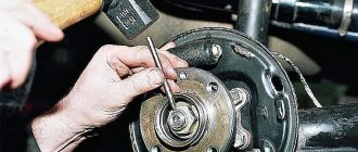
The angle grinder spindle lock (locking button) is necessary to hold it stationary when tightening the clamping nut. If it starts to sink, you need to remove the button, remove the rod and spring, and then clean the inside and visually check the condition of the rod, seal and spring. Repairing the retainer usually involves replacing one of these components (see video).
Checking the disk mounting flange
The usual support flange of an angle grinder is a simple device in the form of a disk, against which a cutting wheel is pressed. Its surface should be smooth, without potholes or burrs. It cannot be repaired, and when worn out it is simply replaced with a new one.
Checking the rotor bearings
The bearing of the drive shaft of the angle grinder, which is the rotor shaft of the electric motor, can be inspected and replaced without completely disassembling the gearbox. To do this, it is enough to disconnect the gearbox and drive housing (see figure above). If the decision is made to repair and replace the bearing, then you will have to completely remove the electric motor rotor, remove the drive gear (see photo below), and then remove the old one and install a new bearing.
How to disassemble the gearbox
When repairing the mechanical part of an angle grinder, first of all, it is necessary to separate the gearbox from the drive by unscrewing the four bolts and disengaging the drive and driven gears. To inspect it internally and repair its components, you need to remove the lower part of the gearbox, which is also bolted to the main body. Next, the gearbox is disassembled into individual parts, sequentially separating the bearings, gear and flange from the shaft.
How to remove gears
The drive gear of the grinder gearbox is usually attached to the shaft by tension and pressed with a nut, and the driven gear is fixed with a key and a split washer. The video below shows the repair procedure with disassembling the gearbox, removing the upper bearing and replacing the driven gear. The video is in English, but everything is very clear, so you can watch without sound.
Prevention of angle grinders
Prevention of an angle grinder includes compliance with passport requirements during its operation, periodic maintenance and scheduled repairs. First of all, it is necessary to strictly observe the ratio of work cycles and breaks recommended by the manufacturer. It is also necessary to periodically clean the internal space of the angle grinder body from dust, change the brushes in a timely manner and lubricate the gearbox. If persistent vibrations and uncharacteristic sounds occur during operation of the angle grinder, you should immediately carry out an internal inspection of the mechanical part and carry out the necessary repairs.
Unlike a regular angle grinder, the quick-release nut is a rather expensive device. How long can it last and is it possible to repair it if it fails? If anyone knows the answer to this question, please share the information in the comments.
The grinder is used to perform many tasks on the farm. Regular use may damage the device. The most frequently broken element is the anchor. It is subject to a high thermal load, as well as mechanical and electromagnetic influences. As a result, many craftsmen have to think about repairing this part.
Electrical equipment for angle grinders
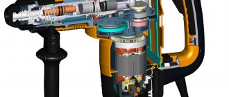
Over several decades, the external parameters of the angle grinder have remained almost unchanged, with the exception of improved models that use a battery as a battery. The basis of the tool is a housing with a built-in asynchronous motor and gearbox, and a handle with a protective housing is screwed on.
The power tool can be used with cutting and sanding discs, and there are also discs with sanding pads for sanding. Like all tools, a sander can fail to work, but most often it’s not that difficult to fix the problem. This may require disassembling the case and minor repairs of parts. However, it is necessary to understand the structure of the angle grinder, the circuit of which contains the following elements:
- Collector;
- Anchor;
- Brushes;
- Gearbox;
- Stator;
- Handle holder;
- Plug and power cord.
The performance of all elements is very important for the normal functioning of the entire system. If any part fails, the grinder becomes a useless tool. In order for the grinder disc to rotate, the armature must rotate and drive the gearbox, and the faster the armature rotates, the greater the rotation speed of the disc. The collector is a unique part in the form of a platform to which contacts of power and control electrical components lead. The commutator receives voltage from the brushes, and in a further process, electrical energy is converted into mechanical energy.
Anchor device
The armature of an angle grinder consists of a winding that conducts current and a magnetic circuit. The magnetic circuit contains a shaft that performs torsion. The structure of the magnetic wire is formed by plates and grooves, which are isolated from each other by coating with varnish. A specific sequence for laying the conductors of the armature winding in the grooves has been developed. The conductors form a coil. Its ends are tied together with lamellas. The layout of the beginning of the starting turn and the end of the last is drawn up in such a way that they are closed onto one lamella.
When the angle grinder motor constantly overheats, the armature melts. As a result of high temperature, the contacts of the wires that connect the primary winding to the collector may fall off. All this leads to the fact that no current is supplied.
Read also: How to check the zero position of a caliper
Armature fault
There are criteria on the basis of which we can conclude that the anchor requires repair:
- the number of sparks emanating from the brushes on the engine commutator increases;
- vibration appears at low speed;
- the working shaft begins to move in different positions.
The presence of these signs indicates a broken anchor. Subsequent use may be dangerous.
The following damage to the anchor is known:
- breakage of electrical conductors;
- short circuit between turns;
- insulation failure, which leads to a short circuit of the winding to the metal surface of the rotor;
- soldering the ends of the collector;
- Uneven commutator wear.
As a result of these malfunctions, the engine gradually stops working. To find out the reason for the failure of the angle grinder, diagnostics should be carried out. It can be carried out visually or using appropriate instruments.
Do-it-yourself armature manifold groove
Correct operation of the Makita 2450 rotary hammer with a commutator motor is accompanied by slight sparking of the brushes in the commutator area. A properly functioning electric motor has a uniform spark with a short tail.
By changing the sparking pattern, you can determine the nature and location of the malfunction in the Makita 2450, 2470 hammer drill.
The reasons for the increase in sparking in the electric motor commutator may be faulty brushes and their wear, short circuit or armature breakage, malfunction of the stator windings of the electric motor, breakage or improper fastening of brush holders.
Significant sparking in the commutator area leads to the appearance of grooves on the commutator, burning of the plates, and uneven abrasion of the brushes.
The occurrence of the listed defects causes rapid wear and wear of the lamellas of the collector itself.
Roughness is higher than normal
Since a hammer drill is a powerful tool, small sparks are allowed without load; with significant effort on the tool, single sparks may run in a circle. In case of strong sparking, it is necessary to find out the reason for the strong sparking.
The most common fault on the commutator is the increasing roughness of the lamellas with increasing sparking of the brushes.
An increase in the surface roughness of the Makita 2450 rotary hammer commutator occurs not only due to increased sparking. Copper oxide forms on the copper plates of the commutator; its hardness exceeds the hardness of the carbon brushes. The amount of roughness is affected by uneven wear of brushes and carbon deposits from sparking.
Scratches are formed not only due to uneven wear of the brushes and different structure of the material, but also due to the entry of solid particles from the air into the working area.
Improper storage of a Makita rotary hammer can lead to the appearance of oxide on the copper plates of the collector due to high humidity or significant temperature changes during operation.
To eliminate defects on the surface of the collector, it must be sanded.
How to properly sand the surface of the commutator
Before you begin to modify the manifold of the Makita 2470 rotary hammer, you must balance the rotor.
Option for measuring the runout of the commutator relative to the rotor
At home, grinding the manifold of a Makita 2450 or 2470 rotary hammer is best done with sandpaper attached to a wooden block already on a balanced rotor.
The end of the rotor shaft is secured in the drill chuck through soft copper or aluminum foil. A drill with a rotor is securely fastened in a vice or homemade device.
While rotating the rotor, try to center it in the drill chuck.
Installing the rotor into the chuck
How to center the rotor in a drill before grinding
The rotor is centered in the drill chuck to ensure minimal runout of the radial surface of the commutator relative to the rotor shaft.
First check the runout of the chuck jaws. Secure the drill in a vice, install a drill of the largest diameter in the chuck.
While rotating the drill, bring a pencil to the rotating side surface of the drill, resting it on a simple stop. With minimal runout, the pencil will draw a solid line on the surface of the drill. If the runout is significant, change the chuck in the drill or select a drill with less chuck runout.
Now, instead of a drill, clamp the rotor shaft and in the same way determine the runout locations of the rotor or commutator.
Commutator grinding process
The process of grinding the collector must begin with the selection of sanding material. It is recommended to use sanding paper or a file to sand the commutator.
Choose several sizes of sanding paper, starting from #100 and above.
Now start sanding. Applying a wooden block with sandpaper attached to the commutator, rotate the drill and, without pressing the block too hard to the surface of the commutator, grind.
Grinding the commutator in a drill
It is recommended to use the grinding operation on already operating rotors with minor wear on the commutator.
Proper brush sparking
If you have replaced the commutator on the rotor of the Makita 2470 rotary hammer, then after installing it on the shaft, the commutator must be machined. This operation is performed to eliminate radial runout of the surface of the lamellas of the new collector relative to the armature shaft.
It is best to grind the manifold on a lathe using mandrels. But this operation can also be performed at home. True, you can’t do without additional devices. will help you understand the manifold groove.
As a rule, brush holders on hammer drills are mounted opposite each other. Prolonged operation of the brushes leads to the formation of grooves on the collector, creating waviness on the surface. Such wear can only be eliminated on a lathe by turning the commutator.
To reduce the formation of grooves on the commutator, you should try to arrange the brush holders in a checkerboard pattern.
How to clean the slots of a rotary hammer manifold
But the grooves between the lamellas must be cleaned, since micanite, the material of the gaskets between the lamellas, is harder than copper lamellas and wears out less. Over time, micanite spacers wear less, and their height exceeds the height of copper lamellas.
To equalize the heights, the grooves between the lamellas are milled, or, in simple terms, resurfaced.
Do-it-yourself milling is best done with a piece of metal saw sharpened to the width of the collector grooves.
Milling grooves by hand
A metal ruler is applied parallel to the edge of the groove, the saw is pressed against its edge and pulled out with gentle pressure. The groove is milled to the height of the copper lamella.
Milling of grooves ends by removing the remaining material using a hair brush and chamfering using a scraper made from a needle file. It is better to sand with felt.
Any milling should be completed by grinding and blowing air.
The level of collector output is also affected by the condition of the bearings. Worn bearings lead to increased commutator runout, which in turn leads to accelerated wear of the carbon brushes. To eliminate collector runout, it is recommended to replace suspicious bearings with new ones.
How to check the condition of the brushes
When installing new carbon brushes, it is recommended to grind them in for a better fit to the commutator surface.
It is best to adjust carbon brushes using a homemade grinder. The lap is a shaft on which sandpaper is attached.
The easiest way is to make the shaft from wood with a diameter equal to the diameter of the commutator, turning the workpiece on a lathe. A metal rod is inserted tightly along the axis inside the shaft.
The device is attached to the chuck of an electric drill, the drill is turned on, and the brushes are brought to a rotating emery wheel.
The adjustment should be carried out carefully, periodically applying the brushes to the rotor commutator to check their clearance.
Having ground the brushes to the commutator, it is recommended to check the correct fastening of the brush holders before installation.
When factory installed, the brush holders are set to neutral, which minimizes sparking on the commutator.
If there are no factory marks, then the installation of the brush holders is adjusted by moving the brush holder in the direction opposite to the rotation of the rotor until a minimum spark is formed.
The brushes should not dangle in the brush holder, but should be pressed tightly against the commutator lamellas. The pressing force is regulated by springs in the brush holder.
Sparking faulty collector
An increase in sparking on the rotor commutator may appear due to a short circuit of the armature, a break in the armature coils, or a short circuit of the windings to the armature body. All these faults can be eliminated only with a major overhaul of the rotor.
How to check the anchor on an angle grinder?
Visual inspection rules
Standard diagnostics involve visual analysis of the device. It is necessary to analyze the integrity of the wire and the current supply to the motor commutator. If the power supply is normal, you should inspect the grinder from the inside. Disassembling the device will not be difficult. When disassembling, it is best to photograph the location of the main modules of the device. After disassembly, visually check the anchor for the following properties:
- the anchor must move freely;
- absence of black spots and odor, which may indicate melting of the winding, the insulating varnish of which leaves traces;
- absence of crumpled turns and solder residues, which leads to a short circuit;
- there should be no burnout on the lamella contacts, otherwise you should check the connection between the lamella cockerel and the winding bar;
- no worn or burnt out records;
- the space between the lamellas should not contain graphite residues from brushes.
If a visual inspection does not reveal any deficiencies, then it is necessary to carry out an instrument check. The anchor on an angle grinder can be checked either using a tester or using a regular light bulb.
Inspection using a tester
The multimeter is set to the ohmmeter position. The resistance is set to 200 ohms. The probes are connected to the lamellas located next to each other. If the value on the device is less than 1 ohm, then there is a short circuit. If the value is greater than the average, there may be a break in the turns. If the resistance value is high or there is no value (in the case of using a digital device), a break can also be judged.
There are situations when a break is not detected. Then a test for mass is done. At maximum resistance, one of the probes is placed on the shaft, and the other moves along the plates. If the value is zero, then there is no damage. Then the rotor is checked in the same way with a multimeter. In this case, the probe moves along the lamellas. If it is impossible to check with a tester, a light bulb is used.
Control using a light bulb
In the absence of a device at hand, many are interested in the question of how to check the angle grinder for possible anchor damage. The power supply wire is broken and a light bulb is placed where one wire breaks. Then the shaft rotates. By changing the brightness of the light bulb, you can judge the short circuit between the turns. In the absence of combustion, the following conclusions are possible:
- the location of the brushes does not correspond to the working position due to the activation of the support spring;
- rupture of the supply circuit;
- short circuit or break in the stator winding.
You can ring with an indicator of short-circuited turns and an armature tester. This can be done by an experienced person.
Rewinding the armature
Anchors for angle grinders can be rewound at home. To do this, you need to have certain skills when working with a soldering iron. To rewind the armature with your own hands, you will need:
- a wire with a copper core that matches the previous conductor;
- dielectric paper to insulate the winding;
- varnish for filling coils;
- soldering iron
Before starting to wind the armature, it is important to count the number of turns in the old winding and do the same number on the new coil.
- removing previous windings - try not to damage the surface of the housing. If damage occurs, sand with sandpaper or a file;
- inspection of the collector - the resistance value of the lamella contacts in comparison with the shell should not exceed 0.25 Mohm;
- cleaning the collector from old wires - developing grooves for inserting the ends of new wires;
- placement of sleeves - they are made of non-conducting material, for example, electrical cardboard. Their size is 0.3 mm;
- rewinding the coils - the end of the new wire is attached to the end of the lamella. Rewind in a counterclockwise direction. Secure the wires near the collector with cotton thread;
- control for the absence of short circuits - measure the resistance with a tester;
- applying varnish or epoxy to secure the winding - dry it in the oven or use products that dry quickly.
If it is not possible to perform such actions, then you can replace the angle grinder’s anchor.
Anchor change
Replacing the armature on an angle grinder is carried out simultaneously with replacing the support bearings and the motor cooling impeller. To perform this you will need the following equipment:
- a new anchor for an angle grinder, suitable specifically for your device;
- screwdriver and wrench;
- a brush with soft bristles and a cloth for wiping elements.
Disassembly steps:
- removing brushes;
- unscrewing the gearbox;
- removing the gearbox cover;
- removing the ring that secures the small gear to the armature;
- removing the armature together with the gear and bearing;
- removing the bearing using a special removable device;
- removing the gear and fastening disk;
- wiping the main elements with a napkin.
Installing a new part for the grinding machine is carried out in the reverse order:
- installing the securing disk on the shaft;
- bearing pressing;
- installing a small gear and securing it with a retaining ring;
- placing the anchor in the gearbox with connecting holes;
- securing the gearbox in the angle grinder body;
- installation of brushes;
- device check.
Thus, repairing an anchor with your own hands can be done quickly and easily. But in order to prevent such cases, you need to use the device carefully and not subject it to prolonged high loads. Keeping the tool in a dry place and taking the necessary care will extend its service life.
Repairing an angle grinder with your own hands: the principle and design of the device
Repairing an angle grinder is not an easy task; you need to know all the intricacies and reasons why the device may fail. For example, repairing an asynchronous motor or a sparking collector is not always within the power of an ordinary person. And here you will have to turn to the master. In order to understand what the grinder consists of, you need to know how this technique works. Using electricity, the motor operates, which transmits rotation to the shaft thanks to the gear. A cutting or grinding wheel is installed at the end of the shaft.
Read also: Drilling square holes in wood
The quality of work of an angle grinder depends on the number of revolutions per minute. The professional tool is capable of reaching a speed of 1000 rpm.
The first thing to do in the event of a breakdown is to disassemble the device and clean it; in most cases, the angle grinder starts working.
If this does not happen, you need to understand where exactly the breakdown occurred. The composition of the grinder may differ depending on the model, but their main parts are the same.
When disassembling, we can see 4 components:
- The body, which consists of 2 parts;
- Engine;
- Gearbox;
- Electrical component.
The engine causes the gear to move, which in turn drives the cutting element.
Oddly enough, in most cases, the breakdown of angle grinders occurs due to the accumulation of dust and, as a result, the power button comes off. Therefore, first you need to determine the integrity of the electric drill, its blades and battery. All this is not so difficult, it is enough to know how the device works. If you have ever studied the structure of a vacuum cleaner or washing machine, then this will seem like a trifle to you, but a special video can help.
Verification methods
Each rotor malfunction is identified by an appropriate test method.
Visual inspection
The test method with which to begin diagnostics. Check the armature commutator for mechanical damage. There should be no scratches, nicks or chips. Inspect the slats for burnout. If one of them is darker or swollen, there is a short circuit between the plate and the winding bus.
12 volt light bulb
Connect two wires to the contacts of the light bulb. Make a gap in one of them. Connect the wires to the power source, place the edges of the “broken” wire on the lamellas so that they do not touch each other. Rotate the anchor. If there are no breakdowns in the winding, the light will light continuously.
Multimeter
Switch this device to resistance measurement mode. Place one of the probes (polarity does not matter) on one of the plates. Apply the other probe one by one to the remaining lamellas. A sound signal, depending on the model of the multimeter, will notify that there is a breakdown between the “winding paths”.
Tester
Indicator of short-circuited turns. Used for diagnostics of closed type anchors. This type of rotor is characterized by the lack of access to the junction of the winding with the lamellas. The tester has two LEDs - red and green. By rotating the armature connected to the tester, you can determine the presence of a breakdown in the winding by the red LED that lights up.
Anchor on an angle grinder: how to check the armature of an electric motor at home
If you are absolutely sure that the anchor is broken, then you will need to get the electric motor.
Disassembling the motor should be carried out as carefully as possible. Disconnect all brushes and terminals from power.
Do not forget that before changing the winding, no matter which power tool Bosch, Sparky, Makita, Interskol, you need to manually determine the reasons for the breakdown of the grinding machine. To do this, a winding and gear diagram, as well as a special indicator, will help you. We take out the rotor, and with it the support bearings and the cooling impeller. All this represents a single whole object. If you notice that most of the wiring is damaged and the balance is off, then it is better to replace this component completely. The fact that the balance is disturbed can be indicated by the appearance of hum and vibration in the mechanism.
If the balance of the anchor is not disturbed, and the problem is only in winding, then the anchor must be restored. The work will involve rewinding the coil yourself, everything must be done carefully with patience and accuracy. If the balancing of the angle machine works intermittently, then first you need to check it with a tester. If the groove shows different data, you will not be able to repair the electric motor yourself. But a replacement will help restore it.
In order to replace the rewind in the armature you will need:
- New wires for winding should be copper wires, the diameter of which will correspond to the previous wires;
- Dielectric paper for winding insulation;
- Varnish to fill the coils;
- Soldering iron with solder and rosin.
Before rewinding, you need to count the turns of the wire and apply the same number in the new winding.
Step-by-step instructions: how to rewind an electric motor at home
If the problem does not concern the starter or gear, but you find a problem in the winding, then here you will have to purchase copper and enlist the help of a commutator puller. To begin with, you need to test the circuits with a tester; a multimeter will help you check, and in order to check the functionality of the device, use a short-acting transformer. This way you can choose the necessary actions and tools to subdue the angle grinder.
The process itself consists of the following steps:
- Removing the old winding. It must be removed carefully so as not to damage the metal body of the anchor itself. If you find scratches or burrs, they need to be smoothed out using sandpaper or a soldering iron. Sometimes a torch is used to ensure that the body is completely cleaned.
- Preparing to connect new wires. There is no need to remove the collector itself. You will need to inspect the lamella and measure the resistance of the existing contacts in relation to the housing with a multimeter. The indicator should be approximately 0.25 Mohm.
- Removing old wires. Residues must be carefully removed and grooves cut in the contacts. They will be needed later to insert the coil wires.
- Installation of sleeves. The sleeves are made from electrical cardboard, a material whose thickness is no more than 3 mm. The required amount is cut and inserted into the grooves of the armature.
- Rewind. The end of the wiring must be soldered to the end of the lamella and wound in a circle counterclockwise. The same action is repeated for all tubs.
- Quality checking. After all the windings are made, use a multimeter to check for shorts or breaks.
- Final treatments. The finished coil is treated with epoxy resin or varnish. At home, the finished work is dried in the oven. You can use a varnish that dries faster.
The work may seem difficult. We hasten to assure you that no, but you will have to spend a lot of time and effort on this.
How to check the stator for interturn short circuit with a multimeter
The anchor is the part on which a large amount of dirt most often accumulates. If the grinder has any malfunctions, you can identify them by yourself using a multimeter or, in other words, an ammeter.
The test begins with finding the faulty component. If your device is completely out of order, this may be evidence of scattered brushes or a damaged dielectric layer that is located between the plates. If you observe sparking inside, this means that the current collectors in the angle grinder are damaged.
Regardless of what result you get during the examination, you need to check the resistance. It should be the same for each measurement.
If the indicators show a deviation, this indicates a violation of the connection of the coils and a poor fit of the brushes.
Pay attention to the brushes, their wear should be the same, and if there are scratches, they must be replaced with new ones. If you do not find any malfunctions, then you need to measure the resistance at the lamella and coil.
How to change
Regardless of the models of grinders, the method of replacing bearings is not much different from each other. Adjustments to repair technology are related to the design features that each brand has.
Bosch
The following video describes replacing the gearbox bearings on one of the Bosch models, which has a lot of play on the spindle. Here, the main executive body that creates the pressing/pressing forces is a conventional bench vise. The use of various extensions in the form of correspondingly sized pipes and other similar parts allows you to transfer forces to the desired place in the structure using the movement of the vice jaws. Some operations are performed using extensions and light hammer blows.
A design feature is a flange filled with plastic. To press out/press in the flange bearing, the author used a knife and a torch to remove the plastic that interfered with this process. Perhaps, if you have the skills of a turner, you can simply cut this material on a machine.
Makita
One of the Makita models describes the process of replacing bearings without the use of special tools, using any available means. Wooden blocks made of hardwood are used as base surfaces, which bear the load when performing various technological operations using force.
As equipment, metal sheets of suitable thickness and socket heads are used (pipes of suitable size can be used) when knocking out bearings. The centering holes of the shaft serve as the base for a pointed rod (in the video this is a modified old screwdriver), with the help of which the shaft itself is released. The only industrial production tool is a circlip puller, although even without it you can figure out how to remove them using improvised means.
Interskol
Some designs of bearing units are made without the use of interference fits. So, for example, in the following video, the ball bearing of the gear housing cover of the Interskol model is assembled into a supporting structure using a washer secured with threaded connections. For a better fit to the plane of the body, the surface of the washer is coated with an adhesive composition.
Hitachi
Some designs of bearing assemblies at first glance exclude the possibility of replacing the bearing itself included in such an assembly. However, the author of the following video found a way to do this in one of the Hitachi models and thereby save a decent amount of money using the proposed method.
To secure the bearing assembly in the drill, a wood bit was used, into the inner surface of which one of its outer diameters fits tightly. With the drill running, a sharp object is used to remove plastic material up to the size of the outer ring of the bearing. Thus, nothing prevents you from removing the bearing using a hammer and an extension.
Next, when assembling a new bearing, a ring is inserted instead of the ground plastic (in the video it is most likely made of caprolon or other similar material). Since the ring in the video has a wall thickness that does not allow the gear to be assembled according to the technical requirements, its internal diameter is modified to the required size using a chisel.
Sparky
After analyzing the condition of the components and parts, it turned out that the cause of the malfunction of the angle grinder was the front rotor bearing. It was easily replaced with a new one, which was inserted into the gearbox housing without interference and secured with a washer using threaded screws. The lifespan of the Sparky angle grinder from the video is 15 years, so other defects cannot be ruled out and the author correctly draws the conclusion about purchasing a new angle grinder.