It's been about a year and a half since I started doing electronics repairs regularly. As it turned out, this matter is no less interesting than the design of electronic structures. Little by little people appeared who wanted, some from time to time and some regularly, to collaborate with me as a master. Due to the fact that the profitability of most of the repairs carried out does not allow renting premises, otherwise rent eats up most of the profit, I work mainly at home or go with tools to familiar individual entrepreneurs who buy consumer electronics and have a workshop.
In parallel with a friend, we buy equipment on the local forum and Avito, repair it and the friend sells it, both in shares of the sale. But that's not the point. Today I decided to share with readers a diagram of a simple, but very useful for any electronics repairman, ESR meter, which allows you to correctly measure this parameter, in most cases, without soldering the electrolytic capacitors. ESR, also known as ESR (Equivalent Series Resistance) is a capacitor parameter that greatly influences its performance when operating in high-frequency circuits. What kind of devices are these?
These are absolutely any circuits using stabilizers, DC-DC power converters, switching power supplies for any equipment, from computers to mobile chargers.
Swollen capacitor
Without this device, a significant part of the repairs I performed either could not have been performed at all, or was still performed, but with great inconvenience in the form of constant soldering and soldering back electrolytic capacitors of small value, in order to measure the equivalent series resistance using a transistor tester. My device allows you to measure this parameter without desoldering the part, simply by touching the terminals of the capacitor with tweezers.
These capacitors with a nominal value of 0.33-22 uF, as is known, very rarely have notches in the upper part of the case, along which capacitors of a higher nominal value swell and open like a rose, for example, the familiar capacitors on motherboards and power supplies. The fact is that a capacitor that does not have these notches to release the excess pressure generated is visually, without measuring with a device, even for an experienced electronics engineer, in no way distinguishable from a fully working one.
Computer power supply
Of course, if a home craftsman needs a one-time repair, for example, an ATX computer power supply, there is no point in assembling this device; it is easier to immediately replace all the small capacitors with new ones, but if you repair at least five power supplies every six months, this device is already desirable for you assembly. What alternatives are there to assembling this meter? A purchased device that costs about 2000 rubles, ESR micro.
ESR micro – photo
Of the differences and advantages of a purchased device, I can only name that its readings are displayed immediately in milliOhms, while my device needs to be converted from milliVolts to milliOhms. Which, however, does not cause any difficulties, it is enough to calibrate the device using the values of low-resistance precision resistors and create a table for yourself. After working with the device for a couple of months, visually, without any tables, just by looking at the display of the multimeter you can already see the normal value of the ESR of the capacitor - on the verge or replacement is already necessary. The diagram of my device, by the way, was once taken from Radio magazine.
How to test a capacitor with a multimeter
Essentially, repairing any electronic equipment comes down to finding and replacing faulty parts. And you might be surprised at how often seemingly simple components like capacitors fail.
While delicate diodes, sensitive transistors and complex microcircuits remain safe and sound. Typical capacitor faults:
- Short circuit between the plates. As a rule, this is a consequence of mechanical damage, overheating or exceeding the operating voltage (breakdown). The simplest case, because easily detected by any multimeter in dial mode;
- internal break with complete loss of capacity (that’s why you can’t short-circuit with screwdrivers). In the case of high-capacity capacitors, this defect is quite easily diagnosed. Detecting a break in small conductors (less than 500 pF) is a rather labor-intensive task and can only be done with the help of special devices. devices;
- partial loss of capacity. For electrolytic capacitors, loss of capacitance over the years is almost inevitable, but this does not always lead to failure of the device (but may degrade its performance). Ceramic, film and others with a solid dielectric are usually more stable, but may lose capacity as a result of mechanical damage;
- leakage resistance is too low (the capacitor “does not hold” a charge). This is mainly characteristic of electrolytic capacitors. Although tantalum ones are very good in this regard;
- Equivalent series resistance (ESR) is too high. The problem mostly concerns “electrolytes” and only appears when working with high-frequency or pulsed currents.
There are many ways to test a capacitor with a multimeter for functionality.
Useful tips
Useful tips from experts:
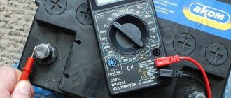
- The voltage in a charged storage device with a large capacity can be checked by closing the contacts using a screwdriver with an insulated handle - a powerful spark should flash through.
- Before starting research, it is advisable to install a fresh battery in the multimeter or other device you are using.
- It is better to desolder or disconnect the part being tested from the circuit.
- You should not touch the contacts with your hands during the examination, as they may be under dangerous voltage or the device readings will be distorted.
Checking the capacitor with a multimeter
First, let's figure out what kind of device this is, what it consists of, and what types of capacitors exist. A capacitor is a device that is capable of storing electrical charge. Inside, it consists of two metal plates parallel to each other. A dielectric (gasket) is located between the plates. The larger the plates, the correspondingly more charge they can accumulate.
There are two types of capacitors:
- 1) polar;
- 2) non-polar.
As you can guess from the name, polar ones have polarity (plus and minus) and are connected to electronic circuits with strict observance of polarity: plus to plus, minus to minus. Otherwise, the capacitor may fail. All polar capacitors are electrolytic. They come with both solid and liquid electrolytes. The capacitance ranges from 0.1 ÷ 100000 µF. Non-polar capacitors do not matter how they are connected or soldered into the circuit, they do not have a plus or minus. In non-polar conductors, the dielectric material is paper, ceramics, mica, and glass.
It will be interesting➡ How to make a microphone from a phone with your own hands
Their capacitance is not very large and ranges from a few pF (picofarads) to a few microfarads (microfarads). Friends, some of you may be wondering why this unnecessary information? What is the difference between polar and non-polar? All this affects the measurement technique. And before you check the capacitor with a multimeter, you need to understand what type of device is in front of us.
How to test a capacitor using instruments
First of all, an external inspection of the capacitor is performed for cracks and swelling. Often the cause of a malfunction is internal damage to the electrolytes, which in turn leads to an increase in pressure inside the housing, and as a result, swelling of the shell. If the capacitor appears to be intact, then without special instruments it is difficult to say whether it is functional or not. Therefore, in this case, the capacitor is checked with a multimeter. This simple device will allow us to determine the capacitance of the capacitor and the presence of breaks inside.
Various capacitors.
Before you start checking, you need to decide what type of capacitor is in front of you: polar or non-polar. Remember, I wrote above that this will be important when measuring. So, when checking polar capacitors, you need to observe the polarity and connect the probes to them accordingly: the positive one to the “+” leg, and the negative one to the “-” leg. When checking non-polar “conders”, the polarity in the connection does not need to be observed, however, there is one feature that you need to pay attention to. To check the integrity of the condenser, the multimeter switch must be set to 2 MOhm.
If it is less, the display will display “1” (one), you may falsely think that the capacitor is faulty. We install the multimeter switch in the resistance measurement sector (ohmmeter mode). The resistance mode will let us know whether there is a break or short circuit inside the condenser. To do this, set the switch to the 2 MOhm mark and touch the leads of the capacitor with the probes. As soon as the probes are connected, you can see a rapidly increasing resistance on the display.
Why is this happening
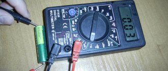
Why do you see “floating resistance values” on the display? The thing is that when the probes touch the terminals, a constant voltage is applied to the capacitor (device battery) - it begins to charge. The longer we hold the probes, the more the capacitor is charged, and the resistance gradually increases. The charging speed directly depends on the capacity. After a while, the capacitor will charge and its resistance will be equal to “infinity”, and on the multimeter display we will see “1”. This is an indicator that the capacitor is working.
Not everything can be conveyed in photographs, but for a 5.6 uF sample the resistance starts at 200 kOhm and gradually increases until it exceeds the 2 MOhm mark. The whole process lasts approximately 10 seconds. With the second capacitor with a nominal value of 3.3 μF, everything happens in a similar way. It begins to charge, the resistance increases, as soon as the readings exceed the 2 MOhm mark, you can see “1” on the display, which corresponds to “infinity”. The process takes less time, about 5 seconds.
Related material: How to check a varistor with a multimeter.
Replacement
Removing the capacitor of the VAZ 2110 generator and checking it is carried out in the following order:
- Disconnect the battery (just disconnect the negative terminal);
- Disconnect the excitation wire (wire block at terminal “D”);
- Using the “10” key, unscrew the “B+” output wire;
- Remove the generator belt;
- Unscrew the fixing nut, the adjusting bolt and remove the belt tensioner bar;
- We take out the lower fastening bolt, first use a key “13” and unscrew its nut;
- Carefully pull out the generator itself (see photo).
Generator removal process
Next, we begin to get directly to the “culprit” of the repair:
- We remove the plastic protective casing by pressing the three latches on its body:
- We unscrew the two screws securing the brush holder and carefully, trying not to damage the brushes, pull out the assembly itself, simultaneously disconnecting the wire block from it;
Unscrew the nut securing the bolt and remove the tip of the condenser contact wire along with the spring and spacer washer;
Capacitor Contact Wire
Unscrew the fastening screw and remove the “victim”.
Removing the capacitor of the VAZ 2110 generator, video
Measuring capacitance of a capacitor with a multimeter and special devices
Some multimeters have a capacitance measurement feature. Take these common models: M890D, AM-1083, DT9205A, UT139C, etc. There are also digital capacitance meters on sale, for example, XC6013L or A6013L. Using any of these devices, you can not only find out the exact capacitance of the capacitor, but also make sure that there is no short circuit between the plates or an internal break in one of the terminals.
It will be interesting➡ How to make a flashing LED?
Some manufacturers even claim that their multimeters can test the capacitance of a capacitor without desoldering it from the board. Which, of course, contradicts common sense.
Unfortunately, testing a capacitor with a multimeter will not help determine the most important parameters such as leakage current and equivalent series resistance (ESR). They can only be measured using specialized testers. For example, using a very inexpensive LC meter.
Measuring capacitance of a capacitor with a multimeter and special devices.
Short circuit test
There are three ways to do this.
Method No. 1: determining short circuit in dialing mode
How to test capacitors with a multimeter? You need to turn the multimeter into continuity or resistance measurement mode and attach the probes to the terminals of the capacitor. Depending on the capacitance, the multimeter will either immediately show infinite resistance, or after some time (from a few seconds to tens of seconds). If the device constantly beeps in dial-up mode (or shows very low resistance in resistance measurement mode), then the capacitor can be safely thrown out.
Interesting material for familiarization: what are variastors.
Method No. 2: determining a capacitor short circuit using an LED and a battery
If you don’t have a multimeter (and you don’t even have an old Soviet “tseshka”), then you can try connecting an LED or light bulb to the battery through the capacitor being tested. Because A working capacitor has a very high resistance to direct current, the light bulb should not light up.
Although, if the capacitor capacity is large enough, the light bulb may flash for a short time (until the capacitor is charged). If the LED is constantly on, the capacitor is 100% faulty. If, when checking a capacitor, the effect of a gradual increase in resistance up to infinity is observed (or the LED flashes and goes out for a while), then the capacitor definitely has some kind of capacitance.
Therefore, there is no need to check for a break.
Method No. 3: checking the capacitor with a 220V light bulb
Suitable for high-voltage non-polar capacitors (for example, starting capacitors from washing machines, pumps, various machines, etc.). All you need to do is simply connect a low power incandescent lamp (25-40 W) through a capacitor.
Defining parameters
It’s very easy to check the element’s functionality yourself. Modern multimeters and testers have a corresponding function for this. The main parameter during testing will be the compliance of the declared and actual capacity, as well as the throughput of the radio component. The test can be carried out both on the board itself and by removing the part from the printed circuit board.
Capacity check
Often capacitors, especially old ones, have unclear capacitance markings on their housings. In order to find out the capacity of the working device, you need to use a multimeter that has a capacity measurement function. Modern multimeters have a measuring range from 20 nF to 200 mF. To determine the capacitance of an unmarked capacitor, you will have to test it in 5 modes: 20 nF, 200 nF, 2 mF, 20 mF, 200 mF. You will also have to take polarity into account if the element is polar. Before measurement, it is necessary to remove the capacitor from the circuit.
- The device switches to capacity test mode. Be sure to switch the probes to the cX socket.
- The element under test must be discharged before testing. This is done by shorting both ends.
- Both probes are connected to the terminals.
The resulting value is the nominal capacity.
Polarity Determination
To determine the polarity, you can visually inspect the housing. Definition of "+":
- Soviet capacitors had a “+” sign on the case on the side of one of the legs.
- Modern radio components are also marked on the housing with a “+” sign.
- SMD capacitors have a “+” sign on one side or are marked with a colored stripe.
The minus is also determined visually:
Modern capacitors have different body colors. On black or blue cases, the minus is indicated as a silver stripe or a blue arrow. SMD elements are marked with a blue or black stripe. Often on them the “+” side has a convexity, and the minus is simply flat at the end. New capacitors, even before installation, have a positive leg, which is much longer than the negative leg.
Checking for internal continuity
A break is a common defect in a capacitor in which one of its electrodes loses electrical connection with the plate and actually turns into a short conductor not connected to anything (hanging in the air). Most often, a break occurs due to the operating voltage of the capacitor being exceeded. This is caused not only by electrolytic capacitors, but also by special noise-suppressing capacitors of the Y type (they, by the way, are specially designed to go into isolation and not into a short circuit).
A capacitor with an internal break is no different in appearance from a working one, except in cases where the leg is physically torn off from the body. Of course, if one of the leads is torn off from the capacitor plate, the capacitance of such a capacitor becomes zero. Therefore, the essence of checking for a break is to catch at least the slightest sign of the presence of capacitance in the capacitor being tested.
Table of capacitor reliability characteristics.
Method No. 1: eliminating a break through the sound signal in dialing mode
Turn the multimeter into dial mode, touch the leads of the capacitor with the probes, and at this moment the multimeter should emit a short squeak. Sometimes the sound is so short (depending on the capacitor capacity) that it sounds more like a click and you have to try really hard to hear it. A small life hack: to increase the duration of the sound signal when testing very small capacitors, you need to first charge them with negative voltage by applying the multimeter probes in the reverse order.
Then, during the subsequent continuity test, the multimeter will first have to recharge the capacitor from some negative voltage to zero, and only then from zero until the tweeter turns off. All this will take much more time, which means the signal will sound longer and will be easier to hear. From my practice, I can say that using the trick described above, I was able to catch the response of a multimeter to a capacitor with a capacity of only 0.1 μF (or 100 nF)!
It will be interesting➡ How to test a transformer using a multimeter
Method No. 2: increasing DC resistance as a sign of no break
If the previous method did not help and it is not at all clear how to check the capacitor with a tester, then here is a more sensitive testing method. It is necessary to switch the multimeter to resistance measurement mode. Select the maximum available measurement limit (20 or better 200 MOhm). Apply the probes to the capacitor terminals and observe the multimeter readings.
As the capacitor is charged from the multimeter's internal source, its resistance will continually increase until it exceeds the measurement range. If such an effect is observed, then there is no break. By the way, it may turn out that the increase in resistance stops at a value from a few to a couple of tens of megohms - for capacitors with liquid electrolyte (except tantalum) this is absolutely normal. For other capacitors, the leakage resistance should be at least an order of magnitude greater.
When measuring such high resistances, you must be careful not to touch both test leads with your fingers. Otherwise, skin resistance will make its own adjustments and distort all results. By measuring resistance at a limit of 200 MΩ, I was able to unambiguously determine the absence of a break in capacitors with a capacity of only 0.001 μF (or 1000 pF).
Reasons why the generator is not charging
- Brush wear
The most common reason why the generator does not charge the battery. This is wear on the brushes. The carbon contacts that transmit voltage from the regulator relay to the rotor windings are erased and the contact disappears. With this malfunction, the warning lamp on the instrument panel stops lighting up.
That is, when the ignition is turned on, if everything is working properly, the charging control icon should light up. The engine starts and the lamp goes out. This means that the generator is running and charging the battery.
In case there is no contact on the brushes. The light does not light up when the ignition is turned on. You can make sure that the reason is in the contacts.
The wire that goes to the regulator relay must be shorted to ground. Turn on the ignition. The light should light up. This means that there is no contact between the brushes and the slip rings. Or there is a break in the rotor winding.
If the charging indicator lamp does not light up when the wire is shorted to the housing. This means the LED has burned out. Which lights up the charging icon. Or a broken wire. It is necessary to ring the circuit from the regulator relay to the instrument panel.
2. Malfunction of the relay regulator
How to check whether the generator is charging the battery if the regulator relay integrated circuit fails. Two faults are observed. The generator stops charging. Because the relay regulator does not supply voltage to the rotor winding. Or, on the contrary, the generator voltage increases with increasing speed. This exceeds the permissible voltage for the vehicle's electrical system. This may cause the battery to overcharge. Which will lead to destruction of the plates and short circuit of the battery. Excessive voltage will also lead to failure of the vehicle's electrical equipment.
Checking the regulator relay
The relay regulator can be checked. Using a power supply capable of smoothly changing the voltage from 10 to 20 volts.
The relay regulator is connected according to the following diagram:
When the voltage increases above 14.2 _+ 0.3 volts, the light should go out. If the voltage decreases, the light comes on. This means that the relay regulator is working
3. Low tension of the generator drive belt.
If there is any doubt that the generator is not charging, the first thing to check is the tension of the drive belt. Because the resulting magnetic fluxes create resistance to rotor rotation. When the generator starts up. A loose belt slips on the generator pulley. The rotor stops rotating. The generator does not produce voltage
If you don't immediately pay attention to the belt tension. Generator diagnostics will not give results
In fact, the fault will have to be found on a working generator. This malfunction is classified as curious. But they fall for it very often.
These are external signs of how to check whether the generator is charging the battery. If they were not enough to determine the malfunction. Next you need to remove the generator. Disassemble it and check its elements separately.