Home » Building a house » Categories » Electrics
Alexander Korovaev 09.29.2019
1141 View
Electricity is not something to joke about, but you shouldn’t be afraid of it either. If you correctly understand the structure of electrical networks, at least at the initial level, then nothing bad will happen.
In order to use electricity safely, the average person needs to know a few easy-to-understand things, which include the concepts of phase, zero and grounding.
Many people know what a phase is, but few know what zero and ground are, what is the fundamental difference between these concepts.
What are “zero” and “ground” according to the PUE?
What we are used to calling “zero” and “ground” in the PUE is called the zero working conductor ( N ) and the zero protective conductor ( PE ). Here is how they are interpreted in the regulatory document:
1.7.17. A protective conductor (PE) in electrical installations is a conductor used to protect people and animals from electric shock. In electrical installations up to 1 kV, the protective conductor connected to the solidly grounded neutral of the generator or transformer is called the neutral protective conductor.
1.7.18.a The neutral working conductor (N) in electrical installations up to 1 kV is the conductor used to power electrical receivers, connected to a solidly grounded neutral of a generator or transformer in three-phase current networks, to a solidly grounded terminal of a single-phase current source, to a solidly grounded source point in three-wire networks direct current.
From these formulations it is clear that the protective neutral conductor is necessary to protect against electric shock. That is, electrical equipment must be grounded to it, for example, a washing machine, boiler, boiler, etc. At the same time, the working neutral conductor is necessary to power the equipment, that is, current will flow through it.
In some cases, it is allowed to use “zero” (PE) as “ground”, as specified in PUE 1.7.18.b. In this case, the wire becomes a combined conductor, which combines the functions of the zero protective and zero working conductors. It will be called PEN. However, there is one nuance that is important to know.
The fact is that according to PUE 1.7.83 “There should be no disconnecting devices or fuses in the circuit of grounding and neutral protective conductors.” That is, the neutral protective conductor (“ground”) must run continuously from the panel to the outlet or lighting fixture. If we, for example, ground the ground to zero, then the "path" is interrupted by removing the plug from the socket. And if a breakdown occurs, the body of the remaining equipment grounded to this wire will be energized.
Further in the same paragraph it is said: “In the circuit of neutral working conductors, if they simultaneously serve for grounding purposes, it is allowed to use switches that, simultaneously with disconnecting the neutral working conductors, disconnect all live wires.” It follows from this that “zero” can be used as “ground” if, when it is turned off, all live steel conductors are also turned off. It is quite difficult to do this in an apartment environment.
- Technologies
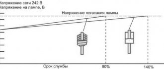
Why is the voltage in the networks 110 V in the USA, and 220 V in Russia?
How to use zero as a ground
If there is no grounding in the old apartment, then you can make it using zero for these purposes. To do this, the zero in the electrical panel of the house must be divided into “protective” and “working”. For these purposes, an additional busbar for PE conductors is installed in the electrical panel, connected by a jumper to zero.
However, there is an important rule! Thus, electrical appliances can only be connected to the protective circuit through a special contact. It is strictly forbidden to use the usual grounding contact on electrical appliances for these purposes, since a break in the zero will lead to the fact that the metal parts of the electrical appliances will be under dangerous voltage.
In this case, the best safety option would be to install an RCD - a residual current device. In the event of a current leak, the RCD will detect a dangerous potential and automatically disconnect the electrical appliance from the 220 Volt network.
The operating principle of the residual current device is based on the following:
- Roughly speaking, the RCD controls how much voltage has gone through the phase wire and how much has returned through the neutral wire;
- If there was no “return”, that is, there was a current leak, then the RCD will see this and instantly operate (turn off the electrical appliance).
There are residual current devices of various ratings for installation on individual electrical appliances, for example, in the bathroom, as well as on the entire house or apartment. This is very important to consider when choosing an RCD in order to protect yourself as much as possible from dangerous voltage leaks.
How should grounding be carried out in a three-wire network?
At the moment, in most new buildings, a three-wire network is installed, in which there is a phase, neutral and grounding (yellow-green wire). “Zero” and “ground” are connected in the shield to one grounding bus, but not under a common contact clamp ( PUE 7.1.36 ). The ground is then connected to each outlet in one continuous wire. Most modern electrical equipment already has a third grounding pin on the plug, which provides grounding to the chassis when it is plugged into an outlet.
Disconnecting wires in the panel
This method can be used in any power supply circuit, and to implement it, a voltage indicator with two probes, even the old Soviet PIN-90, is sufficient:
- 1. the input circuit breaker in the electrical panel is turned off;
- 2. the wires are disconnected from the grounding bus;
- 3. the circuit breaker turns on;
- 4. In the distribution or installation box, the indicator searches for two conductors, the voltage between which will be 220V.
The remaining conductor is the grounding conductor.
Conclusion
The main distinguishing feature of “zero” and “ground” is their purpose. “Zero” together with the phase is intended to power electrical appliances, and “ground” is to protect people and animals from electric shock if a breakdown occurs. The working “zero” can be used as a “ground” if the conditions of PUE 1.7.83 are not violated. We recommend laying the wiring immediately with a grounding conductor, which eliminates the need to use the “zero” for other purposes.
Test your electrical knowledge:
- Why is there 220 V between phase and zero, and 380 V between phases?
- Why is the voltage in the networks 110 V in the USA, and 220 V in Russia?
Safety precautions during inspection
When working with electrical wires, you must follow the safety rules:
- Check voltage using instruments, and do not rely only on color markings. There are situations when electricians, through inattention or ignorance, installed electrical wiring without observing generally accepted connection conditions based on the colors of the wires.
- Before starting work, visually check the serviceability and integrity of the cable.
- Do not allow wires to come into contact with wet, hot, oily objects or surfaces.
- In factory-made complete switchgears, check the presence or absence of voltage using built-in stationary voltage indicators.
- Testing in electrical installations with a voltage of 35 kW is carried out using an insulating rod by contacting it with live parts. The presence of crackling and sparking indicates the presence of tension.
- Do not touch exposed electrical wiring.
- It is allowed to work with wiring from a stepladder if the height of the cables does not exceed 3 m from the floor. It is prohibited to place ladders on various supports (boxes, barrels, etc.).
Alternating voltage - three phases and zero
It’s worth starting with the basics - with alternating voltage and current, its nature and the principle of transmission to end consumers. The topic of alternating current deserves separate consideration, but to understand phase, zero and ground at the household level, we will highlight the main points.
The power plant's powerful generators produce voltages of tens of kilovolts. Then, through step-up and step-down transformers, electricity comes to homes with the usual parameters of 220 Volts 50 Hertz. The last intermediate element between the power plant and the house is a step-down distribution transformer. We won’t go into the specifics of its work now. But for understanding, let’s replace it, all intermediate transformations and the generator at the power plant with a conventional three-phase 220 Volt generator.
A three-phase generator simply consists of a rotor (rotating magnet) and three stator windings, offset from each other by 120° (three phases - hence the name phase, indicating the terminal of the beginning of the winding). The beginnings and ends of the windings of a three-phase generator are usually designated by the letters A, B, C and X, Y, Z. The first letters of the Latin alphabet indicate the beginnings of the windings, and the last letters indicate the ends. The ends of the windings are connected in a star into one node, called the neutral or zero point. The same principle applies to a step-down distribution transformer - the ends of the windings are connected at the zero point, and the beginnings of the windings are three phases with a linear voltage of 380 Volts.
The generator rotor, rotating, creates an electromotive force, which, provided that the circuit is closed, causes free electrons in the wires to move directionally from a zone with a high potential (an excess of electrons) to a zone with a lower potential (a lack of electrons). Let's conditionally stop time and consider what happens to the voltages in each phase. We know that the voltage in the socket between phase and zero is 220 Volts. This is the effective voltage value, and after converting to amplitude, we get 312 Volts. Let's assume that this is the voltage at terminal A of the generator (or transformer). To determine the voltage on the two remaining terminals, we also conventionally assume that the consumption in the three phases is symmetrical. Then the neutral wire is actually not needed, so we disconnect it from the generator (transformer) - in life this situation is called a break (burnout) of the common zero. But we still have zero. It is important to understand that zero is not just the fourth wire from the transformer. Zero is primarily the common connection point of three phase loads. And current ideally does not flow from phase to zero of the transformer and back. Current flows between three phases if the loads are symmetrical. And only when the loads are asymmetrical (and in real life this is always the case) only part of the current through the fourth wire returns to the transformer.
Assuming that our load is symmetrical, and zero is the connection point of the transformer windings after the loads, we can now find the voltages at the remaining phase terminals and understand the essence of alternating voltage. Since current flows, more precisely, the movement of free electrons occurs between three phases, then if the voltage at terminal A is 312 Volts (take it with a “+” sign, the voltage at the terminal is the potential difference between the beginning and end of the winding (zero point)), then the remaining two terminals B and C should be (it is) -156 Volts. That is, electrons in the circuit begin to move from an area with a potential of +312 Volts to areas with a potential of -156 Volts. If you remember, we stopped time and looked at a specific moment. Let's turn off the time stop. Now the rotor is spinning and the voltage values at the terminals change in a sinusoidal manner. The electrons still move between the phases, but periodically change directions.
Concluding a brief excursion into alternating current, I would like to note that when talking about the movement of electrons, we need to understand not the passage of huge distances at the speed of light, but rather millimeters (centimeters). Electrons are slow and do not travel at the speed of light in wires. Propagation at the speed of light occurs only in the electric field, which interacts with all free electrons on any section of the wire.
Basic concepts.
Current strength is a scalar physical quantity equal to the ratio of the charge passing through the conductor to the time during which this charge passed.
where
I is the current strength, q is the amount of charge (amount of electricity), t is the charge transit time.
Current density is a vector physical quantity equal to the ratio of the current strength to the cross-sectional area of the conductor.
where
j
is
the current density
,
S
is
the cross-sectional area of the conductor.
The direction of the current density vector coincides with the direction of motion of positively charged particles.
Voltage
-
a scalar physical quantity equal to the ratio of the total work of Coulomb and external forces when moving a positive charge in an area to the value of this charge.
where A is the total work of external and Coulomb forces, q is the electric charge.
Electrical resistance is a physical quantity that characterizes the electrical properties of a section of a circuit.
where ρ is the resistivity of the conductor, l is the length of the conductor section, S is the cross-sectional area of the conductor.
Conductivity is the reciprocal of resistance
where G is conductivity.
How to distinguish zero from grounding using improvised means
When repairing or partially replacing electrical wiring, the electrician has to deal with determining phase, zero and grounding in junction boxes. There are no problems with determining the phase; just use an indicator screwdriver. When the wiring is laid with two wires, without ground, naturally, the second wire is zero. However, when repairing wiring with three current-carrying conductors, the question often arises: where is the working zero and where is the protective zero. Indeed, in terms of electrical properties, both conductors are identical - you can connect even a decent load to the phase-ground pair and not notice the difference. When measuring voltage with a multimeter, the voltages between phase-zero and phase-ground pairs are approximately the same.
For those in the tank: if you think that you can check two of the three wires with a multimeter or a lamp and where there is voltage, this is the phase with zero - you are mistaken! Between the phase and grounding (grounding) the voltage is also about 220 volts!
If the wiring is modern, with color-coded wires, the matter is simplified. Typically, the phase is marked with brown or white (in the absence of brown) conductors, zero – with blue or white (with a blue stripe). Grounding according to modern standards is marked with yellow insulation with a green stripe. However, there are two BUTs: it is far from a fact that the installers were aware of the generally accepted color markings or used wires for a three-phase network with black, brown and blue (white or yellow) conductors. Therefore, a good electrician should not unconditionally rely on the colors of conductors installed by other electricians.
Video description
Grounding instead of zero in the socket. What will happen.
Therefore, deal with the absence of a “zero” in your electrical wiring. If the “working 0” going to the electrical outlet is damaged, find the location of the damage to the neutral circuit.
Instead of a damaged “zero”, you can use a ground wire. To do this, a new marking must be made:
- on the zero line;
- in sockets;
- in the electrical panel.
The oven and dishwasher must be connected to different groups. Each line must be equipped with a separate protective circuit breaker. An RCD can be installed as a common one for the entire electrical circuit.
The grounding conductor is also the same for everyone; it can be taken from another line.
What is the danger of damaging the neutral wire?
Overheating of the neutral wires due to poor contact.
Zero is damaged due to mechanical stress, short circuits, poor-quality connections or as a result of old wiring. Neutral break:
- PEN conductor in the power cable - there is only one ground loop left, which is not visually noticeable;
- combustion of a conductor in the switchboard - phase conductors become distorted, the voltage increases to 380 V;
- there is a break in the apartment panel - the second phase remains in the sockets, household appliances are not powered from them.
Grounding conductors
The most common color designation for grounding insulation is a combination of yellow and green. The yellow-green coloring of the insulation has the form of contrasting longitudinal stripes. An example of a ground electrode is shown in the image below.
Yellow-green coloring of the ground electrode
However, occasionally you can find either completely yellow or light green color of grounding insulation. In this case, the letters PE may be marked on the insulation. In some brands of wires, their yellow and green color along the entire length near the ends with the terminals is combined with a blue braid. This means that the neutral and grounding in this conductor are combined.
In order to clearly distinguish between grounding and grounding during installation and also after it, different colors are used to insulate the conductors. Grounding is performed with light blue wires and conductors connected to a bus marked with the letter N. All other conductors with insulation of the same blue color must also be connected to this zero bus. They should not be connected to switch contacts. If sockets with a terminal marked with the letter N are used, and at the same time there is a zero bus, there must be a light blue wire between them, respectively, connected to both of them.
Two connection schemes
The same zero break, but the consequences are so different
To understand the role of “Zero” and “Earth”, you need to delve a little into the essence of the methods of delivering electricity to end consumers and the differences between the latter.
It should be mentioned that electrical systems can be linear and phase. Linear ones are used in the industrial field of activity, where increased power is required (380V), phase ones exist for use in everyday life (220V). In both cases, the connection diagrams use three wires. Only for linear (380) there is a phase in each of the three wires, and in the household version (220V) there is Phase, Zero and Ground.
For security, each system uses its own connection schemes. We will not consider industrial networks, but household networks should be studied; two schemes are used here:
- TT – full grounding
- TN-CS – joint connection of ground and zero, after the power consumer
Connection diagrams used: 1. To zero, 2. To ground
To make it more clear, let's decipher the abbreviation:
- T – earth
- N – neutral
- S - separate, independent
- C – combine
- L – phase
- PE – protective
- PEN - united
These two schemes are used, but one more existing scheme, TN-C, should be pointed out - this is an old, but still valid system used in most “old” houses, which has the abbreviation PEN.
In it, Zero and Earth are combined (PEN) throughout. Such networks are not entirely safe, especially for electrical appliances. They were installed in Soviet times, few household appliances were used, and therefore the designers did not see the point in unnecessary spending on electrical wiring for the sake of a couple of dozen televisions (the loads were small) - 30% savings! At industrial enterprises, grounding was done separately.
Multi-color phase in assortment
It is through the phase that the voltage passes
This means that you need to be especially careful when working with this type of cable. This wire is designated by the letter l in electrical engineering, which is an abbreviation of the word Line
In a three-phase network, the following conductor designations are used: l1, l2, l3. Sometimes English letters are used instead of numbers. Then it turns out la, lb, lc.
A lot can be said about the color designation of phases. One thing is clear: the phase conductor can be any color except yellow, green and blue. However, in Russia they found their answer to the question of what color the phase is. According to GOST R 50462-2009, it is recommended to use black or brown. However, this standard is only advisory. Therefore, manufacturers do not limit themselves to certain color boundaries. For example, red and white are much more common than brown. Bright colors - pink, turquoise, orange, purple are also often present in the set
It is believed that bright colors will protect from danger and attract the attention of the master. Still, tension is no joke