An induction soldering station is the latest equipment, widely used both among professional craftsmen and electronics specialists, and among radio amateurs of various levels. Possessing a high heating rate, durability and safety, it is used for various types of installation and dismantling soldering work on microcircuits, when installing small and overheating-sensitive SMD radio components.
Device for soldering work with induction heating
Advantages of induction soldering irons
Soldering station for Arduino
The main advantages of such soldering equipment over analogues with ceramic heating elements are:
- High heating rate – the tip of the device warms up to operating temperature in less than 30 seconds;
- Reliability and durability – soldering equipment of this type is highly reliable; if used correctly, it has a service life of more than 10 years;
- The fineness of adjusting the heating of the tip - the presence of a large number of adjustments allows you to adjust the heating temperature of the tip with maximum accuracy, which is especially important when working with expensive SMD radio components that are sensitive to high temperatures;
- Safety - unlike analogues, such devices are less susceptible to breakdowns and breakdowns of the power cable to the device body;
- Convenience - the soldering irons of such devices have a convenient shape and small size, making them well suited for soldering small parts in hard-to-reach places.
Also, such soldering devices have a very high efficiency, since the ferromagnetic layer of the tip acts as a heating element, the soldering iron practically does not lose heat and completely uses it for various soldering jobs.
Mini and micro on resistors
A soldering iron with a heating element based on an MLT metal film resistor is structurally similar to a soldering iron made from a wire resistor, but is designed for a power of up to 10-12 W. The resistor operates with a power overload of 6-12 times, because, firstly, the heat dissipation through the relatively thick (but absolutely thinner) tip is greater. Secondly, MLT resistors are physically several times smaller than PE and PEV. The ratio of their surface to volume resp. increases and heat transfer to the environment increases relatively. Therefore, soldering irons with MLT resistors are made only in mini and micro versions: when you try to increase the power, the small resistor burns out. Although MLTs for special applications are produced with a power of up to 10 W, it is realistic to make on your own only a soldering iron on the MLT-2 for small discrete components (placers) and small microcircuits, see for example. video below:
Video: micro soldering iron using resistors
Note: the MLT resistor chain can also be used as a heater for a stand-alone cordless soldering iron for ordinary soldering work, see next. video clip:
Video: Cordless mini soldering iron
It is much more interesting to make a mini soldering iron from an MLT-0.5 resistor for smd. The ceramic tube - MLT-0.5 body - is very thin and almost does not interfere with heat transfer to the tip, but will not allow a thermal impulse to pass through at the moment it touches the landfill, which is why SMD components often burn out. Having selected a tip (which requires quite a lot of experience), you can solder SMD with such a soldering iron slowly, continuously monitoring the process through a microscope.
The manufacturing process of such a soldering iron is shown in Fig. Power – 6 W. Heating is either continuous from the inverter described above, or (better) with forced heating with direct current from a 12 V power supply.
How to make a mini soldering iron for microcircuits from an MLT-0.5 resistor
Note: how to make an improved version of such a soldering iron with a wider range of applications is described in detail here – oldoctober.com/ru/soldering_iron/
Design and principle of operation
Soldering station - operating principle and types
The induction soldering station consists of the following elements:
- Electronic unit with step-down transformer and generator;
- A soldering iron with an inductor heater connected to the block using a long flexible cable and a special connector.
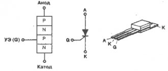
The working part of such equipment is a soldering iron with an inductor installed inside it - a coil of copper wire wound around a socket into which the shank of a replaceable tip with ferromagnetic coating is inserted.
The design of the heating element of an induction station for soldering
The process of heating the tip with an inductor occurs as follows:
- The generator supplies a high-frequency current with a voltage of 36 Volts through the power cable to the inductor coil;
- The current passing through the turns of the inductor generates an alternating magnetic field, the lines of force of which intersect the tip shank located inside the inductor with ferromagnetic coating on the surface;
- The magnetic field, when interacting with the ferromagnetic coating on the tip shank, leads to its magnetization reversal and the formation of eddy currents. This process is accompanied by the release of a large amount of heat and very rapid heating of the shank, the trace and the entire tip to a high temperature.
The current (its frequency, and therefore the temperature of the tip) is adjusted using adjusting encoders on the electronic unit.
Ultrasonic soldering
Ultrasonic soldering is a flux-free soldering technology that does not require any chemicals and uses ultrasonic energy to solder materials such as glass, ceramics, composite materials, and metals that are difficult or impossible to solder using traditional means.
This technology is increasingly used when soldering together metal and ceramic parts included in the design of solar cells, as well as parts made of medical alloys with shape memory used in specialized electronic modules and sensor units.
Ultrasonic soldering has been mentioned since 1955 as a method for soldering aluminum and other metals without the use of flux.
This technology differs significantly from ultrasonic welding. The latter uses ultrasonic energy to join parts without adding any fillers, while traditional (and ultrasonic) soldering uses external heat to form the joint to melt metal fillers, i.e. solders. In this case, ultrasonic soldering can be performed using either a special soldering iron or a special soldering bath.
This process can be carried out either automatically during mass production or manually during prototyping or repair work.
Ultrasonic soldering was originally intended for joining aluminum and other metals, but today, with the advent of active solders, a wider range of metals, ceramics and glass can be soldered.
This technology uses either ultrasonic soldering irons with a tip with a diameter of 0.5-10 mm, or ultrasonic soldering baths. These devices use piezoelectric crystals to generate high-frequency (20-60 kHz) sound waves in layers of molten solder or in a bath of molten solder to mechanically destroy oxide films formed on the surfaces of the melt. In this case, the tips of ultrasonic soldering irons are simultaneously connected to the heating element, while the piezoelectric crystal is thermally insulated to prevent its destruction.
The tips of ultrasonic soldering irons can heat up to 450 °C during mechanical vibrations with a frequency of 20-60 kHz. Such a tip is capable of melting metal fillers of solder by exciting sound vibrations in the molten solder. At the same time, vibration and cavitation (pore formation) in the resulting melt allow solders to wet the surfaces of many metals and adhere to them.
The energy of sound waves generated by the tip of an ultrasonic soldering iron or an ultrasonic solder bath causes cavitation in the molten solder, which mechanically destroys the oxide films located on top of the layers of the solder itself and on the metal surfaces being joined.
Cavitation in a bath of molten solder can very effectively destroy oxide films on the surfaces of many metals, but it is ineffective when soldering to ceramics and glass, since the latter are themselves oxides, as well as to other non-metallic composite materials that cannot be destroyed, since they are base substance. In case of soldering directly to glass and ceramics, metal fillers for ultrasonic soldering must be doped with active elements such as indium (In), titanium (Ti), hafnium (Hf), zirconium (Zr), and rare earth elements (cerium/Ce, lanthanum/La and lutetium/Lu). Solders doped with these chemical elements are called "active solders" because they directly act on glass or ceramic surfaces to create adhesion to them.
Ultrasonic soldering technology is increasingly used due to its cleanliness, lack of flux and compatibility with active solders, and is intended for joining parts that do not allow the use of aggressive flux or consist of dissimilar materials (metals, ceramics or glass).
For effective adhesion to surfaces, the active solder's own oxide film, formed during its melting, must be destroyed, and ultrasonic vibration is well suited for this purpose.
Heating control principle
DIY soldering station
In induction soldering stations, 2 methods are used to control the temperature to which the soldering iron tip is heated:
- Using a temperature sensor built into the tip, a thermocouple placed in the tip sends signals to the electronic unit, which, based on the received data and established adjustments, heats the device tip to a certain temperature;
- Using replaceable tips (cartridges) - most modern models of such soldering devices come with several replaceable tips that have a ferromagnetic coating that loses its magnetic properties at a certain temperature.
On a note. The technology of using replaceable cartridge nozzles with ferromagnetic coating, which ensures heating of the tip to a certain temperature, is a development and is called “Smart heating”, or “Smart heat”.
Replaceable nozzles (cartridges) with ferromagnetic coating
The first method is found in inexpensive semi-professional models. Its main advantages are relative cheapness and ease of adjustment. The second technical solution is used in more expensive, high-quality and reliable models of professional soldering stations.
I have long wanted to buy a station, but due to financial problems the opportunity did not arise, and after a little thought I decided - is it possible to make it with my own hands?
I scoured the net a little and found this video https://www.youtube.com/watch?v=wzGbTwlyZxo. The station is just what I need - controlled by a microcontroller, output of data to a 16x2 LCD display on which it is displayed.
The top line is the set temperature of the soldering iron and the current temperature on it, the data is updated several times per second (0-480°C)
The bottom line is the set temperature of the hair dryer, the current temperature on it (0-480°C), as well as the rotation speed of the fan built into the hair dryer (0-99)
Board and circuit
You can download the printed circuit board (+ circuit diagram and firmware) here, everything is original, like the author.
A few tips for those who are too lazy to watch the videos (although I explained everything in some detail in them)
The dimensions of the printed circuit board have already been established; there is no need to mirror it either. It is advisable to replace the terminals through which the controls are connected to the board, that is, instead of terminals, use the usual method - take the wires and solder them into the corresponding holes on the board.
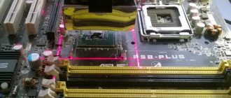
During etching, it is MANDATORY to check sections of the board with the template, since in some places the leads of SMD components can form a short circuit, all this is clearly visible in the photo
An ATMEGA328 type MK is the same microcontroller that is found on programmer boards with an arduino uno kit; in China it costs a penny, but with an MK you will need either a homemade programmer or a native arduino uno, as well as a 16 MHz quartz resonator.
The MK is fully responsible for controlling and outputting data to the LCD display. Control of the station is quite simple - 3 variable resistors of 10 kOhm (the most common, mono - 0.25 or 0.5 watts), the first is responsible for the temperature of the soldering iron, the second is the vein, the third increases or decreases the speed of the cooler built into the hair dryer.
The soldering iron is controlled by a powerful field-effect transistor, through which a current of up to 2 Amps will flow, therefore it will heat up, and the triac will also heat up - it, along with the transistor and a 12-volt stabilizer, was wired to a common heat sink, and the housings of these components were additionally insulated from the radiator.
Be sure to take 3mm LEDs with low consumption (20mA) due to the use of more powerful 5mm LEDs (70mA), my hair dryer did not work, or rather it did not heat up. The reason is that the LED on the board and the LED that is built into the optocoupler (it actually controls the entire heating unit of the hair dryer) are connected in series and there was simply not enough power for the LED in the optocoupler to light up.
Soldering iron
I myself took a Ya Xun soldering iron for stations of this type, 40 watts with a durable tip. The plug has 5 pins (contact holes), the pinout of the plug is below
Please note that the photo shows the pinout of the plug on the soldering iron itself.
The soldering iron has a built-in thermocouple, the data from which is received and decrypted by the station itself. You MUST need a soldering iron with a thermocouple, and not with a thermistor as a temperature sensor.
The thermocouple has polarity; if the thermocouple is connected incorrectly, the soldering iron will reach its maximum temperature after turning on and become uncontrollable.
Hairdryer
In principle, the power can be from 350 to 700 watts, I advise no more than 400 watts,
That's enough for any needs. The hair dryer also has a built-in thermocouple as a temperature sensor. The hair dryer must have a built-in cooler. It has an 8-pin socket, the pinout of the socket on the hair dryer is presented below.
Inside the hair dryer there is a 220 Volt heater itself, a thermocouple, a fan and a reed switch, the latter can be immediately thrown away; it is not needed in this project.
The heater does not have polarity, but the thermocouple and cooler do, so be sure to observe the polarity of the connection, otherwise the motor will not spin, and the heater will reach its maximum temperature and become uncontrollable.
power unit
Any (preferably stabilized adapter) 24 Volts minimum 2 Amperes, I advise 4-5 Amps. Universal chargers for laptops are perfect, they have the ability to adjust the output voltage from 12 to 24 Volts, protection against short circuits and a stabilized output - and it costs a penny, I chose this one myself.
You can also use a low-power power supply for 24 Volt LED strips, available with a current of 1 Ampere.
You can also slightly modify the electronic transformer (as the most budget option) and implement it into the circuit; I explained in more detail about power supplies at the end of the video (part 1)
You can also use a transformer power supply - it may not be stabilized, but I repeat - it is desirable to have stabilization.
Installation and housing
The case is from a Chinese radio, the 16x2 display fits perfectly with it, all controls are installed on a separate plastic sheet and docked to the bottom of the radio.
The main power components are reinforced to the heat sink through additional insulating gaskets and plastic washers. The heat sink was taken from a non-working uninterruptible power supply.
It heats up, but only after working for a long time with a hairdryer at high power, but all this is tolerable, by the way - the board provides an additional 12 Volt output for connecting a Cooper, so that you can blow off the radiator if there is a need for it.
Settings
In principle, to set up you need either a thermometer or a tester with a thermocouple and the ability to measure temperature.
First, you need to set a certain temperature on the soldering iron (for example, 400 degrees), then press the thermocouple to the soldering iron tip to understand the real temperature on the soldering iron tip, and then simply using a trimmer resistor on the board (slow rotation) we achieve to compare the real temperature on the soldering iron (which is displayed) with the one shown by the thermometer.
The same thing needs to be done with a hairdryer, only the thermometer needs to be placed under a stream of hot air.
I highly recommend that you take multi-turn trimmer resistors for convenient and precise adjustment.
By the way, the third trimmer on the board is responsible for the display contrast.
Minuses
To be honest, I didn’t notice, the design is universal, convenient, simple, and at the same time we get a professional soldering station for any needs, for which great respect goes to the author.
Main advantages and costs.
The price category of such stations is around 100 - 150 $, we have full control of a hair dryer and soldering iron and a fairly smart filling that displays all the data on an LCD display; in budget stations, instead of a display, there are ordinary LED indicators.
Smart control system for the hot air gun - when you turn off the hair dryer itself, the cooler will work until the heater cools down, then it will turn off by itself, also a very thoughtful safety solution, which is available on all profs. stations.
It is also possible to adjust the cooler speed.
Both in the case of a hair dryer and in the case of a soldering iron, the maximum temperature is 480 degrees.
On account of costs
- You can buy a soldering iron here
- Hairdryer here
- Hair dryer attachments here
- Arduino board with MK here
- LCD display here
- A set of soldering iron tips is here
- Power supply here
PS this article was published in half an hour, if I missed anything, forgive me.
Choosing the right model
The main criteria for choosing such equipment for soldering are the following:
- Power – the most convenient and practical models of soldering stations are those with adjustable power in the range from 5 to 60 W;
- Frequency of current in the inductor - for radio amateurs and semi-professionals, a device with a current frequency of 400 to 700 KHz is sufficient. Professionals and craftsmen use models with values of this characteristic up to 13.5 MHz;
- Type of heating control - most of the modern equipment of this type is produced with regulation of the heating temperature of the tip using the “Smart heat” technology;
- Number of independent channels – in order to be able to connect, in addition to a soldering iron, thermal tweezers, the device must be equipped with 2 independent channels;
- Dimensions and weight – for convenient operation and carrying, the device should be small in size and weigh no more than 1 kg;
- Also, when choosing, take into account the possibility of post-warranty repair of the device, the availability of additional components that make the soldering process more convenient.
Method of soldering parts with an ultrasonic soldering iron
The method can be used to restore parts by soldering using ultrasound.
The solder is fed in the form of a rod through a hole inside the copper solder rod. The solder is melted by heating the soldering rod with an electric heating coil. The upper part of the end of the soldering rod is made of a spherical shape to smooth the resulting layer of solder. The method allows you to expand technological capabilities while improving the quality of surface treatment of parts. 1 ill. The invention relates to the restoration of parts by soldering, namely in our case, soldering using an ultrasonic soldering iron.
There are many known methods of restoration and manufacturing of parts by soldering, in which ultrasonic soldering irons are used. According to a literary source, a method of soldering with an ultrasonic soldering iron UP-21 is known, which operates at a frequency of 20-26 kHz from an ultrasonic generator. The disadvantages of this method are as follows: solder is supplied to the seam being processed (surface), individually applied to the seam being processed (surface) in the form of a rod, which significantly complicates the soldering work as the time to complete the work increases and the quality of the work performed (soldering) deteriorates.
The closest analogue of the claimed invention is a method for soldering parts with an ultrasonic soldering iron (SU 831447, IPC 7 B 23 K 1/06, 05/30/1961), according to which solder is fed through a hole inside the soldering rod, and it is melted using an electric heating coil.
The objective of the invention is to expand the technological capabilities of soldering seams (surfaces) while reducing the time required to carry out work and improving the quality of processing, as well as providing more convenient work for the performer.
The specified technical result is ensured by the fact that solder in the form of a rod is inserted into the body of the soldering iron (into the ultrasonic vibrator), which, when heated by the electric heating coil, melts and enters the seam (surface) being processed, compacting and interspersing solder elements into the seam (surface) with the help of ultrasonic vibrations , which destroy the oxide film on the surface being processed, and the upper part of the end of the rod, made in a spherical shape, smoothes and incorporates (under its pressure) the applied layer of solder, which ensures the completion of the given task.
The drawing shows a diagram of a device (ultrasonic soldering iron) that ensures the implementation of the proposed method.
The method is carried out as follows. On a machine, on a special installation or on an automatic line for soldering parts, or manually, parts for soldering are installed, previously prepared for soldering according to the technology. Soldering with an ultrasonic soldering iron is carried out using low-temperature solder, which has some features when soldering aluminum parts, which are explained by the formation of a strong and refractory oxide film on the surface of the parts, which prevents the parts from joining. When soldering with this soldering iron, ultrasonic vibrations occur in the molten solder, which destroy the oxide film on the parts. The surfaces of the parts, free of oxides, are well connected to the solder and provide strong soldering.
Example. The parts are soldered using an ultrasonic soldering iron shown in the drawing. Soldering with low-temperature solders is carried out with preliminary preparation of parts for soldering, soldering and processing of parts after soldering. Preparing parts for soldering includes cleaning the edges of parts from contamination and oxides, heating the parts to soldering temperature, fluxing (if necessary) and tinning the surfaces to be joined. Next, the product is assembled, ensuring a gap between them of 0.05-0.20 mm. Then the tip 8 of the ultrasonic vibrator 3, the soldering iron (copper rod 6) is brought to the junction of the parts to be connected 1, where the ultrasonic vibrator 3, operating at a frequency of 20-26 kHz, using the spiral 4 of the ultrasonic generator, supplies ultrasonic vibrations to the molten solder, which, destroying the oxide film on the parts, are connected to solder 2, which is fed in the form of a rod 7 into the hole of the vibrator (which is made along its axis), melted by heating the copper rod 6 using an electric heating coil 5, smoothing the applied layer of solder using a tip 8, ending the process rations.
Low-temperature soldering has become widespread in car repairs, namely in the repair of water and oil radiators, electrical parts of fuel tanks and other parts. The quality of soldering is usually controlled by crimping parts with compressed air or water.
A method for soldering parts with an ultrasonic soldering iron, including supplying solder through a hole inside a soldering rod and melting it by heating the solder rod using an electric heating coil, characterized in that solder is supplied in the form of a rod, and the upper part of the end of the soldering rod is made spherical to smooth the resulting layer solder, using a soldering rod made of copper.
Is it possible to make an induction soldering station with your own hands?
The wide variety of models of such equipment makes its independent production practically impractical and costly; it is easier to buy a simple Chinese device, which at a low cost will have a fairly long service life and good soldering quality.
Therefore, you can make an induction soldering iron with your own hands solely out of scientific interest, having studied the internal structure of such a device and the physical phenomena occurring in it in more detail and clearly.
Homemade equipment
There are a lot of electronics repair specialists, so the demand for pulse soldering irons is quite stable. But still, some try to make such a soldering iron from an electronic transformer with their own hands. The following reasons push them to do this:
- High cost of imported high-quality equipment.
- Poor quality products of Chinese origin.
The simplest high-frequency heater
For a person who is a little familiar with electrical engineering, making a tool is not difficult. For this you will need:
- Transformer.
- Copper shank and wire.
- Material for making a handle.
First you need to find a circuit for a pulse soldering iron. This is easy to do using the Internet.
The primary winding is connected to the power element, and the secondary winding is connected to the sting and signal lamp. This simplicity makes the device reliable and unpretentious in terms of voltage quality. Most inexpensive products are based on just such a scheme.
Manufacturing requires a small-sized power transformer. It can be taken from the power supply of any unnecessary or broken household appliance. Its circuit will be modernized. First you need to carefully open the transformer housing and get close to the winding, which needs to be carefully unwound. A new primary winding is wound from the wound wire at 1300 revolutions. This can be done manually or on a special winding machine.
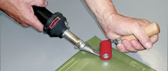
Taking measurements using an induction soldering station
Monitoring soldering temperature using a thermocouple and multimeter
When soldering various small radio components, in accordance with the requirements of various regulatory documents, recommendations of manufacturers of electronic components, safety precautions, the temperature of the tip when it touches the working surface should not be higher than 2700C. When working with the described soldering equipment, this indicator is set using adjusting encoders on the electronic unit of the device. Check the correctness of this setting by touching the tip of the device with the tip of a thermocouple connected to a multimeter.
Types of household soldering irons
A soldering iron is an electrical tool that is designed to connect metal elements together using solder. Metal alloys based on copper, tin, lead, etc. are used as solder.
The simplest soldering iron consists of the following elements (Fig. 1):
Figure 2. Diagram of a mini-soldering iron with a nichrome heating element.
- sting;
- kernel;
- heater;
- frame;
- pen;
- power cord with plug.
The rod and tip are made of red copper. This is due to the fact that this material has high thermal conductivity, due to which the heat from the heating element (nichrome spiral thread) is freely transferred to the solder, resulting in metal soldering.
In addition to a tool with a spiral heating element (EPSN), there are also other types of soldering irons, among which the most popular are:
- Induction. The principle of its operation is based on an inductor element. A magnetic field is generated around the ferromagnetic core using an inductor, which leads to heating of the tip.
- Ceramic. In this tool, the working element is a ceramic rod, which heats up when an electric current is applied to it. Ceramic products are characterized by high efficiency, rapid heating of the tip, the ability to adjust the output temperature and durability.
- Pulse. Such a soldering iron looks like a gun, which is put into operation by holding down the start button. The main advantage of a pulse tool is the almost instantaneous heating of the tip (within 4-6 s).
- Rechargeable. A battery is used as a power source. The power of such a product is about 16 W, so it can only solder simple electronic elements.
Additional equipment
In some models of this soldering equipment, the extended package includes the following tools and accessories:
- Thermal tweezers;
- Soldering iron holder;
- A set of replaceable nozzles for different temperatures.
Also, some expensive soldering stations have a small display on the electronic unit that displays the temperature of the device tip.
Thus, a soldering station with an inductor heater is equipment that has many advantages. This makes it in demand and popular among both specialists and ordinary radio amateurs.
What equipment is used for soldering
Soldering is considered one of the most effective and reliable methods of joining materials.
Previously, it was used for metals and their alloys, but soldering is also suitable for joining pieces of glass, plastic, and ceramics. There are many types of soldering, each of them uses special soldering equipment, tools and devices.
Soldering iron
The most commonly used tool for soldering work is a soldering iron. It’s hard to imagine workplace equipment without it. Soldering irons are used by amateurs and professionals. It all depends on the type of instrument.
Hammer
To connect large, massive parts, hammer soldering irons are used, so named because of their hammer-like shape. They are heated in ovens or braziers and, having great thermal inertia, remain heated for a long time.
Such equipment is used for soldering large parts.
Electric
The most traditional soldering method is with an electric soldering iron. It is designed very simply - a metal casing contains a heating element that heats the tip - a copper rod. The heating temperature of the soldering iron depends on the power of the heating element.
The process of soldering work consists in heating the parts to be connected using a contact method and holding them together with a special compound called solder. After cooling, a strong connection is obtained that can conduct electricity if the parts being connected are conductors.
A professional electric soldering iron can be equipped with a voltage regulator. In this case, it is possible to adjust the temperature of the tip, which is very important when assembling and installing electronic circuits.
Induction equipment is of particular interest. Induction soldering irons self-regulate heating and use electricity economically.
They produce ultrasonic soldering equipment. The ultrasonic soldering iron is equipped with a generator that produces a high-frequency signal.
In addition to a soldering iron operating from a household network, the soldering station equipment may include a soldering tool powered by 12 or 24 volts. It is suitable for debugging the operation of electronic circuits and for mounting parts and components that may fail due to overheating.
Electric soldering irons can also be cordless, powered by AA batteries.
Gas
Gas soldering irons are very convenient to use; they are heated by gas combustion. Gas equipment is represented by a huge number of models, differing in size, ignition system, and the presence of a temperature regulator.
Using gas soldering equipment, you can melt high-temperature hard solders. They produce stations for gas soldering of copper pipes, which include cylinders, reducers, a platform and a burner.
The disadvantages of electric or gas soldering irons are the inability to simultaneously heat a large area at low power. In this case, other types of equipment are used.
Infrared stations and hair dryers
Models of hot-air soldering equipment (hair dryers) are used mainly for dismantling and volumetric mounting of microcircuits on electronic device boards. Very often, a hair dryer is included in the package of a soldering station, which also consists of an electric soldering iron and a control unit.
The soldering station allows you to install and control the parameters of the tools included in it, ensuring high quality seams.
Often, the equipment for a soldering station includes a table with the ability to heat parts or circuit boards from below.
This installation uses infrared heat sources - lamps, heating elements. Some designs of heating tables are equipped with brackets and stands, which allow you to secure the boards.
Infrared equipment has a similar effect to a soldering gun. It can also be used to provide heating of a large area without allowing contact with microcircuit elements.
Infrared soldering stations allow you to control soldering and ensure smooth cooling of the metal. This is expensive equipment, which consists of entire computing systems with sets of sensors, processors and a whole list of auxiliary tools.
Tools and accessories
When manual soldering, it is not enough to have only soldering equipment. Without the necessary additional devices, it is sometimes impossible to solder anything, not just efficiently, but at all. Such devices include:
- blowtorch;
- tweezers;
- set of files;
- wire cutters;
- magnifying glass and tripod;
- clamps;
- stands.
How to make your own “Moment” soldering iron from a house-saving lamp
It is necessary to find used components from old household electrical appliances:
- Converter (ballast) from a fluorescent lamp. Enough power 40 W;
- Working transformer;
- Copper wire 2-3 mm in diameter;
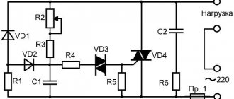
The case, or rather the manufacturing technology, is not important. Device diagram:
In fact, everything that we see on the circuit diagram to the left of transformer Tr1 is part of the ballast from the energy-saving lamp. The device is complete; there is no need to modify it or change components.
The characteristics of the converter are quite suitable for a medium-power pulsed soldering iron. The safety of the design is enhanced by a standard fuse and overheating control using a thermistor. The circuit turns out to be compact and can be placed in any housing.
The working transformer is made independently. A ferrite ring from a broken electronic transformer is suitable for this. The size must be sufficient to accommodate the windings. We wind the primary from 0.5 mm wire. The number of turns is 100-120.
The secondary (power) winding is made of wire with a cross-section of 3-3.5 squares. We make one turn. A soldering iron tip made of copper or nichrome wire 1.5 - 2 mm is attached directly to it.
IMPORTANT! The thickness of the secondary winding must be greater than the thickness of the tip.
A pulsed soldering iron made from an energy-saving lamp is ready. All that remains is to come up with a convenient housing for it, install a switch, and you can quickly repair electrical appliances.