Thyristor
A thyristor is a switching semiconductor device that passes current in one direction.
This radio element is often compared to a controlled diode and is called a semiconductor controlled rectifier (SCR). The thyristor has three outputs, one of which - the control electrode, one might say, the “trigger” - is used to abruptly switch the thyristor to the on state.
The thyristor combines the functions of a rectifier, switch and amplifier. It is often used as a regulator, mainly when the circuit is powered by alternating voltage. The following points reveal the four main properties of a thyristor:
- A thyristor, like a diode, conducts in one direction, acting as a rectifier;
- The thyristor is switched from the off state to the on state when a signal is applied to the control electrode and, therefore, like a switch, has two stable states. However, to return the thyristor to the off (open) state, special conditions must be met;
- the control current required to transfer the thyristor from a closed state to an open state is significantly less (several milliamps) with an operating current of several amperes and even several tens of amperes. Consequently, the thyristor has the properties of a current amplifier;
- oThe average current through a load connected in series with a thyristor can be precisely adjusted depending on the duration of the signal at the control electrode. The thyristor is a power regulator.
Thyristor structure
A thyristor is a controlled three-electrode semiconductor device consisting of alternating four silicon layers of type p and n. A semiconductor device with a four-layer structure is shown in Fig. 1.
The extreme region of the p-structure, to which the positive pole of the power source is connected, is usually called the anode, and the extreme region n, to which the negative pole of this source is connected, is called the cathode.
Fig.1. Thyristor structure and designation
Equivalent to low voltage gas arrester
In Fig. Figure 7 shows a diagram of a device equivalent to a low-voltage gas discharger [PTE 4/83-127]. This device is a gas-filled cylinder with two electrodes, in which an electrical interelectrode breakdown occurs when a certain critical voltage value is exceeded.
The “breakdown” voltage for an analogue of a gas spark gap (Fig. 7) is 20 V. In the same way, an analogue of, for example, a neon lamp can be created.
Rice. 7. Analogue of a gas discharger - equivalent replacement circuit.
Properties of the thyristor in the closed state
According to the structure of the thyristor, three electron-hole junctions can be identified and the thyristor can be replaced with an equivalent circuit, as shown in Fig. 2.
This equivalent circuit allows us to understand the behavior of the thyristor with the control electrode disconnected.
If the anode is positive with respect to the cathode, then diode D2 is closed, which leads to the closure of the thyristor, which in this case is forward biased. With a different polarity, diodes D1 and D2 are reverse biased, and the thyristor is also turned off.
Fig.2. Representation of a thyristor by three diodes
Why is verification needed?
In the process of repairing or assembling a new circuit, it is impossible to do without electrical parts. One of these parts is a triac. It is used in alarm circuits, light controllers, radio devices and many branches of technology. Sometimes it is reused after dismantling non-working circuits, and it is not uncommon to encounter an element whose markings have been lost due to long-term use or storage. It happens that new parts need to be checked.
How can you be sure that the triac installed in the circuit is really working, and in the future you will not need to spend a lot of time debugging the operation of the assembled system?
To do this, you need to know how to test a triac with a multimeter or tester. But first you need to understand what this part is and how it works in electrical circuits.
In fact, a triac is a type of thyristor. The name is made up of these two words - “symmetrical” and “thyristor”.
Opening principle using a control electrode
An equivalent representation of the p-npn structure in the form of two transistors is shown in Fig. 3.
Representing a thyristor in the form of two transistors of different conductivity types leads to the equivalent circuit shown in Fig. 1.4. It clearly explains the phenomenon of thyristor unlocking.
Let us set the current IGT through the control electrode of the thyristor, biased in the forward direction (voltage VAK positive), as shown in Fig. 4.
Since the IGT current becomes the base current of the npn transistor, the collector current of this transistor is equal to B1xIGT, where B1 is the current gain of transistor T1.
This current is also the base current of the pnp transistor, which leads to its unlocking. The collector current of transistor T2 is B1xB2xIGT and is summed with the current IGT, which maintains transistor T1 in the open state. Therefore, if the IGT drive current is large enough, both transistors will go into saturation.
The internal feedback circuit maintains the conductivity of the thyristor even if the initial current of the IGT control electrode disappears, while the anode current (1A) remains quite high.
A typical thyristor startup circuit is shown in Fig. 5
.
Fig.3. Splitting a thyristor into two transistors
Fig.4. Representation of a thyristor as a two-transistor circuit
Fig.5. Typical thyristor trigger circuit
Peculiarities
To have a complete understanding of symmetrical thyristors, it is necessary to talk about their strengths and weaknesses. The first include the following factors:
- relatively low cost of devices;
- long service life;
- lack of mechanics (that is, moving contacts that are sources of interference).
The disadvantages of the devices include the following features:
- The need for heat removal is approximately at the rate of 1-1.5 W per 1 A, for example, at a current of 15 A, the power dissipation value will be about 10-22 W, which will require an appropriate radiator. For ease of fastening to it for powerful devices, one of the terminals has a thread for a nut.
Triac with radiator mount
- Devices are subject to transients, noise and interference;
- High switching frequencies are not supported.
The last two points require a little clarification. In the case of high switching speed, there is a high probability of spontaneous activation of the device. Interference in the form of a voltage surge can also lead to this result. To protect against interference, it is recommended to bypass the device with an RC circuit.
RC circuit to protect the triac from interference
In addition, it is recommended to minimize the length of the wires leading to the controlled output, or alternatively use shielded conductors. It is also practiced to install a shunt resistor between the T1 terminal (TE1 or A1) and the control electrode.
Thyristor shutdown
The thyristor will go into the closed state if no signal is applied to the control electrode of the open thyristor, and its operating current drops to a certain value called the holding current (hypostatic current).
The thyristor will turn off, in particular, if the load circuit was open (Fig. 6a) or the voltage applied to the external circuit changed polarity (this happens at the end of each half-cycle of the alternating supply voltage).
Fig.6. Methods for turning off a thyristor
When the thyristor operates at constant current, switching off can be done using a mechanical switch.
Connected in series with the load, this switch is used to disconnect the operating circuit.
A switch connected in parallel to the main electrodes of the thyristor (Fig. 6b) shunts the anode current, and the thyristor goes into the closed state. Some thyristors turn on again after the switch is opened. This is explained by the fact that when the switch is opened, the parasitic capacitance of the p-n junction of the thyristor is charged, causing interference.
Therefore, they prefer to place the switch between the control electrode and the cathode of the thyristor (Fig. 1.6c), which guarantees correct shutdown by cutting off the holding current. At the same time, the p-n junction corresponding to diode D2 from the thyristor equivalent circuit with three diodes is reverse-biased (Fig. 2).
In Fig. 6a-e show various options for thyristor shutdown circuits, including those previously mentioned. Others are usually used when it is necessary to turn off the thyristor using an additional circuit. In these cases, the mechanical switch can be replaced by an auxiliary thyristor or a key transistor, as shown in Fig. 7.
Fig.7. Classic thyristor shutdown circuits using an additional circuit
How to avoid false positives
Since a small potential is enough to trigger a triac, false alarms are possible. In some cases, they are not terrible, but they can also lead to damage. Therefore, it is better to take action in advance. There are several ways to reduce the likelihood of false inclusions:
- Reduce the length of the line to the gate, connect the control circuit - gate and T1 - directly. If this is not possible, use shielded cable or twisted pair.
- Reduce shutter sensitivity. To do this, place a resistance in parallel (up to 1 kOhm).
In almost all circuits with triacs, there is a resistor in the gate circuit that reduces the sensitivity of the device
- Use triacs with high noise immunity. They have the letter “N” added to their labeling, for “insensitive”. They are called “H-series triacs”. They differ in that the minimum transition current is much higher. For example, a BT139-600H triac has a transition current IGT min =10mA.
As already said, the triac is controlled by current. This makes it possible to connect it directly to the outputs of the microcircuits. There is one limitation - the current should not exceed the maximum permissible. Typically this is 25 mA.
Triac
SIMCMOP is a semiconductor device that is widely used in systems powered by alternating voltage. In simple terms, it can be considered as a controlled switch. When closed, it behaves like an open switch. On the contrary, the supply of control current to the control electrode of the triac leads to its transition to a conducting state. At this time, the triac is like a closed switch.
In the absence of control current, the triac inevitably passes from the conduction state to the closed state during any half-cycle of the alternating supply voltage.
In addition to operating in relay mode in a thermostat or photosensitive switch, control systems have been developed and are widely used that operate on the principle of phase control of the load voltage, or, in other words, smooth regulators.
Element testing
There are several ways to test a triac for functionality. For the simplest, you will only need a multimeter, and for more complex measurements, an autonomous power supply or test circuit.
With the help of a tester, testing occurs using knowledge based on the operating principle of a triac. Diagnostics with a multimeter will not be able to determine all the characteristics of the element, but it will be quite sufficient for initial performance testing.
A simple test can be done using a light bulb and a battery. To do this, one terminal of the battery is connected to the control and operating terminals of the triac, and the second to the base of the light bulb. The element's output is connected to the central contact of the illuminator. In this case, the transition must be open, then the light will light up.
Checking with a tester
A device of any type of action is suitable for carrying out tests, but it is necessary that the value of the current it produces is sufficient to switch the element. Therefore, it would be more preferable to use an analog device. For example, to test the BTB12-800CW tester, you will need to provide a current of about 30 mA, and for the BTB16-700BW this figure should be 15 mA.
You will also need to pay attention to the condition of the battery in the tester. In a digital device, the battery replacement icon should not be displayed on the screen, and in an analog device, when the probes are short-circuited to each other, the arrow should point to zero
The essence of the measurement comes down to checking the transitions of the device. To do this, the tester switches to resistance testing mode at the smallest range. It is best to perform the check in the following sequence:
- Test leads are connected to the power terminals of the triac T1 and T2. If the radio element is working properly, then the multimeter should show an infinitely high resistance.
- The polarity of the applied signal at the working terminals changes. To do this, the measuring probes are rearranged. The resistance must also be high.
- The operating terminal T1 or T2 and the control electrode G are briefly connected.
- Again the junction resistance between T1 and T2 is measured. It should change in one direction. So, for BTB12-800CW it will be about 50 Ohms.
- The polarity changes. In this case, the junction impedance should be high, which corresponds to the absence of reverse breakdown.
Using a schema
There are many different schemes used by radio amateurs to test the performance of a triac. But it is better to use a universal circuit that can test any element of the thyristor family, for example, BTB16-700BW. It does not require configuration and works immediately after assembly. In order to assemble it, you will need the following elements:
- Resistors R1—R4 470 Ohm, R4—R5 1 kOhm.
- Capacitors C1 and C2 - 100 µF x 6.5 V.
- Diodes VD1, VD2, VD5 and VD6 - 2N4148; VD2 and VD3 - AL307.
A KRONA type battery can be used as a power source.
The essence of the measurements comes down to the following actions: switch S3 is moved to the upper position, as a result, power is supplied to the device. After this, by briefly pressing the S2 button, current is supplied to the control output of the element.
If the BTB16-700BW is working, then its junction should open, which will be signaled by the VD3 LED. Then the switch is set to the middle position, the LED should go out. In the next step, S3 is switched to the down position and button S2 is pressed. The result of these actions will be the lighting of the VD4 LED. This behavior of the triac will allow us to declare with 100% confidence that it is working.
Checking a triac is not so difficult, especially if you use a tester, although it is better to assemble a special circuit. But it is worth noting that due to the high sensitivity of triacs to switching current, it is better to use pointer instruments as multimeters.
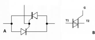
Triac unlocking
In alternating power mode, a change in the states of the triac is caused by a change in the polarity of the voltage on the working electrodes A1 and A2. Therefore, depending on the polarity of the control current, four options for controlling the triac can be defined, as shown in Fig. 9.
Each quadrant corresponds to one way of opening the triac. All methods are briefly described in table. 1.
Fig.9. Four possible triac control options
Table 1. Simplified representation of methods for opening a triac
| Quadrant | VA2-A1 | VG-A1 | I.G.T. | Designation |
| I | >0 | >0 | Weak | + + |
| II | >0 | Average | + — | |
| III | Average | — — | ||
| IV | >0 | High | — + |
For example, if a voltage VA1-A2>0 is applied between the working electrodes of a triac and the voltage on the control electrode is negative with respect to the anode A1, then the bias of the triac corresponds to quadrant II and the simplified designation + -.
For each quadrant, the unlocking current I from (IGT), the holding current Iud (In) and the switching current Ioff (IL) are determined.
The unlocking current must be maintained until the operating current exceeds two to three times the holding current In. This minimum unlocking current is the turn-on current of the triac IL.
Then, if the current through the control electrode is removed, the triac will remain in a conducting state as long as the anode current exceeds the holding current In.
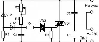
Soldering iron power control circuit
In conclusion, we present a simple circuit that allows you to control the power of the soldering iron.
Simple power regulator for soldering iron
Designations:
- Resistors: R1 – 100 Ohm, R2 – 3.3 kOhm, R3 – 20 kOhm, R4 – 1 Mohm.
- Capacitances: C1 - 0.1 µF x 400V, C2 and C3 - 0.05 µF.
- Symmetrical thyristor BTA41-600.
The above diagram is so simple that it does not require configuration.
Now let's look at a more elegant option for controlling the power of a soldering iron.
Power control circuit based on a phase regulator
Designations:
- Resistors: R1 – 680 Ohm, R2 – 1.4 kOhm, R3 – 1.2 kOhm, R4 and R5 – 20 kOhm (dual variable resistance).
- Capacitances: C1 and C2 – 1 µF x 16 V.
- Symmetrical thyristor: VS1 – VT136.
- DA1 phase regulator microcircuit – KP1182 PM1.
Setting up the circuit comes down to selecting the following resistances:
- R2 – with its help we set the minimum temperature of the soldering iron required for operation.
- R3 – resistor value allows you to set the temperature of the soldering iron when it is on the stand (switch SA1 is activated),