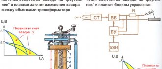
History of invention
In 1873, the English scientist Frederick Guthrie developed the operating principle of directly heated vacuum tube diodes.
A year later, in Germany, physicist Karl Ferdinand Braun suggested similar properties in solid-state materials and invented a point rectifier. In early 1904, John Fleming created the first complete tube diode. He used copper oxide as the material for its manufacture. Diodes have begun to be widely used in radio frequency detectors. The study of semiconductors led to the invention of the crystal detector in 1906 by Greenleaf Witter Pickard.
In the mid-30s of the 20th century, the main research of physicists was aimed at studying the phenomena occurring at the metal-semiconductor contact boundary. Their result was the production of a silicon ingot with two types of conductivity. While studying it, in 1939, the American scientist Russell Ohl discovered a phenomenon later called the pn transition. He found that depending on the impurities existing at the interface of two semiconductors, the reducibility changes. In the early 50s, Bell Telephone Labs engineers developed planar diodes, and five years later, germanium-based diodes with a transition of less than 3 cm appeared in the USSR.
The inventor of the rectifier bridge circuit is considered to be an electrical engineer from Poland, Karol Pollak. Later, the results of Leo Graetz’s research were published in the journal Elektronische Zeitung, so in the literature one can also find another name for a diode bridge - circuit or Graetz bridge.
Design and structure of the rectifier
To smooth out the received rectified voltage pulses, a leveling filter consisting of capacitors, chokes and resistances is connected after the output of the rectifier. To equalize and regulate the resulting current and voltage, a stabilizer circuit is connected to the output of the smoothing filter. Such devices are often connected to alternating current at the input of the device.
The operating modes and properties of the individual components of the rectifier, stabilizer, regulator and filter are coordinated with the specific operating conditions of the consumer load. Therefore, the main task when designing rectification devices is to calculate relationships that make it possible to determine the electrical properties and parameters of the stabilizer components and other parts based on the consumer’s operating mode. Next, you need to calculate these elements and select them from the catalog in the retail chain.
Operating principles of rectifiers
The operation of rectifier devices is based on the property of one-way conductivity of elements. This can be done in different ways. Many industrial applications have become a thing of the past - for example, the use of mechanical synchronous machines or electric vacuum devices. Now valves are used that conduct current in one direction. Not long ago, mercury devices were used for high-power rectifiers. At the moment, they are practically replaced by semiconductor (silicon) elements.
What types of rectifiers are there?
The construction of devices that rectify alternating current is based on the function of the final unit. If it is only necessary to equalize vibrations, assembly on printed circuit boards is carried out using uncontrolled semiconductor elements - diodes. This is how the simplest leveling elements are built.
If it is necessary to change the level of power that is transmitted to the receiving equipment, the device is assembled using controlled valves (thyristors). These rectifiers are required to operate some electrically powered motors. By adjusting the supplied voltage, the rotation speed of the rotor changes.
N-phase rectifiers
Such devices have more than 3 phases for current rectification. Other design features vary. A multiphase rectifier can consist of either a full bridge or a quarter and half bridge. Based on the number of inputs and parallelization, they are divided into separate ones, united by stars or rings. In addition, there are sequential types.
Multiphase rectifiers
Typically, the electrical network has single-phase or three-phase electricity. However, in an industry such as electrical engineering, multiphase voltage is also used. We are talking about a situation where the number of phases is more than three. In this case, rectifiers are used, which are called N-phase.
They work with them in the same way as with three-phase ones. Almost always, bridge circuits in the required quantity are used for this purpose. The classification of rectifiers for this case includes devices that are separate for each phase, connected by a ring or star, and also in series.
Classification by purpose and device
AC generator
AC rectifiers are divided into several different types, depending on the characteristics, the use of alternating current periods, circuits, the number of phases and the type of transmitting element. In general, the classification is as follows:
- By the number of periods involved in the work (one- and two-half-wave, as well as with full and incomplete use of the wave);
- By type, devices are divided into those that include an electronic bridge, voltage multipliers, with or without transformers;
- Based on the number of phases, they are divided into single-phase, two-phase, three-phase and N-phase;
- According to the type of device that transmits a sine wave, they are divided into semiconductor diode and thyristor, mechanical and vacuum, mercury;
- Based on the type of transmitted waves, they are divided into pulsed, analog and digital.
Application benefits
The use of rectifiers by users is beneficial for the following reasons:
- The required basic parameters of the output voltage are set.
- The quality of the incoming power supply improves.
- A high efficiency of the equipment is ensured.
- Voltage ripple is reduced.
- The rectifier device can be used for a single-phase or three-phase network, depending on its structural diagram.
- The high efficiency of converting devices is combined with compactness and relatively low weight. Some models even provide remote control capabilities.
- The rectifier in most cases has negligible reactance.
Operating principle of a half-wave rectifier
In this example, resistance RL represents the load, although in reality the load could be any element or group of elements that could cause a voltage drop.
Half-wave rectifier circuit
During the first half of the AC cycle, diode D1 is in a direct-connected state—a positive electrical potential is applied to its anode and a negative potential is applied to its cathode. When D1 is in the direct-connected state, current flows from the negative side of the transformer secondary, through the load resistance, through the diode, back to the positive side of the secondary. As current flows through the load resistance, a voltage drop occurs across it; The current leaving the rectifier circuit appears as a positive half-wave across the load resistance.
The current path through the half-wave is in the direct connection state D1
During the second half of the AC cycle, diode D1 is in a reverse-connected state—its anode is exposed to a negative electrical potential and a positive electrical potential is exposed to its cathode. This diode does not conduct, so no voltage is present in the load resistance RL.
We recommend reading: All about bipolar transistors: principles of operation and mode of operation, switching circuits and methods of testing for functionality
Half-wave rectifier in reverse conduction state D1
As can be seen from the shape of the curve, half-wave rectifiers have only one half-wave of DC output for each full cycle of AC input. For this reason, equipment usually does not use half-wave rectifiers; When used, they are usually installed in equipment or circuits where low voltage current is required and where voltage fluctuations are not a cause for concern.
Full Wave Rectifier Output Waveform
Operating principle
The operating principle of a three-phase rectifier
The operating principle of any sinusoidal voltage converter is based on the rectifying properties of a special semiconductor element - a germanium or silicon diode. When alternating current flows through it, the positive half-wave freely “passes” through the working electronic junction, biased in the forward direction. When exposed to a negative half-wave, the electrons encounter an obstacle in the form of a potential barrier, so that current cannot flow through the junction.
In the simplest switching circuits, an incomplete cycle of processing variable levels is used, since the second half-wave is irretrievably lost. This significantly reduces the converted power. To preserve the useful component, 2-half-wave rectification circuits were developed, in which the number of diodes was increased to two.
A “full cycle circuit” may contain 4 rectifier elements, but such a circuit belongs to the bridge category.
Electrical parameters
Each type of diode has its own operating and maximum permissible parameters, according to which they are selected for operation in a particular circuit:
- Irev – constant reverse current, µA;
- Upr – constant forward voltage, V;
- Ipr max – maximum permissible forward current, A;
- Urev max – maximum permissible reverse voltage, V;
- Р max – maximum permissible power dissipated by the diode;
- Operating frequency, kHz;
- Operating temperature, C.
Not all diode parameters are given here, but, as a rule, if you need to find a replacement, then these parameters are sufficient.
Circuit of a simple AC rectifier using one diode
We will apply AC mains voltage to the input of the rectifier, in which positive half-cycles are highlighted in red and negative half-cycles are highlighted in blue. We will connect a load (Rн) to the output of the rectifier, and a diode (VD) will perform the function of the rectifying element. With positive half-cycles of voltage applied to the anode of the diode, the diode opens.
At these moments of time, a forward diode current Ipr flows through the diode, and therefore through the load (Rн), powered by the rectifier (the half-cycle wave is shown in red in the right graph). With negative half-cycles of voltage supplied to the anode of the diode, the diode closes, and a slight reverse diode current (Irev) will flow throughout the entire circuit. Here, the diode seems to cut off the negative half-wave of the alternating current (in the right graph, such a half-wave is shown by a blue dotted line).
As a result, it turns out that through the load (Rн), connected to the network through a diode (VD), it is no longer alternating current, since this current flows only in positive half-cycles, and the pulsating current is a current of one direction. This is AC rectification. But this voltage can only power a low-power load that is powered by an AC mains and does not have any special power requirements, for example, an incandescent lamp.
Voltage will only pass through the lamp during positive half-waves (pulses), so the lamp will flicker faintly at a frequency of 50 Hz. However, due to thermal inertia, the filament will not have time to cool down in the intervals between pulses, and therefore the flickering will be faintly noticeable. If we power a receiver or power amplifier with this voltage, then in the loudspeaker or speakers we will hear a low-pitched hum with a frequency of 50 Hz, called AC hum. This will happen because the pulsating current, passing through the load, creates a pulsating voltage in it, which is the source of the background.
This drawback can be partially eliminated if a high-capacity filtering electrolytic capacitor (Cf) is connected in parallel with the load. Charging with current pulses during positive half-cycles, the capacitor (Cf) during negative half-cycles is discharged through the load (Rн)
. If the capacitor is of sufficiently large capacity, then during the time between current pulses it will not have time to completely discharge, which means that the load (Rн) will continuously maintain current both during positive and negative half-cycles. The current maintained by charging the capacitor is shown in the right graph as a solid wavy red line.
Power rectifier diode But even with such a somewhat smoothed current, it is also impossible to power a receiver or amplifier because they will “phon”, since the level of pulsation (Upulse) is still very noticeable. In the rectifier, the operation of which we have become acquainted with, the energy of only half of the alternating current waves is usefully used, therefore more than half of the input voltage is lost on it and therefore such rectification of alternating current is called half-wave, and rectifiers are called half-wave rectifiers. These shortcomings are eliminated in rectifiers using a diode bridge.
General characteristics of rectifier diodes.
Depending on the value of the maximum permissible forward current, rectifier diodes are divided into small
,
medium
and
high
power:
low power
designed for direct current rectification up to 300mA;
average power
– from 300mA to 10A;
high power
- more than 10A.
According to the type of material used, they are divided into germanium
and
silicon
, but today
silicon
rectifier diodes are most widely used due to their physical properties.
Silicon diodes, compared to germanium diodes, have many times lower reverse currents at the same voltage, which makes it possible to obtain diodes with a very high permissible reverse voltage, which can reach 1000 - 1500V, whereas for germanium diodes it is in the range of 100 - 400V .
The performance of silicon diodes remains at temperatures from -60 to +(125 - 150)º C, and germanium diodes - only from -60 to +(70 - 85)º C. This is due to the fact that at temperatures above 85º C the formation of electronic hole pairs becomes so significant that there is a sharp increase in the reverse current and the efficiency of the rectifier decreases.
Application of diodes
One should not think that diodes are used only as rectifiers and detectors. In addition, you can highlight many more of their professions. The current-voltage characteristics of diodes allow their use where nonlinear processing of analog signals is required. These are frequency converters, logarithmic amplifiers, detectors and other devices. Diodes in such devices are used either directly as a converter or form the characteristics of the device when included in the feedback circuit. Diodes are widely used in stabilized power supplies, as reference voltage sources (zener diodes), or as switching elements of storage inductors (pulse voltage stabilizers).
Rectifier diodes.
We recommend reading: Total power of a transformer: what is it, what parts does it consist of, calculation method
Using diodes it is very easy to create signal limiters: two diodes connected back-to-back - in parallel serve as excellent protection for the input of an amplifier, for example, a microphone, from supplying an increased signal level. In addition to the listed devices, diodes are very often used in signal switches, as well as in logic devices. It is enough to recall the logical operations AND, OR and their combinations. One type of diode is LED. Once upon a time they were used only as indicators in various devices. Now they are everywhere, from the simplest flashlights to TVs with LED backlighting, it is simply impossible not to notice them.
Features of a three-phase bridge and options for its construction
Bridge circuits of three-phase rectifiers have design options that make it possible to improve the parameters of the device. They can be improved by introducing additional valve elements. They are equipped with 6, 9 or even 12 rectifier diodes connected in a star or delta circuit.
The more phases (or pairs of diodes) are used in the rectifier circuit, the lower the level of output voltage ripple.
As an example, consider a device with 12 rectifier diodes. One of the groups of 6 pieces is included in this case according to the “star” circuit with a common zero point, and the second - in a triangle (without ground). Taking into account the fact that the rectifiers are connected in series, the potentials at the system output are summed up, and the ripple frequency in the load turns out to be 12 times greater than the network value (50 Hertz). After filtering, the voltage supplied to the consumer is of higher quality.
Diode bridge circuit
One of the most important parts of electronic devices powered by a 220 volt AC network is the so-called diode bridge. A diode bridge is one of the circuit solutions on the basis of which the AC rectification function is performed.
As you know, most devices require direct current rather than alternating current to operate. Therefore, there is a need for rectification of alternating current.
For example, the power supply, which has already been discussed on the pages of the site, contains a single-phase full-bridge rectifier - a diode bridge. In the circuit diagram, the diode bridge is depicted as follows.
Diode bridge circuit
This is a so-called single-phase bridge rectifier, one of several types of rectifiers that are actively used in electronics. It is used to produce full-wave rectification of alternating current.
In hardware it looks like this.
Diode bridge made of individual diodes S1J37
This circuit was invented by the German physicist Leo Graetz, therefore this circuit solution is sometimes called the “Graetz circuit” or “Graetz bridge”. In electronics, this circuit is currently used everywhere. With the advent of cheap semiconductor diodes, this circuit began to be used more and more often. Now you won’t surprise anyone with it, but in the era of radio tubes the “Graetz bridge” was ignored, since it required the use of as many as 4 tube diodes, which were quite expensive at that time.
Calculation of a bridge rectification circuit
The specified or known values are the voltage at the load (Uav.set, current through the load Iav, ripple factor of the rectified voltage Kp.set at the output, voltage and frequency of the supply network.
The calculated values are determined by the formulas:
A valve with permissible reverse voltage is selected from the directory
Urev ≥ 1.6 Uav.r
and current through the valve
I'avg ≥ 0.6Iavg
Next, the electrical quantities characterizing the secondary winding of the transformer are calculated:
UII=(1.1÷1.3)Uav.r III = 0.8Iav; PII=UIIII
In order to obtain a flat external characteristic, it is advisable to choose a filter starting with inductance.
Voltage ripple coefficient at the filter input
Kp.in = 0.67.
Smoothing factor
At a load current of up to 200 mA, the capacitance value of the filter link does not exceed 8–12 μF. Having specified the filter link capacitance Cf, we can determine the inductance of the filter choke
(208)
The capacitance of capacitor C1 shunting the inductor is calculated by the formula
(209)
Capacitor C1 must be designed for operating voltage
Uwork = 4πƒLдрIср
In conclusion, you need to determine the calculated (overall) power of the power transformer using the formula
What is a rectifier used for?
It is convenient to use alternating current for transmission and transportation of electricity. However, electrical appliances are often designed to use direct current. In order to convert alternating current into direct current, various rectification circuits are used. In particular, converting devices are needed for:
- formation of input voltage in high-voltage power plants. This is necessary, for example, for traction substations intended for electrolysis installations, powerful DC motors.
- automatic gain adjustment. The converting device allows you to obtain a constant signal, as well as information about the existing signal level and determines the required gain.
- smoothing out too sharp and sometimes random voltage fluctuations. This input current rectification is used for both household and industrial purposes. It ensures that even in the event of a malfunction in the supply network, the output current and voltage will be generated to ensure good and correct operation of the equipment.
The current rectifier is also used to detect modulated signals. Since more and more electricity is needed in everyday life and to solve production problems, substations are being modernized so that they operate more efficiently. Sometimes this leads to various distortions of the incoming AC voltage. In this case, it is beneficial for the consumer to independently install and use rectifiers, which are also called stabilizers.
Bridge Circuit Operation
Understanding electrical measuring instruments
The device consists of four semiconductor gates combined into a bridge. In this case, the secondary winding of the transforming device is combined with the opposite arms of the diode bridge. The load resistors will be connected via other shoulders. In this case, the output characteristics are significantly higher than those of two-period ones, due to the flow of the entire wave of alternating current voltages through the device.
During the positive half-wave, the signal moves from the negative part of the secondary winding of the transforming device through the valves and load resistor to the positive part of the set of turns of the transforming device. With a negative half-wave, the process occurs in the reverse order.
Half-wave three-phase rectifier
Such electrical devices receive signals from each of the three phases and from zero. The diagram looks like this:
Additionally, a capacitor is used for smoothing. A similar method is used in a single-phase rectifier, but in a three-phase rectifier the smoothing is better due to the phase shift relative to each other.
Simple rectifier circuit
Sinusoidal voltage is a periodic signal that varies over time. From a mathematical point of view, it is described by a function in which the origin corresponds to time equal to zero. The signal consists of two half-waves. The half-wave located in the upper part of the coordinates relative to zero is called a positive half-cycle, and in the lower part - negative.
When an alternating voltage is applied to the diode through a load connected to its terminals, current begins to flow. This current is due to the fact that at the moment the positive half-cycle of the input signal arrives, the diode opens. In this case, a positive potential is applied to the anode and a negative potential to the cathode. When the wave changes to a negative half-cycle, the diode is turned off, as the polarity of the signal at its terminals changes.
Thus, it turns out that the diode, as it were, cuts off the negative half-wave, without passing it to the load, and a pulsating current of only one polarity appears on it. Depending on the frequency of the applied voltage, and for industrial networks it is 50 Hz, the distance between the pulses also changes. This type of current is called rectified, and the process itself is called half-wave rectification.
By rectifying the signal using a single diode, you can power a load that does not have special requirements for voltage quality. For example, a filament. But if you power up, for example, a receiver, a low-frequency hum will appear, the source of which will be the gap that occurs between the pulses. To some extent, to get rid of the disadvantages of half-wave rectification, a capacitor connected in parallel with the load is used together with a diode. This capacitor will charge when pulses arrive and discharge when there are no pulses to the load. This means that the larger the capacitance value of the capacitor, the smoother the current across the load will be.
But the highest signal quality can be achieved if two half-waves are used simultaneously for rectification. The device that allows this to be realized is called a diode bridge, or in other words, a rectifier bridge.
Diode device
When we talk about converting AC voltage to DC, it usually does not mean that the output will be expressed as a horizontal straight line. The quality of signal processing may vary depending on what type of device is used and how the device operates. It is only guaranteed that the output rectified voltage will have the same sign. The simplest conversion method is to use a circuit consisting of a diode and a load.
Types of diode rectifiers work as follows: alternating voltage is supplied to the terminals on the left. The diode allows only positive pulses to pass through. When negative ones arrive, the output appears zero. As a result, a voltage of the same sign is created. The graphs are presented below.
A rectifier with a diode is called simple, but is rarely used because it has obvious disadvantages. More than half of the energy is lost here, and the output voltage changes sharply, which is not acceptable for some electrical devices.
Purpose and practical use
The scope of use of a bridge made of diodes is quite wide. These can be power supplies and control units. It is installed in all devices powered by a 220 volt industrial network. For example, TVs, receivers, chargers, dishwashers, LED lamps.
We recommend reading: Pinout of different types of USB connectors: pinout of micro and mini usb, pinout features
Cars cannot do without it either. After starting the engine, the generator starts working, producing alternating current. Since the on-board network is all powered by constant voltage, a rectifier bridge is installed through which rectified voltage is supplied. The same constant signal also recharges the battery.
The rectifier device is used to operate the welding machine. True, it uses powerful devices that can withstand currents of more than 200 amperes. The use of diode assembly in devices provides a number of advantages compared to a simple diode. This straightening allows you to:
- increase the ripple frequency, which can then simply be smoothed out using an electrolytic capacitor;
- when working together with a transformer, get rid of the bias current, which makes it possible to more efficiently use the overall power of the converter;
- pass more power with less heat, thereby increasing efficiency.
But it is also worth noting the drawback due to which in some cases the bridge is not used. First of all, this is a double voltage drop, which is especially sensitive in low-voltage circuits. And also, when some of the diodes burn out, the device begins to operate in half-wave mode, which is why parasitic harmonics penetrate into the circuit, which can damage sensitive radioelements.
power unit
Not a single modern power supply can do without a rectifier. High-quality sources are manufactured using bridge rectifiers. The classic scheme consists of only three parts:
- A step-down transformer.
- Rectifier bridge.
- Filter.
A sinusoidal signal with an amplitude of 220 volts is supplied to the primary winding of the transformer. Due to the phenomenon of electromagnetic induction, an electromotive force is induced in its secondary winding and current begins to flow. Depending on the type of transformer, the voltage value is reduced by a certain value due to the transformation ratio.
An alternating signal with reduced amplitude appears between the terminals of the secondary winding. In accordance with the diode bridge connection diagram, this voltage is supplied to its input. Passing through the diode assembly, the alternating signal is converted into a pulsating one.
This form is often considered unacceptable, for example, for sound equipment or lighting sources. Therefore, a capacitor connected in parallel with the output of the rectifier is used for smoothing.
Three-phase rectifier
In production and in places where a three-phase network is used, a three-phase rectifier is used. It consists of six diodes, one pair for each phase. Using this type of device allows you to obtain a higher current value with low ripple. This, in turn, reduces the requirements for the output filter.
The most popular options for connecting three-phase rectifiers are the Mitkevich and Larionov circuits. In this case, not only six diodes can be used simultaneously, but also 12 or even 24. Three-phase bridges are used in diesel locomotives, electric vehicles, on drilling rigs, and in industrial gas and water purification plants.
Thus, the use of bridge rectifiers makes it possible to convert alternating current into direct current, which powers all electronic equipment. Making a diode bridge yourself is not difficult. At the same time, its use allows you to obtain not only a high-quality signal, but also increase the reliability of the device as a whole.
What is a rectifier
This device receives a sinusoidal signal at the input and converts it into a constant voltage of the required value. It is important to understand that the output result in most cases is not a smooth straight line. In fact, we are talking about a signal that is close to it. It is obtained as a result of pulse smoothing.
Typically, voltage rectification occurs in two stages. At the first, the incoming alternating current is converted so that it acquires the desired amplitude. Transformations are carried out using a transformer. At the second stage, voltage fluctuations are equalized.
The rectification process is based on the phenomenon of one-way conduction. In this case, current can pass in one direction, but not in the other. Previously, vacuum devices or synchronizing machines were used for this, but now such methods are not used. Semiconductor diodes are installed in modern rectifying devices.
Each such device consists of three blocks: a transformer, a rectifier and a smoothing circuit (filter). The first is designed to adjust the output voltage level. It uses alternating voltage at its input and output. The rectifier cuts off negative pulses and supplies only positive ones to the output.
Smoothing is usually done using a capacitor. When the voltage increases, a charge accumulates on its plates, and when it decreases, it is removed from them. Thus, sudden changes are smoothed out, making the output voltage acceptable for consuming equipment. The signal is not completely equalized, but it becomes suitable in its parameters for the electrical equipment used. The quality of the work performed is characterized by the rectification coefficient. Typically this is the ratio of the device's forward current to its reverse current. But such a calculation is acceptable for an ideal device. Thus, the rectification coefficient can reach several hundred thousand. The larger it is, the better the straightener does its job.
Rectifiers, which are based on semiconductor elements, are classified according to the following criteria:
- Output power (high, medium and low power).
- Power phase (single-phase, three-phase, polyphase).
- Type of valve control (controlled, uncontrolled).
- Type of load (active, active-inductive, active-capacitive).
The choice of device circuit depends on the load and the form of current consumption. In this case, it is necessary to take into account such parameters of rectifiers as:
- current;
- voltage;
- Power factor;
- output voltage ripple;
- efficiency.
Transformer circuit with double winding and common terminal
The principle of operation is that during the positive half-wave the same voltage is generated. At this time, the lower valve remains closed under the influence of a negative signal, while the upper valve opens. Thus, electric current flows from it.
During the negative part of the half-wave, the upper gate diode is in the closed state due to the voltage flowing to the cathode from the lower valve, which is open due to the positive signal arriving at the anode. In this case, both half-waves work.
Full wave rectifier
Some types of power equipment operate only with a large amount of rectified current flowing in the load. Half-wave rectifiers are unable to provide it, which is explained by significant losses in them. To increase the load capacity in three-phase current circuits, full-wave rectifier devices containing two diodes for each phase are increasingly being used.
The classic connection in this case is made according to Larionov’s circuit, after whom the rectifier device itself is named.
An analysis of the operating diagrams of such a rectifier clearly demonstrates its undeniable advantages. When operating these circuits, both positive and negative half-waves are used, which increases the efficiency of the entire converter. This is explained by the fact that the three-phase structure of the circuit, together with full-wave rectification, provides a sixfold increase in the ripple frequency. Due to this, the amplitude of the output signal after smoothing capacitors increases noticeably (compared to a half-wave rectifier), and the power delivered to the load increases.