History of origin
Direct analogues of modern lathes were invented in ancient times. The drive was initially manual, and then foot driven.
Wooden products were usually processed on such a machine. To begin metal processing, we had to improve the design.
First, they came up with a machine in which they replaced the need to manually hold the workpiece with a mechanical holder.
The most widely used lathes were manufactured at arms factories. There they were improved, a caliper, a lead screw, and a gear set were invented. The actual activation of the caliper has already been made automatic on some equipment models.
This is how equipment was produced until the beginning of the 20th century, and after the revolution a gearbox appeared. Allowing you to change the processing speed of the workpiece.
Christmas trees from pots
The simplest New Year's crafts. You will only need:
- flower pots of different sizes;
- dye;
- small toys for decoration - stars, flowers, etc.
We paint the pots - not necessarily with green paint, because the Christmas tree is decorative. When the paint is dry, glue on the decor. To increase the stability of the Christmas trees, you can insert some kind of pin or thin round stick through the drainage holes in them.
If you don’t want to make anything (or don’t have time for it), we use the pot as a container in which we plant a spruce branch. It will be enough to decorate the top of a small New Year's tree with a star.
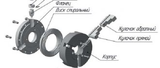
Device
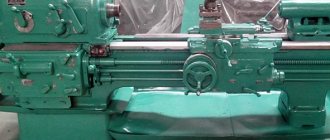
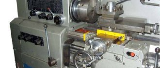
The headstock is attached to the bed, as well as all the main parts of the machine and the tailstock. The main elements in all machines have an identical structure and a general operating principle.
Design elements:
- the fundamental framework where the controls and everything else are placed;
- quill – fastening component;
- one-piece metal body; a control lever that allows you to directly secure the quill and the base of the entire tailstock;
- a flywheel responsible for moving the quill;
- a screw with which the element is clearly secured in relation to the rest of the lathe and all its parts.
Since all the components are identical, the operating principle is not too different.
Principle of operation
The central part of the tailstock is attached to the caliper. Through it, the headstock receives translational motion, since it is equipped with an independent gear drive.
Some types of equipment produce rotational motion. The center of the tailstock itself does not rotate. The specific drive method depends on the modification of the machine, as well as on the tasks that need to be solved.
Node purpose
The main function is to securely secure the workpiece. The unit also supports the second edge of the workpiece and controls stable rotation.
When carrying out the drilling process, the tailstock is connected to the caliper, and a drill of the required size is inserted into the quill chuck.
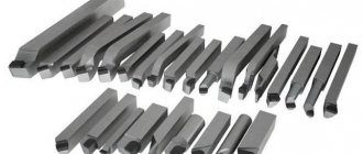
The best wood lathes
A tabletop wood lathe will perform operations such as turning, sanding, grooving and threading. The specificity is the use of hand cutters and shaped devices. To fix the working tool, a hand rest is used, which is installed between the front and rear support.
The VyborExperta.ru project team suggests paying attention to 4 models that will help you process wood with impeccable quality. The equipment is distinguished by good functionality and reliable electric motors, an easy-to-use format
Encore Corvette-74
Stationary wood lathe for the home workshop with a powerful electric motor. With a weight of 77 kg, it has good stability, which has a positive effect on the quality of processing of wooden workpieces. An asynchronous electric motor rotates the spindle at a speed of 500 to 2000 rpm. The distance between centers of 845 mm allows you to process balusters and other large parts. When working with compact workpieces, a faceplate is used.
The variator is responsible for smoothly adjusting the spindle speed. A belt drive helps reduce the load on the electric motor. The manufacturer's assortment includes a copier that can be purchased additionally to increase productivity. For processing parts with a diameter of more than 300 mm, the headstock has a rotating design.
Advantages:
- Adjustable tool holder;
- Reliable protection against spontaneous start-up;
- Base as standard;
- The engine is designed for intensive work;
- Low price.
Flaws:
Insufficient motor power for workpieces larger than 300 mm in diameter.
Einhell 1000/1
The development of German engineers attracted attention with its light weight, powerful engine and four-speed gearbox. The electric motor accelerates the spindle to 2600 rpm. The engine is designed for intensive, long-term operation, which allows the machine to be used in small workshops for the production of carpentry. The double frame ensures good stability of the equipment.
The dimensions of the machine are suitable for workpieces with a diameter of up to 280 mm. A special feature of the tailstock design is a rotating spindle, which simplifies the fixation of the part. A faceplate is provided for working with small workpieces.
Advantages:
- Low price;
- Easy to adjust caliper;
- Stop included;
- Low noise level;
- The maximum length of the workpiece is 1 meter.
Flaws:
It gets hot when working intensively with damp wood.
Skrab 57000
Tabletop machine with a powerful electric motor that spins the spindle at a speed of 5000 rpm. The speed control is stepless, the torque is transmitted using a toothed belt drive. The equipment can be used for processing wood and plastic. It is possible to connect a proprietary flexible shaft.
The maximum length of the workpiece to be processed is 300 mm, diameter – no more than 40 mm. This makes the equipment attractive for model designers, jewelers, and souvenir producers. The machine is attached to the coordinate tables via rubber supports, which reduce vibration. The guide has an ideal surface and is made of an aluminum-based alloy that is resistant to corrosion.
Advantages:
- Protective casing made of durable plastic;
- Low power consumption;
- The speed is regulated automatically;
- Designed for intensive work.
Flaws:
High price for its class.
Record Power DML 305
Desktop model with 370 W motor with stepwise spindle speed adjustment. The electric motor is designed for long-term operation under load, and 6 speeds allow you to solve problems of any complexity. This makes the equipment relevant for professional workshops. The heavy cast iron frame is durable and provides good stability when paired with two massive supports.
The tailstock spindle has a lock with a division scale. This guarantees the accuracy of the settings. Speed shifting is carried out using ergonomic pulleys, which are very easy to access. The model is designed for processing parts with a length of 393 mm, but it is possible to purchase a bed extension for workpieces up to 1 meter.
Advantages:
- Build quality;
- Workpiece diameter up to 305 mm;
- Good equipment;
- Wide range of additional options;
- Stable operation under load.
Flaws:
- Overcharge;
- There is no headstock rotation function.
Headstock device
The main component of the front tank is the spindle. The spindle head is fixed to the left edge of the bed. This is the most important detail of the entire structure.
Various necessary fixtures, tools, and mandrels are fixed in the inner conical hole of the spindle.
How does it work
The movement of the spindle is transmitted from the V-belt pulley. All shafts and the spindle itself are mounted on rolling bearings.
When the machine rotates in a forward direction, large torques are required. This occurs due to the large number of discs that are located on the left side of the friction clutch.
If the gearbox is fixed in the bed frame, then it is connected to the spindle by a belt drive. Such equipment models are called split-drive machines.
What is it for?
The headstock carries out the main movement and transmits torque from the drive motor directly to the workpiece.
If the machine is universal, then the headstock, with the help of structural elements, drives the feed of the support with the cutting tool.
How to sharpen using the method of displacement relative to the axis of centers?
This method allows turning only external conical surfaces on a turning unit. In the process of making a cone using this technique, a misalignment of the center holes occurs. This method does not have the particular precision with which a conical surface can be created.
Important!
This method allows the use of mechanical caliper feed, which makes it possible to use simple types of units. The off-axis method makes it possible to create a long Morse cone.
Adjustment and repair
The adjustment includes the required steps:
- setting the amount of play that forms between the guides at the bed and the base of the tailstock;
- minimum clearances in the quill bearings if it rotates;
- eliminating the center offset relative to the spindle.
How often it is necessary to check and its procedure are indicated in the passport documentation for each machine.
If the need arises, restoration or repair work is carried out. The following parameters are restored:
- precise joining of the frame with the tailstock assembly;
- height of the spindle and quill.
It is also often necessary to restore the accuracy of the hole where the quill is attached.
Taper value
When considering taper, it should be taken into account that this indicator is directly related to the slope. This parameter determines the deviation of a straight line from a vertical or horizontal position. However, a 1:3 taper or a 1:16 taper is significantly different. The definition of slope is characterized by the following features:
- Slope refers to the ratio of the opposite side of a right triangle to the adjacent side. This parameter is also called the tangent of the angle.
- The following formula is used for calculation: i=AC/AB=tga.
This indicator can be calculated in a variety of ways; the most widely used formula is K=D/h. In some cases, the designation is carried out as a percentage, since this variable indicator is used to determine all other parameters.
DIY front and rear quill
The spindle head is a priori the most complex element of all equipment. During manufacturing, it is necessary to take into account that you will need a block of replaceable gears that transmit and change the speed of the rotational movement of the spindle and the torque directly from the gearbox shaft.
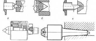
The tailstock is made with a movable or fixed center of rotation. For a movable version of the center, you will need to install a pair of bearings in the quill hole: the front edge with a conical roller, it will be thrust and the rear, radial, bored to a cone.
Installation and fixation of the rear center on the machine is carried out due to the conical hole of the sleeve. The spindle and thrust head are the basis of the design of any lathe.
Therefore, the master must know the principle of their operation, how to make such a part with his own hands and how to adjust it, and, if possible, repair it.
Designation of taper in the drawing
When creating technical documentation, all established standards must be taken into account, otherwise it cannot be used in the future
When considering the taper designation in the drawings, attention should be paid to the following points:
- The diameter of the large base is displayed. The figure under consideration is formed by a body of rotation, which is characterized by a diametrical indicator. In the case of a cone, there may be several of them, and the change in the indicator occurs smoothly, not stepwise. As a rule, such a figure has a larger diameter, as well as an intermediate one if there is a step.
- The diameter of the smaller base is applied. The smaller base is responsible for forming the required angle.
- The length of the cone is calculated. The distance between the smaller and larger bases is an indicator of length.
- Based on the constructed image, the angle is determined. As a rule, appropriate calculations are carried out for this. In the case of determining the size from a printed image, using a special measuring device, the accuracy is significantly reduced. The second method is used when creating a drawing for the production of non-critical parts.
The simplest designation of taper also provides for displaying additional dimensions, for example, reference. In some cases, a taper sign is used, which makes it immediately clear about the difference in diameters.
There are quite a large number of different standards that relate to the designation of taper. The features include the following:
- The angle can be specified in degrees as a fraction or as a percentage. The choice is made depending on the area of application of the drawing. An example is that in the mechanical engineering field the value of a degree is indicated.
- In the mechanical engineering field, the concept of normal taper is included in a special group. It varies within a certain range and can be 30, 45, 60, 75, 90, 120°. Similar indicators are characteristic of most products that are used in the assembly of various mechanisms. At the same time, it is much easier to maintain such values when using turning equipment. However, if necessary, inaccurate angles can be maintained, it all depends on the specific case.
- When drawing the main dimensions, a drawing font is used. It is characterized by quite a large number of features that must be taken into account. Tabular information is used for correct display.
- To begin with, the taper icon is indicated from which the arrow is drawn and the value is displayed. The display features largely depend on what kind of drawing. In some cases, a large number of different sizes are applied, making taper application much more difficult. That is why it is possible to use several different methods for displaying such information.
In the drawing, the indicator in question is indicated in the form of a triangle. This requires a digital value that can be calculated using various formulas.
Read also: Not an integral part of a metal plane
Types of cones
Morse can be manufactured using different technologies, so it is not always possible to replace one tool with another without problems.
Before selecting a suitable fairing, you need to decide what dimensions the Morse cone has that correspond to GOST.
Tools often differ from each other in length, diameter, and angle.
When choosing a fairing, you need to pay attention to the letters and numbers:
- the number opposite the letter “D” means the basic size of the cone socket;
- the number next to “L” is the penetration depth.
These sizes are common to all countries where the metric number system is actively used. Morse fairings created today, as a rule, have adapters that can be changed. This simplifies the work, since the equipment can be combined with different standards.
Capital letters of the Latin alphabet indicate features of the flange section. The proluvium itself can have a length from 2.5 cm to 16 cm.
Today, the highest quality fairings for drilling machines can be considered tools that are produced under the brands “Kennametal” and “Kapto”.
Those who work on the machine know very well that they have good resistance to sudden and significant changes in temperature. The cones of these brands are quite durable and easy to use. They meet all the necessary requirements. Morse codes, which are marked "Capto", are released and distributed throughout the world.
https://youtube.com/watch?v=evWPoMxRr-Q
Today, such instruments are promoted as high-end analogues of HSK. The fairing itself, when projected onto a plane, will have the shape of a triangle. There are indentations on its round edges. But it should be noted that such a tool has a rather high price, since its manufacturing process is very complex. In turn, Kapto are divided into several types, the most popular among which are those designated as “C3” and “C10”.
Initially, such a tool was created so that it could be used for clamping using the collet method.
There is a division into 8 sizes: the smallest of them is designated as “KM0”, and the largest is designated as “KM7”. All other types of cones are also designated by the letters “K”, “M” and a number from 1 to 6
. However, the Russian standard does not recommend using the KM7 Morse fairing; instead, a metric cone No. 80 is used.
Fairings that are designed to both inch and metric standards can be interchanged. They are similar in every way and differ only in the thread of the shank.
Safety precautions
The work will be enjoyable and will not cause injury only if the turner knows and follows safety rules.
Work is performed only in protective clothing. Long hair must be tied back and there should be no hanging jewelry on clothing.
The machine must be reliably grounded. Turning equipment must undergo regular inspections.
Before turning on the machine, you need to check that the workpiece is securely fastened. Under no circumstances should objects be passed through a running machine.
In addition to the written rules, there is one more, unwritten one - do not be afraid of the machine, it is just a tool. If you adhere to this rule and work hard, you can easily become a real professional turner. A little effort, faith in the result and any detail that comes out from under the cutter will become a real creation of a master.
Posted by Sv7, January 11, 2014 in Conversations
Christmas trees made of cardboard
Small tabletop cardboard Christmas trees are an excellent New Year's decor. To strengthen crafts, you can make them by gluing 2-3 layers of cardboard. The work process follows the same principle as with plywood Christmas trees, only instead of a jigsaw or saw we use scissors. We decorate the trees with miniature toys, ribbons, bows, etc.
Wrapping with twine is a simple decoration. You can attach a magnet to the back of the craft.
Christmas trees made of cardboard, covered with burlap. Decorations - beads, lace ribbons, bouquets of artificial flowers. We attach the triangle to a straight branch that will imitate a trunk. We plant a Christmas tree in a pot.
You can cover Christmas trees with fabric of any color
It is important that the decorations contrast with the background
An option for decorating a cardboard Christmas tree is cotton papier mache. It’s simple: we glue layers of cotton wool onto a cardboard base using PVA glue.
Formula for determining taper
You can independently calculate the taper by using various formulas. It is worth considering that in most cases the indicator is indicated in degrees, but it can also be expressed as a percentage - it all depends on the specific case. The calculation algorithm is as follows:
- K=Dd/l=2tgf=2i. This formula is characterized by the fact that the taper is characterized by a double slope. It is based on obtaining the value of the major and minor diameters, as well as the distance between them. In addition, the angle is determined.
- Tgf=D/2L. In this case, the length of the segment that connects the large and small diameters, as well as the indicator of the large diameter, is required.
- F=arctgf. This formula is used to convert the indicator to degrees. Today, in most cases, degrees are used, since they are easier to maintain when directly carrying out constructions. As for percentages, they are often indicated to enable the calculation of one of the diameters. For example, if the ratio is 20% and a smaller diameter is given, then you can quickly calculate the larger one.
As previously noted, the 1:5 taper and other indicators are standardized. For this, GOST 8593-81 is used.
Calculations are not shown in the drawing. As a rule, an additional explanatory note is created for this purpose. It is quite simple to calculate the basic parameters; in some cases, a drawing is constructed, after which the angle value and other indicators are measured.
How to make an internal cone on a lathe.
How to make an internal cone on a lathe. Help an inexperienced turner! You need to make a copy of the pulley, a seat with a cone. The original is lying on the table and I just can’t figure out how to make the same cone. There are no degree meters, and the degree on the machine will probably not be accurate. Are there any tricks to copy a cone?
How to make an internal cone on a lathe.
I would grind the mating part by lapping along the original hole, and then calmly sharpen the new one by fitting along the machined cone
How to make an internal cone on a lathe.
Zuvs, that's right.
How to make an internal cone on a lathe.
Clamp the sample into the chuck with the cone facing outward. Place an indicator on the small longitudinal lever. Unfold the small longitudinal one and move the indicator back and forth along the inner surface of the cone until you adjust the movement of the small longitudinal one parallel to the generatrix of the original cone. And then sharpen a new cone.
How to make an internal cone on a lathe.
https://www.internet-law.ru/gosts/gost/17554/ this is most likely a standard cone with a taper of 1/10
How to make an internal cone on a lathe. Sorry for ignorance, can anyone give a link or photo of what a lever indicator looks like? The cone fits on the crankshaft of the ud-2 engine. How to make an internal cone on a lathe. How to make an internal cone on a lathe. Here. How to make an internal cone on a lathe.
Got it, I'll have to get one of these!
How to make an internal cone on a lathe.
Ilfat (12 April 2012 — 21:12) wrote:
Got it, I'll have to get one of these!
if the machine has a cone ruler, then I advise you to sharpen along it, and not by turning the upper slide. How to make an internal cone on a lathe.
I heard about the cone ruler, but I didn’t see what it looks like, if it’s not difficult for anyone, please show me a photo.
How to make an internal cone on a lathe. Photo from the Internet.
Attached images
How to make an internal cone on a lathe. Thank you!
How to make an internal cone on a lathe.
Ilfat (12 April 2012 — 19:51) wrote:
measure the length of the cone, the smaller and larger diameter. Draw on paper, calculate the angle. How to make an internal cone on a lathe.
there is a formula d large minus d small (diameters) divided by 2 l, that is, the length of the cone multiplied by 2, we look for the resulting value in the table of tangents ..... there you adjust the resulting angle of the tool holder .... you'll figure out there is, of course, another geometric method, well, I think you'll figure it out
How to make an internal cone on a lathe.
MTZ-80, crankshaft cone dimensions UD-2: D=31.8; d=28; l=32. Taper according to the formula: tg2α=(Dd)/2l=(31.8-28)/64=0.0594. Angle α=1.7o
How to make an internal cone on a lathe. MTZ-80, when manufacturing a part, the fit may be a little tighter along a larger diameter, but not at a smaller one - it is checked by the print. How to make an internal cone on a lathe.
Yugra (10 December 2022 — 20:09) wrote:
crankshaft cone dimensions UD-2: D=31.8; d=28; l=32
Where does the information come from? Tyrnet says that 32.5x28.5x40 This is more like the truth, since the Gostovsky 1:10 turns out. How to make an internal cone on a lathe. MTZ-80, IMHO, don’t bother with a ruler or formulas, it won’t work out better than the indicator, especially since the machine probably isn’t of high accuracy. Be sure to take a magnetic stand for the indicator, or just a kit. like this: I don’t know how you work without it. The most necessary thing! Sharpen with low feed, it will probably wear out less. It will be more accurate. You need to measure strictly at the level of the cutter you will be processing. When measuring, first make sure that the cone does not hit the chuck either at the rear edge or at the front. Good luck.
Post edited by Mixxp: 11 December 2022 — 05:06
How to make an internal cone on a lathe.
Kuvaldych, if we bore the pulley to this size, we rest the hub against the cover bolts. At one time I had to do this kind of work quite often.
www.chipmaker.ru