The TV 7M table lathe was produced by the MAGSO small-sized machine tool equipment plant in Rostov-on-Don, founded in 1956. The machines produced by this company are well known in the circles of professional turners and those who have just begun to study turning.
New copies of the screw-cutting lathe of the 7th modified model (TV7M) are still produced to this day because they are in demand throughout the entire post-Soviet space. The main advantages of this model are efficiency and low operating costs.
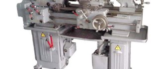
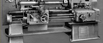
General idea of the TV-7 machine
The TV-7 screw-cutting lathe was produced in Rostov. According to the passport, it was intended to equip school workshops and vocational schools. Many schoolchildren and students learned turning on these machines.
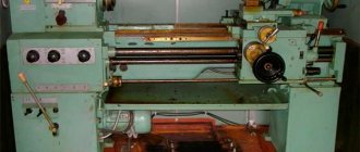
General form.
Speeds are switched by a reduction gearbox with two modes and belt reversal. There are no levers for this purpose.
On TV-7 you can perform the following work:
- cut threads;
- cut off;
- sharpen;
- drill holes;
- trim the ends.
If you have experience and tools, a turner can perform some other types of work.
Purpose of the TV-7M installation and its main components
The TV-7M screw-cutting machine is designed for training novice turners to process metal, plastic and wooden blanks and obtain cylindrical, conical and spherical shapes from them. With this equipment you can:
- make and bore surfaces;
- cut internal and external threads;
- drill;
- cutting and trimming ends.
The base of the TV-7M screw-cutting lathe consists of two stands with a pallet between them. In the front base cabinet, as a rule, a reduction box and an electric drive are installed on a common slide. The rear cabinet contains the electrical equipment of the machine, magnetic starters and fuses.
Specifications
The parameters are largely similar to similar units. There are some differences that have increased the capabilities of this model.
The machine weighs 400 kg, which somewhat reduces vibration during operation. The dimensions of the installation are relatively small: 1050×1200×535 mm.
The passport contains the following technical characteristics:
- the maximum diameter of the blank that can be installed above the frame is 220 mm;
- the maximum diameter of the blank that can be installed above the tool holder is 100 mm;
- distance from the frame to the centers - 120 mm;
- the length of the blank, which can be installed in the centers - 330 mm, in the cartridge - 310 mm;
- the maximum length to which a blank can be machined is 300 mm;
- tool holder height – 16×16 mm;
- hole in the main shaft (diameter) - 18 mm;
- number of stages on direct rotation - 8;
- speed for forward and reverse rotation - 60-1000 per minute;
- the greatest distance through which the tool holder can be moved is 260 mm;
- axial and transverse movement of the tool holder corresponding to one division of the dial - 0.025 mm;
- the maximum possible distance over which the cutting slide moves is 85 mm;
- the number of feed stages of the tool holder along the axis is 8.
Electric motor and reduction box
On TV-7 you can cut metric threads, pitch from 0.8 to 2.5 mm.
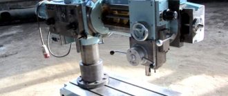
How the bed and headstock of the TV-7 machine are arranged
The main load-bearing element of the equipment of this model, like any other lathe, is the bed on which all structural components are mounted, except for the main electric motor. The frame, made of cast iron using casting technology, is installed on two massive pedestals.
There are four guides on the top of the bed, two of which are prismatic and two are flat. The tailstock moves along the front flat and rear prismatic guides, and the support with a tool holder moves along the rear flat and front prismatic guides.
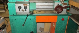
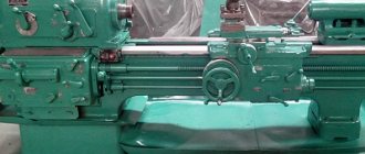
Cartridge TV-7
The headstock, which contains a spindle assembly that imparts rotational movement to the part fixed in it for processing, is located on the left side of the bed. The spindle assembly of the TV-7 school lathe has the following characteristics:
- through hole diameter – 18 mm;
- the number of stages of rotation performed in forward and reverse directions is 8;
- Morse cone category – No. 3;
- rotation of the unit in forward and reverse directions can be performed in the range of 60–1000 rpm.
The workpiece being processed receives rotation from the spindle and is fixed in it using a three-jaw chuck or a faceplate with a driver, which are connected to the spindle itself through a thread on its surface. In the event that it is necessary to process a part in centers, a corresponding conical center is installed in the spindle assembly.
The engine and reduction gearbox are located in the front cabinet of the machine.
To ensure accurate and easy rotation, the spindle assembly is installed in two headstock supports, which are equipped with units with angular contact bearings. During the processing of a part, the machine support must be able to make reverse movements (feeds), for which a special mechanism, also located in the headstock, is responsible. Such movements can be controlled using a special handle.
Reliable and efficient operation of the TV-7 lathe requires regular replacement of used oil with fresh oil. To perform this procedure, the device has a special plug located on the rear side of the headstock. The oil indicator on the front part of the headstock helps to control the level of oil poured into the machine.
Kinematic diagram of TV-7
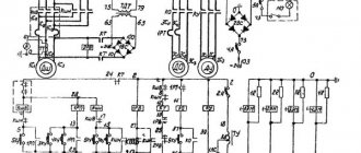
Electrical circuit diagram
Design features
Before starting work, you need to familiarize yourself with the design features. Their knowledge will help to fully realize the capabilities of the unit. You can get a more complete picture of the device from the photo.
Control
The control principle is quite simple. For this there are:
- switches;
- shutdown button;
- rack and pinion button;
- flywheels for moving mechanisms manually.
Controls
In addition, handles are used for control, which perform the following functions:
- tighten the belt;
- turn on the electric motor in reverse;
- start the mechanical feed;
- secure the tailstock;
- move the sled;
- determine the direction of feeding;
- turn on and off the screw and roller;
- select the rotation speed;
- select the thread pitch;
- determine the feed rate;
- fix the incisor holder.
The set of controls ensures reliable control of operations.
Bed and headstock
The bed (guides) rests on the pedestals. All components of the unit, with the exception of the electric motor, are placed on it.
Caliper and headstock
The headstock provides the necessary rotation speed and supports the product. A spindle is mounted into it, and rotation is transmitted from it through a chuck or faceplate.
They are attached to the spindle with threads.
The spindle supports have two bearings. In the headstock there is a reverse feed, which is turned on by a handle.
Caliper, tailstock and feed box
The cutters move on four slides. A cutting head is attached to one of them, which can occupy four positions. It can be rotated and moved in the transverse direction using a handle.
Prolonged operation of the machine leads to the appearance of gaps. Vibration occurs, which affects the accuracy of the work. The operating instructions provide for adjusting the gaps with screws located at the end of the slide.
Sled
The tool holder is attached to the caliper and is pressed out with a handle. The cutters are fastened with fine-threaded bolts that securely hold the working tool.
Tailstock
Moves along the guides, supports the product from the right end, holds tools: drill, cone. A housing with a quill is attached to the base. It can extend, but does not scroll.
The gear mechanism (guitar) transmits movements to the feed box and headstock. The design of the guitar allows for good lubrication and reduced noise.
To control the feed box there is a handle that can be given three positions. One of them provides mechanical movement of the caliper in the longitudinal direction or threading. Play in the box is eliminated by turning the round nuts.
Electrical equipment
The machine is driven by a three-phase asynchronous electric motor with a power of 1.1 kW. To illuminate the workplace there is a lamp operating through a step-down transformer. The unit has an electrical panel, which contains: switches, magnetic starters, transformer, fuses.
Electrical diagram
The electric motor is located in the front cabinet, the panel with electrical equipment is in the rear. On the outside of the shield there is a cam switch.
Design of the TV-7M screw-cutting lathe
The bed of the TV-7M screw-cutting lathe is cast, cast iron, box-shaped with windows. It has two prismatic and two flat guides.
The front prismatic and rear flat guides are used to move the caliper, and the rear prismatic and front flat guides are used to move the tailstock.
Mechanics of screw-cutting lathe TV-7M
Headstock of screw-cutting lathe TV-7m
The headstock serves to secure or support the workpiece and impart rotational motion to it.
The headstock is mounted on the left side of the bed. In the TV-7M model machine, the headstock is also a gearbox, so this term will be used in the future.
Rotation to the input shaft 2 of the gearbox is transmitted from the electric motor by a V-belt transmission through pulley 1.
From input shaft 2 to shaft 3, rotation is transmitted by a gear pair with internal gearing 4 and 5.
Gear 6 and block gear 7 are fixedly fixed on shaft 3.
On shaft 8 there are block gears 9 and 10, which move along the shaft splines using handles 1 and 2 (Fig. 2). Handle 1 has three fixed positions, obtained by turning to the right and left.
Handle 2 has two positions.
The triple block gear 9 has the ability to mesh with gear 6 and block gear 7 and thereby transmit rotation to shaft 8 (three different speeds).
Rotation from shaft 8 to spindle 12 is transmitted through block gears 10 and 11.
Thus, the spindle has 6 speed levels (see Table 5) from 60 to 975 rpm.
The spindle transmits the rotation of the workpiece using a three-jaw chuck or a faceplate with a driver, which are screwed onto its threaded part. When machining parts on centers, a center is inserted into the spindle.
The feed movement of the caliper is borrowed from the spindle. Shaft 13 receives rotation through gears 14-15. From shaft 13 the movement is transmitted to the guitar gear - 17.
A device is mounted in the headstock that allows you to change the direction of movement of the caliper - to reverse the feed. Rotation is reversed by moving gear 15 to the left and right extreme positions using handle 3.
In the left extreme position, gear 15 will receive direct rotation directly from the gear block 14 located on the spindle.
In the right extreme position, gear 15 will receive reverse rotation through idler gear 16, which is in constant engagement with the second stage of gear block 14.
On the front side of the headstock housing there is an oil indicator 18. On the reverse side there is a plug 19 for draining the oil.
Guitar screw-cutting lathe TV-7M
The guitar (Fig. 5) serves to transmit rotation from the headstock spindle to the feed box.
The guitar assembly includes a bracket 6, two axles 5 pressed into it, on which the gears rotate freely.
Rotation from gear 1 sitting on the output shaft of the headstock is transmitted to the replacement gear, and then through gears 2-3-4 it is transmitted to the input shaft of the feedbox.
Feed box for screw-cutting lathe TV-7M
The movement from the spindle of the headstock of the machine through the transmission mechanism (guitar) is transmitted to shaft 1 of the feed box (Fig. 6).
When turning handle 4 (Fig. 2), which has three fixed positions, block gear 6 moves along the splines of shaft 5 and its rims alternately engage with gears 2, 3, 4, stationary on shaft 1 (Fig. 6) .
This makes it possible, together with the replacement gears of the guitar, to obtain a metric thread with a pitch of 0.8; 1.0; 1.25; 1.5; 2.0; 2.5 mm and longitudinal mechanical feed of the caliper 0.1; 0.12; 0.15; 0.16; 0.18; 0.20; 0.24; 0.32 mm/rev.
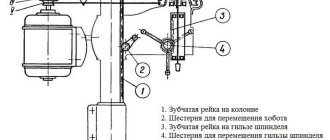
Apron
Using the apron (Fig. 7), you can perform mechanical longitudinal feed of the caliper from the lead roller and from the lead screw, as well as manual longitudinal feed.
Manual feed is carried out by rotating the flywheel 1, mounted on the pinion shaft 4, which engages with gear 3, sitting on the shaft of rack and pinion gear 2.
The rack and pinion meshes with a rack that is rigidly attached to the frame. Mechanical feed from the running roller 10 is carried out by a worm 5 connected to the roller by a sliding key. The worm causes the worm gear 11 to rotate and then through the cam clutch and gears 13, 3 the rotation is transmitted to the rack and pinion gear. To turn on the mechanical feed, you need to turn handle 6 towards yourself, and the claw clutch is turned on.
Support for screw-cutting lathe TV-7M
The support (Fig. is designed to secure and move the cutter. The support has four slides.
Slide 1 moves in the longitudinal direction along the frame guides.
Slide 2 moves along the transverse guides of slide 1 and serves to move the cutter transversely.
Slide 4, carrying a four-position cutting head, has only longitudinal movement along the guides of slide 3, which has the ability to rotate 40° from the average position in one direction or another.
Transverse movement of slide 2 along the guides of lower slide 1 is carried out by screw 6 and nut 5.
Screw 6 is rotated by hand using handle 12.
On top, slide 2 has a recess into which the protrusion of the rotating part of the upper support fits; To secure the rotating part, there are 2 bolts, the heads of which fit into the T-shaped groove of slide 2.
The upper slide 4 of the support can be moved along the guides manually using a handle 7, which rotates the screw 8. The guides of the frame, slides and wedges wear out so much from prolonged operation that a gap may appear between them.
Tailstock of screw-cutting lathe TV-7M
The tailstock serves to support the second end of the workpiece. Housing 1 is located on base 2, which moves along the guides of the machine bed.
The quill 3 is swept longitudinally in the body.
The quill has a conical hole (Morse taper 2) into which a stop center or other tool is inserted; drills, reamers, drill chuck, etc. The quill is moved by handwheel 4, which rotates screw 5.
Exploitation
The operating instructions draw attention, first of all, to the need to comply with safety measures. Basic Rules:
- Install the equipment on a rigid foundation; check the level of the installation with a level. The accuracy of the work largely depends on correct installation;
- reliably ground the machine in accordance with the requirements;
- use a wooden lattice as a stand;
- fasten the workpieces securely;
- use cutters with proper sharpening;
- secure the part in the chuck so that the cams grip it to the maximum possible extent;
Cartridge, the guides are clearly visible in the photo
- do not screw the cartridge by sudden braking;
- fasten in the chuck without emphasis on the center of the rear centered parts no more than two diameters long. For longer lengths, use the center;
- Having installed the parts in the centers, check the fixation of the tailstock;
- remove shavings in a timely manner using a crochet hook.
Machine care
For reliable and durable operation, the following rules must be followed:
- Before making switches, the machine must be completely stopped. If the gear pair does not engage or the gear clutch does not engage, turn the chuck by hand until the gears or clutch engage. Switching when the machine is not completely stopped leads to impacts, which causes rapid wear and breakage of gears and couplings.
- When installing the cartridge, clean the threads. Contaminated threads lead to chuck jamming and spindle breakage.
- Caliper seals require maintenance. Chips gradually accumulate in them, which damages the guides.
- Make sure that after the caliper there is no dirty mark on the guides. If a dirty mark becomes noticeable, it is washed off and the guides are lubricated with clean oil.
- The machine should not be overloaded. Overload causes increased noise, belts slip, bearings and the electric motor overheat.
- If the part is machined in the centers, the quill is extended to the smallest amount: the fastening will be secured more firmly, and the quill will last longer.
You can watch a video about working on the TV-7 lathe
Lubrication
Timely lubrication guarantees trouble-free, long-lasting operation . Rubbing parts, screws, shafts, gears, bearings are subject to lubrication. The following components are lubricated:
- Headstock through the top cover. An oil level indicator is used to control the level.
- Reducing box through a plug. An oil level indicator is used to control the level.
- Feed box through the tray at the top. From there it is fed through wicks to the rubbing surfaces and gears. There should always be some oil in the trough. The accumulated oil is drained through the plug from below.
- Guitar: Grease is used to lubricate the gears and bushing.
- On the bed, all mechanisms, bearings, and guides are lubricated manually before starting work.
- Everything in the apron is lubricated through the hole at the bottom of the caliper. Lubrication is carried out every time before starting work.
- Everything in the caliper is lubricated by hand before work.
- Tailstock. Lubricate the quill and the screw support before work.
Lathe lubrication system
Timely lubrication of all working units of turning equipment is the key to long-term and trouble-free operation of the machine. In the lubrication system of the TV-7M training and production unit, industrial oil I-20A and Zh grade grease should be used.
The headstock bearings and gears are automatically lubricated by spraying oil from a special oil bath located in the unit housing. Oily liquid is poured into the bath when the top cover is removed. Lubricant control in the headstock is carried out using a special level indicator eye. The level should not be lower than the middle of the eye. The oil change is carried out for the first time after 10 days of operation, subsequent ones - every 40 days.
The feed box has a special place for filling with oil at the top of the unit. From this place, oil reaches the surfaces of rubbing parts and gears through a wick feed. When turning workpieces, there should always be some oil in this tray.
The accumulated grease in the lower part is drained using a drain plug. As a rule, you need to add lubricating fluid to the trough once every 5 days. The waste must be drained from the assembly body for the first time after 10 days, and subsequent times every 20 days.
The apron, caliper and tailstock mechanisms are lubricated by hand at least once per work shift. Lubrication of bearings, guides, as well as rollers and screws on the frame must be done manually at least once a month. The guitar must be lubricated by hand once a month of use.
How to choose the right used machine
TV-7 has been discontinued, so you can only buy a used unit. The search for sellers is most often carried out on the Internet. In particular, on the free classifieds site Avito. In addition, there are many other sites where you can also purchase a machine, for example, the machine tool exchange. Prices range from 25 thousand rubles to 85 thousand rubles. It is clear that the price depends on the safety and technical condition of the equipment.
First of all, you need to contact the seller and find out the condition of the unit in a conversation. Once a purchase decision has been made, the next important step is to inspect and test the machine. The inspection begins with the most important part - the frame guides, checking their wear, which should be minimal. However, it is possible to find a used machine with virtually no wear and tear, it all depends on the conditions under which and how much it was used.
Next, the operation of the following components is inspected and checked:
- movement of the caliper, play, the ability to adjust it;
- spindle rotation: easy, silent, without vibration indicates good condition of the bearings;
- condition of the jaw chuck: clamping reliability, easy, no jamming, movement of the jaws;
- operation of the cutting head: rotation, fixation; reliability of fastening of cutters;
- condition of the tailstock: movement along the guides, fixation, quill;
- operation of handles, condition of adjusting bolts and nuts, threaded connections.
It is very good if it is possible to test the installation in different modes. Such a test will give the most truthful picture of the actual condition of the machine.
Reviews
The overall assessment of the craftsmen using the TV-7 machine is positive; all parameters stated in the technical specifications are supported. With proper care - timely lubrication, adjustment - the machine provides high precision work.
As a positive side, users note the possibility of purchasing the unit at an affordable price. The simplicity of control, reliability, and ease of performing all the work operations stated in the passport are also noted.
Owners of the unit note high reliability and ease of operation. The installation is used at home, at private service stations, in small workshops, and by farmers. They carry out repairs of small parts, make bolts, nuts, and, if possible, turn some products.
Users who have been using TV-7 for many years note that no significant breakdowns have occurred during this time. All that is required from the turner is to keep the installation, especially the guides, clean, and timely lubrication