Electronics for a spotter from what is at hand
An acquaintance came, brought two LATRs and asked if it was possible to make a spotter out of them? Usually, when hearing a similar question, what comes to mind is an anecdote about how one neighbor asks another if he knows how to play the violin and in response he hears “I don’t know, I haven’t tried” - so I have the same answer - I don’t know , probably “yes”, but what is a “spotter”?
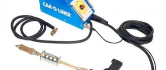
In general, while the tea was boiling and brewing, I listened to a short lecture about how you shouldn’t do what you shouldn’t do, that you need to be closer to the people and then people will be drawn to me, and also briefly plunged into the history of car repair shops, illustrated with delicious tales from the life of “chiropper” and “tinsmith”. Then I realized that a spotter is a small “welder” that works on the principle of a spot welding machine. It is used to “grab” metal washers and other small fasteners to a dented car body, with the help of which the deformed sheet is then straightened. True, they also need a “reverse hammer”, but they say that this is no longer my concern - only the electronic part of the circuit is required from me.
Having looked at spotter circuits online, it became clear that we needed a one-shot device that would “open” the triac for a short time and supply mains voltage to the power transformer. The secondary winding of the transformer should produce a voltage of 5-7 V with a current sufficient to “grab” the washers.
To generate a triac control pulse, different methods are used - from simple capacitor discharge to the use of microcontrollers with synchronization to the phases of the mains voltage. We are interested in the simpler circuit - let it be “with a capacitor”.
Searches “in the nightstand” showed that, in addition to passive elements, there are suitable triacs and thyristors, as well as many other “small things” - transistors and relays for different operating voltages ( Fig. 1 ). It’s a pity that there are no optocouplers, but you can try to assemble a capacitor discharge pulse converter into a short “rectangle”, including a relay, which will open and close the triac with its closing contact.
Fig.1
Also, while searching for parts, we found several power supplies with DC output voltages from 5 to 15 V - we chose an industrial one from “Soviet” times called BP-A1 9V/0.2A ( Fig. 2 ). When loaded with a 100 Ohm resistor, the power supply produces a voltage of about 12 V (it turned out that it had already been converted).
Fig.2
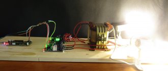
We select triacs TS132-40-10, a 12-volt relay from the available electronic “garbage”, take several KT315 transistors, resistors, capacitors and begin to prototype and test the circuit (in Fig. 3 one of the setup stages).
Fig.3
The result is shown in Figure 4 . Everything is quite simple - when you press the S1 button, capacitor C1 begins to charge and a positive voltage equal to the supply voltage appears at its right terminal. This voltage, having passed through the current-limiting resistor R2, is supplied to the base of the transistor VT1, it opens and voltage is supplied to the winding of relay K1, and as a result, the contacts of relay K1.1 close, opening triac T1.
Fig.4
As capacitor C1 charges, the voltage at its right terminal gradually decreases and when it reaches a level less than the opening voltage of the transistor, the transistor will close, the relay winding will be de-energized, the open contact K1.1 will stop supplying voltage to the control electrode of the triac and it will close at the end of the current half-wave of the mains voltage . Diodes VD1 and VD2 are installed to limit the pulses that occur when the S1 button is released and when the relay winding K1 is de-energized.
In principle, everything works like this, but when monitoring the time of the open state of the triac, it turned out that it “walks” quite a lot. It would seem that even taking into account possible changes in all on-off delays in electronic and mechanical circuits, it should be no more than 20 ms, but in fact it turned out to be many times more and plus this, the pulse lasts 20-40 ms longer, and then for all 100 ms.
After a little experimentation, it turned out that this change in pulse width is mainly due to a change in the supply voltage level of the circuit and the operation of transistor VT1. The first was “cured” by mounting a simple parametric stabilizer inside the power supply unit, consisting of a resistor, a zener diode and a power transistor ( Fig. 5 ). And the cascade on transistor VT1 was replaced by a Schmitt trigger on 2 transistors and the installation of an additional emitter follower. The scheme took the form shown in Figure 6 .
Fig.5
Fig.6
The principle of operation remains the same, the ability to discretely change the pulse duration using switches S3 and S4 has been added. The Schmitt trigger is assembled on VT1 and VT2 [1], its “threshold” can be changed within small limits by changing the resistance of resistors R11 or R12.
When prototyping and testing the operation of the electronic part of the spotter, several diagrams were taken, from which time intervals and the resulting delays of edges can be assessed. At that time, the circuit had a timing capacitor with a capacity of 1 μF and resistors R7 and R8 had a resistance of 120 kOhm and 180 kOhm, respectively. Figure 7 above shows the state on the relay winding, below - the voltage at the contacts when switching a resistor connected to +14.5 V (the file for viewing by the SpectraPLUS program is in the archived appendix to the text, the voltages were taken through resistor dividers with random division coefficients, therefore "Volts" scale is not true). The duration of all relay power pulses was approximately 253...254 ms, the contact switching time was 267...268 ms. The “extension” is associated with an increase in the shutdown time - this can be seen in Figures 8 and 9 when comparing the difference that occurs when the contacts are closed and opened (5.3 ms vs. 20 ms).
Fig.7
Fig.8
Fig.9
To check the temporal stability of pulse formation, four sequential switchings were carried out with control of the voltage in the load (file in the same application). The generalized Figure 10 shows that all pulses in the load are quite close in duration - about 275...283 ms and depend on where the half-wave of the mains voltage occurs at the moment of switching on. Those. the maximum theoretical instability does not exceed the time of one half-wave of the mains voltage - 10 ms.
Fig.10
When setting R7 = 1 kOhm and R8 = 10 kOhm with C1 = 1 μF, it was possible to obtain a duration of one pulse of less than one half-cycle of the mains voltage. At 2 µF - from 1 to 2 periods, at 8 µF - from 3 to 4 (file in attachment).
The final version of the spotter was equipped with parts with the ratings indicated in Figure 6 . What happened on the secondary winding of the power transformer is shown in Figure 11 . The duration of the shortest pulse (the first in the figure) is about 50...60 ms, the second - 140...150 ms, the third - 300...310 ms, the fourth - 390...400 ms (with a timing capacitor capacity of 4 μF, 8 μF, 12 μF and 16 µF).
Fig.11
After checking the electronics, it's time to tackle the hardware.
A 9-amp LATR was used as a power transformer (right in Fig. 12 ). Its winding is made of wire with a diameter of about 1.5 mm ( Fig. 13 ) and the magnetic core has an internal diameter sufficient to wind 7 turns of 3 parallel folded aluminum busbars with a total cross-section of about 75-80 sq. mm.
Fig.12
Fig.13
We disassemble the LATR carefully; just in case, we “fix” the entire structure in the photo and “copy” the conclusions ( Fig. 14 ). It’s good that the wire is thick - it’s convenient to count the turns.
Fig.14
After disassembly, carefully inspect the winding, clean it of dust, debris and graphite residues using a hard-bristled paint brush and wipe with a soft cloth slightly moistened with alcohol.
We solder a five-amp glass fuse to terminal “A”, connect the tester to the “middle” terminal of coil “G” and apply a voltage of 230 V to the fuse and the “unnamed” terminal. The tester shows a voltage of about 110 V. Nothing buzzes or gets hot - we can assume that the transformer is normal.
Then we wrap the primary winding with fluoroplastic tape with such an overlap that we get at least two or three layers ( Fig. 15 ). After this, we wind a test secondary winding of several turns with a flexible wire in insulation. Having applied power and measured the voltage on this winding, we determine the required number of turns to obtain 6...7 V. In our case, it turned out that when 230 V is applied to the “E” and “unnamed” terminals, 7 V is obtained at the output with 7 turns. When power is applied to “A” and “unnamed”, we get 6.3 V.
Fig.15
For the secondary winding, “very used” aluminum busbars were used - they were removed from an old welding transformer and in some places had no insulation at all. In order to prevent the turns from shorting with each other, the tires had to be wrapped with sickle tape ( Fig. 16 ). The winding was carried out so that two or three layers of coating were obtained.
Fig.16
After winding the transformer and checking the functionality of the circuit on the desktop, all the parts of the spotter were installed in a suitable-sized housing (it looks like it was also from some kind of LATR - Fig. 17 ).
Fig.17
The terminals of the secondary winding of the transformer are clamped with M6-M8 bolts and nuts and are brought out to the front panel of the housing. Power wires leading to the car body and the “reverse hammer” are attached to these bolts on the other side of the front panel. The appearance at the home inspection stage is shown in Figure 18 . At the top left are the mains voltage indicator La1 and the mains switch S1, and on the right is the pulse voltage switch S5. It switches the connection to the network of either terminal “A” or terminal “E” of the transformer.
Fig.18
At the bottom there is a connector for the S2 button and the secondary winding leads. The pulse duration switches are installed at the very bottom of the case, under the hinged lid (Fig. 19 ).
Fig.19
All other elements of the circuit are fixed to the bottom of the case and the front panel ( Fig. 20 , Fig. 21 , Fig. 22 ). It doesn’t look very neat, but the main goal here was to reduce the length of the conductors in order to reduce the influence of electromagnetic pulses on the electronic part of the circuit.
Fig.20
Fig.21
Fig.22
The printed circuit board was not wired - all the transistors and their “piping” were soldered to a breadboard made of fiberglass, with foil cut into squares (visible in Fig. 22 ).
Power switch S1 is JS608A, allowing switching of 10 A currents (“paired” terminals are paralleled). There was no second such switch, so S5 was installed as TP1-2, its terminals are also paralleled (if you use it with the mains power off, it can pass quite large currents through itself). Pulse duration switches S3 and S4 - TP1-2.
Button S2 – KM1-1. The connector for connecting the button wires is COM (DB-9).
Indicator La1 - TN-0.2 in the corresponding installation fittings.
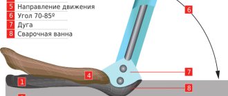
Figures 23 , 24 , 25 show photographs taken when checking the functionality of the spotter - a furniture corner measuring 20x20x2 mm was spot welded to a 0.8 mm thick tin plate (mounting panel from a computer case). The different sizes of the “spots” in Fig. 23 and Fig. 24 are for different “cooking” voltages (6 V and 7 V). In both cases, the furniture corner is welded tightly.
Fig.23
Fig.24
Fig.25
Fig . 26 shows the back side of the plate and it can be seen that it heats up through and through, the paint burns and flies off.
Fig.26
After I gave the spotter to a friend, he called about a week later and said that he had made a reverse “hammer”, connected it and checked the operation of the entire device - everything is fine, everything works. It turned out that long-duration pulses are not needed in operation (i.e. elements S4, C3, C4, R4 can be omitted), but there is a need to connect the transformer to the network “directly”. As far as I understand, this is so that the surface of the dented metal can be heated using carbon electrodes. It is not difficult to supply power “directly” - they installed a switch that allows you to close the “power” terminals of the triac. The insufficiently large total cross-section of the cores in the secondary winding is a little confusing (according to calculations, more is needed), but since more than two weeks have passed, and the owner of the device was warned about the “weakness of the winding” and did not call, then nothing terrible happened.
During experiments with the circuit, a version of a triac assembled from two T122-20-5-4 thyristors was tested (they can be seen in Figure 1 in the background). The connection circuit is shown in Fig. 27 [2], diodes VD3 and VD4 are 1N4007.
Fig.27
Literature:
- Goroshkov B.I., “Radio-electronic devices”, Moscow, “Radio and Communications”, 1984.
- Mass radio library, Ya.S. Kublanovsky, “Thyristor devices”, M., “Radio and Communications”, 1987, issue 1104.
Andrey Goltsov, Iskitim.
List of radioelements
| Designation | Type | Denomination | Quantity | Note | Shop | My notepad |
| To picture No. 6 | ||||||
| VT1, VT2, VT3 | Bipolar transistor | KT315B | 3 | Search in the Otron store | To notepad | |
| T1 | Thyristor & Triac | TS132-40-12 | 1 | Search in the Otron store | To notepad | |
| VD1, VD2 | Diode | KD521B | 2 | Search in the Otron store | To notepad | |
| R1 | Resistor | 1 kOhm | 1 | 0.5 W | Search in the Otron store | To notepad |
| R2 | Resistor | 330 kOhm | 1 | 0.5 W | Search in the Otron store | To notepad |
| R3, R4 | Resistor | 15 kOhm | 2 | 0.5 W | Search in the Otron store | To notepad |
| R5 | Resistor | 300 Ohm | 1 | 2 W | Search in the Otron store | To notepad |
| R6 | Resistor | 39 Ohm | 1 | 2 W | Search in the Otron store | To notepad |
| R7 | Resistor | 12 kOhm | 1 | 0.5 W | Search in the Otron store | To notepad |
| R8 | Resistor | 18 kOhm | 1 | 0.5 W | Search in the Otron store | To notepad |
| R9 | Resistor | 1.5 kOhm | 1 | 0.5 W | Search in the Otron store | To notepad |
| R10 | Resistor | 2 kOhm | 1 | 2 W | Search in the Otron store | To notepad |
| R11 | Resistor | 1.2 kOhm | 1 | 0.5 W | Search in the Otron store | To notepad |
| R12 | Resistor | 100 Ohm | 1 | 0.5 W | Search in the Otron store | To notepad |
| C1, C2, C3, C4 | Capacitor | 4 µF/160V | 4 | Search in the Otron store | To notepad | |
| C5 | Capacitor | 10 nF/630V | 1 | Search in the Otron store | To notepad | |
| C6 | Electrolytic capacitor | 100uF/25V | 1 | Search in the Otron store | To notepad | |
| S1 | Switch | JS608A | 1 | Search in the Otron store | To notepad | |
| S3, S4, S5 | Switch | TP1-2 | 3 | Search in the Otron store | To notepad | |
| S2 | Switch | KM1-1 | 1 | Search in the Otron store | To notepad | |
| La1 | Indicator | TN-0.2 | 1 | Search in the Otron store | To notepad | |
| Add all | ||||||
Attached files:
- Spotter work files.rar (2865 KB)
Tags:
- Welding
The purpose of the spotter and its features
A homemade spotter is used for car body work. This is done when, for some reason, to level the surface of the part . You can locally heat the metal using the specified tool if there is minor damage to the body area. It is important to figure out how to make a spotter with your own hands in order to get a high-quality and functional product.
The welding process looks like this. Fasteners are fixed in place of the damaged metal. A device is connected to it and the dents are pulled out using auxiliary devices or with your own hands. The body repair tool makes it possible to quickly and efficiently restore a car without painting the damaged area. The good thing about a spotter is that during its operation it is possible to keep the functioning of every part under control. This is due to the fact that the likelihood of overheating and breaking the wires is quite high.
Unit design properties
The device consists of components such as a box, a gun, a cable, and an electrode.
The box contains the entire apparatus system that is necessary for welding . In order to carry out body work clearly and quickly, you must adhere to the order and technology of the process.
If the surface has undergone deformation, it must be cleaned of any coating. It could be rust, paint or varnish. This stage is very important, since the quality of the metal connection directly affects the outcome of the entire process. Contacts are attached to the surface that has been adjusted. A fastener is welded onto the cleaned area of the damaged area, to which the device in question is connected.
Read also: How to chop branches without a chopper
Following this, the device is grabbed with a gun, after which the dent is pulled out. For leveling, they resort to using a hammer, hydraulic cylinders and other devices. Pay attention to the thickness of the metal. Here you should understand what equipment will make it possible to straighten the machine so as not to cause harm to it. The back hammer is not used in combination with aluminum. In addition, not every unit can cope with a galvanized body. When the body straightening is completed, the welded part is twisted. The contact area is cleaned with a grinding machine.
Examination
Before use, you must first check the equipment for operational safety. To do this, a preventive examination is carried out:
- clean all elements;
- check the correct insulation of the wires;
- clean the deformed surface;
- inspect the reliability of fastening of all parts;
- ground the device.
Only after carrying out the above steps, you can start using the unit.
Attention! If you do not follow safety rules, you may receive a severe electric shock.
DIY manufacturing algorithm
To make the unit yourself, you need some skills and an understanding of the basics of working with such equipment. You can make a spotter from a welding machine yourself in accordance with the drawings. To do this, you need to carefully study the design features of the device. You can use available parts.
It is not always advisable to purchase a factory-made device. A quality unit can cost a pretty penny. It is necessary to consider the configuration of the device and its drawings.
Equipment from inverter apparatus
Most often, an inverter-based unit is made using homemade material. The main components of the device are a thyristor relay and a welding inverter. To assemble the device you will need:
- thyristor with an indicator of 200 Volts;
- transformer to step down 122 volts to control the relay using a button;
- relay with a power of 30 amperes;
- diode bridge;
- button for control and monitoring;
- contact group 220 volts.
The transformer is connected using a diode bridge. The relay thyristor is connected to it. The transformer powers the control branch of the circuit. Before making a spotter with your own hands, you need to ensure safe working conditions. For this purpose, rubber mats are placed under your feet and standard safety regulations are followed.
Main assembly steps
To make a homemade unit, a Nordic welding machine is ideal. It is necessary to be able to change the configuration of the device so that the DC spotter outputs 1500 amperes, at a minimum. Assembly is carried out according to the following rules:
- Remove the secondary layer from the apparatus. Sometimes there are several of them.
- Before installation, determine the number of turns per 1 Volt. For this purpose, the primary winding is wrapped in copper wire. Then the Volt indicator is measured.
- The resulting figure is divided by the number of turns. The result will indicate the number of turns per volt.
- The secondary layer that has been removed is used to produce a tire. It is advisable not to allow this parameter to fall below 160 square mm.
- The voltage should be 6 volts. If the cross-section is smaller, you can divide the tire into several parts. They are secured with insulating tape.
The number of fragments depends on the initial indicators. Let's say if the parameter is 40 sq. mm., the tire breaks into 4 parts. You need to take two tires wrapped with electrical tape or adhesive tape for painting work. Isolation must be consistent. First there is a layer of insulating tape, then adhesive tape, and insulating tape is wound on top. Rivets can be installed on open areas.
The resulting busbars are moved to the transformer. This process is not easy and requires certain skills. A hammer and an additional assistant are required. Thanks to this, the tire will fit better and will not suffer any damage. If the power indicator is normal, then the device can be considered ready. If not, you will have to conduct a series of experiments by connecting wires to the primary winding.
Scheme
The unit has a not very complex circuit, the main unit of which is welding equipment with a primary winding powered from the mains. When making a spotter, you can use the following energy distribution schemes.
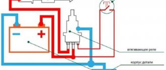
Principal electrical
It consists of power supply equipment, where the voltage on the secondary winding is 12V. To control the current, it is equipped with an additional winding.
Simple
The simplest circuit eliminates the use of a thyristor switch. The supply of current occurs as a result of a short circuit that occurs in the primary winding circuit. Among the disadvantages is the supply of high voltage to the pistol handle, which is unsafe.
Thyristor
Phase shift is used to adjust the current. Suitable for adjusting voltage in alternating electrical circuits. In order for a single-phase network to operate, 2 thyristors are required, which are connected opposite each other. The tuning should be symmetrical and synchronous. Units created using this type of thyristors (semiconductors) have a rigid static characteristic.
Final assembly
To break the contacts of the primary network, the jumpers must be connected correctly. To do this, cables and switches are inserted into the control unit at the start button. Then they are brought to the body base. If necessary, coolers are used.
Finally, it is advisable to use shellac to impregnate the resulting unit.
Transformer production stages
Assembling the transformer is a mandatory step in the manufacture of a spotter from a welding machine. This kind of work is the most difficult. Winding requires a lot of time, but this step is not necessary. The winding is carried out on a ring iron. The wire for the secondary winding should be made of aluminum or copper. High-quality insulation should be laid between the coils. Transformer paper in several layers is suitable for this. For maximum reliability, it is impregnated with paraffin.
The pistol is made from a semi-automatic machine . It will require some additions to secure the tool to the drawing device. To make pliers, a simple 20 by 20 mm pipe will do. The power wires connecting the transformer and the gun must have an identical cross-section. Alternatively, they must exceed the tire cross-section. Do not use wires that are too long. Their maximum size should be 2.5 m. The operating cable connecting the transformer and the gun should be made on the basis of a thermally insulated commutation cable. Each time it is heated, this layer will shrink.
Where can I buy
You can purchase a ready-made timer or time relay either in a specialized store or online in an online store. In the second case, the budget option for purchasing products on the Aliexpress website deserves special attention. For some devices there is an option for shipment from a warehouse in the Russian Federation; they can be received as quickly as possible; to do this, when ordering, select “Delivery from the Russian Federation”:
| Digital time delay relay module | Timer switch | Electronic time relay GEYA with delay |
| Universal time relay with a range from 1 to 60 minutes | Digital programmable timer TM618H | Digital time relay with display |
How does the 555 chip work?
Before moving on to the example of a relay device, let's consider the structure of the microcircuit. All further descriptions will be made for the NE555 manufactured by Texas Instruments.
As can be seen from the figure, the basis is an RS flip-flop with an inverse output, controlled by outputs from comparators. The positive input of the upper comparator is called THRESHOLD, the negative input of the lower one is called TRIGGER. Other comparator inputs are connected to a supply voltage divider consisting of three 5 kOhm resistors.
As you most likely know, an RS flip-flop can be in a steady state (it has a memory effect of 1 bit) either in a logical “0” or in a logical “1”. How it works:
- The arrival of a positive pulse at input R (RESET) sets the output to logical “1” (namely “1”, not “0”, since the trigger is inverse - this is indicated by the circle at the trigger output);
- The arrival of a positive pulse at input S (SET) sets the output to logical “0”.
Three 5 kOhm resistors divide the supply voltage by 3, which leads to the fact that the reference voltage of the upper comparator (the “–” input of the comparator, also known as the CONTROL VOLTAGE input of the microcircuit) is 2/3 Vcc. The reference voltage of the lower one is 1/3 Vcc.
With this in mind, it is possible to create tables of states of the microcircuit regarding the TRIGGER, THRESHOLD inputs and OUT output. Note that the OUT output is the inverted signal from the RS flip-flop.
| THRESHOLD < 2/3 Vcc | THRESHOLD > 2/3 Vcc | |
| TRIGGER < 1/3 Vcc | OUT = log "1" | undefined state OUT |
| TRIGGER > 1/3 Vcc | OUT remains unchanged | OUT = log "0" |
Using this functionality of the microcircuit, you can easily make various signal generators with a generation frequency independent of the supply voltage.
In our case, to create a time relay, the following trick is used: the TRIGGER and THRESHOLD inputs are combined together and a signal is supplied to them from the RC chain. The state table in this case will look like this:
| OUT | |
| THRESHOLD, TRIGGER < 1/3 Vcc | OUT = log "1" |
| 1/3 Vcc < THRESHOLD, TRIGGER < 2/3 Vcc | OUT remains unchanged |
| THRESHOLD, TRIGGER > 2/3 Vcc | OUT = log "0" |
The NE555 connection diagram for this case is as follows:
After power is applied, the capacitor begins to charge, which leads to a gradual increase in the voltage across the capacitor from 0V onwards. In turn, the voltage at the TRIGGER and THRESHOLD inputs will, on the contrary, decrease, starting from Vcc+. As can be seen from the state table, there is a logical “0” at the OUT output after Vcc+ is applied, and the OUT output switches to a logical “1” when the voltage at the indicated TRIGGER and THRESHOLD inputs drops below 1/3 Vcc.
The important fact is that the relay delay time, that is, the time interval between applying power and charging the capacitor until the OUT output switches to logical “1”, can be calculated using a very simple formula:
T = 1.1 * R * C And as you can see, this time does not depend on supply voltage.
Consequently, when designing a time relay circuit, you don’t have to worry about power stability, which significantly simplifies the circuit design. Next, we present a drawing of a variant of the microcircuit in a DIP package and show the location of the chip pins:
It is also worth mentioning that in addition to the 555 series, the 556 series in a package with 14 pins. The 556 series contains two 555 timers.