The 2A554 radial drilling machine, produced by the Odessa Radial Drilling Machines Plant, was created for processing parts of significant size and weight. Such workpieces are quite difficult to process using a conventional drilling machine, since the operator has to expend serious effort to move them along the surface of the work table. The design features of the machine model 2A554 allow, by manipulating only the working part of the equipment, to drill almost any part of the part, as well as to effectively perform a number of other technological operations.
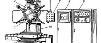
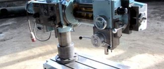
Machine appearance
According to the technical data sheet, the equipment of this model is used for:
- drilling holes of various diameters;
- opening holes;
- countersinking;
- cutting in internal thread holes;
- end processing (trimming).
It is possible to process large-sized workpieces on such equipment efficiently and without significant labor costs on the part of the operator due to the fact that its spindle head has several degrees of freedom.
The main part of the controls of the radial drilling machine model 2A554, in contrast to drilling devices of a standard design, is concentrated in the working head. The latter is located on a special traverse (sleeve), rotating together with the column on which it is mounted. The traverse, in addition to rotation, can move along the column along a vertical axis, and the drilling head can move along the sleeve in a horizontal plane.
Machine controls
Such technical capabilities significantly expand the functionality of the radial drilling machine model 2A554. The control system with which it is equipped makes it quite easy to automate the technological operations performed on it.
Technical characteristics and passport of the radial drilling machine 2A554
The 2A554 radial drilling machine, produced by the Odessa Radial Drilling Machines Plant, was created for processing parts of significant size and weight. Such workpieces are quite difficult to process using a conventional drilling machine, since the operator has to expend serious effort to move them along the surface of the work table. The design features of the machine model 2A554 allow, by manipulating only the working part of the equipment, to drill almost any part of the part, as well as to effectively perform a number of other technological operations.
Machine appearance
According to the technical data sheet, the equipment of this model is used for:
- drilling holes of various diameters;
- opening holes;
- countersinking;
- cutting in internal thread holes;
- end processing (trimming).
It is possible to process large-sized workpieces on such equipment efficiently and without significant labor costs on the part of the operator due to the fact that its spindle head has several degrees of freedom.
The main part of the controls of the radial drilling machine model 2A554, in contrast to drilling devices of a standard design, is concentrated in the working head. The latter is located on a special traverse (sleeve), rotating together with the column on which it is mounted. The traverse, in addition to rotation, can move along the column along a vertical axis, and the drilling head can move along the sleeve in a horizontal plane.
Machine controls
Such technical capabilities significantly expand the functionality of the radial drilling machine model 2A554. The control system with which it is equipped makes it quite easy to automate the technological operations performed on it.
Application area
The radial drilling machine 2A554, depending on the equipment, can be used for a wide variety of work. Examples include the following operations:
- Reaming holes.
- Drilling holes of various diameters.
- Countersinking.
- End processing.
- Cutting in the inner surface of a thread.
The radial drilling machine under consideration differs from the standard design in that most of the controls are concentrated on the body of the working head.
Design of radial drilling machine model 2A554
The elements that make up the design of the 2A554 radial drilling machine are:
- a foundation plate that serves both as the base of the machine and as a base for placing the workpiece being processed (to ensure fixation of the latter, there are several T-shaped grooves on the upper surface of such a plate);
- a column that ensures rotation of the traverse and its movement along a vertical axis (for easy, smooth and accurate rotation, a bearing unit is mounted at the base of the column);
- traverse mounted on a column;
- a working head that moves in a horizontal plane along the traverse guides;
- a mechanism that ensures rotation of the traverse and its fixation in a certain position;
- main electric motor, drive mechanism, feed control box.
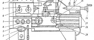
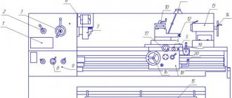
Main components of the machine (click to enlarge)
The controls are located on the side of the drilling head of the 2A554 radial drilling machine, which makes working on it convenient and efficient. The operator sets the modes before starting processing, which makes it possible to increase not only its productivity, but also the accuracy of execution.
Purpose of controls (click to enlarge)
Design features
This 2A554 radial drilling machine has a classic layout, which is represented by the following components:
- Foundation slab. This element is the base of the 2A554 machine, which distributes the load and receives the pressure coming from all components, the workpiece and the pressure created at the time of processing the workpiece.
- Column. On the machine in question, a column is installed, which is needed to ensure rotation of the traverse and movement of the head in the vertical axis. In the manufacture of the column, cast iron is used, which copes well with vibration and other loads. In addition, cast iron does not react to moisture, which significantly extends its service life.
- Traverse. It is located on the column and is designed to move the cutting tool with control elements.
- The working head is designed directly to feed the cutting tool. For this purpose, vertical guides are located on the traverse.
- The operating instructions provide the ability to rotate the head around an axis, which can significantly speed up work.
- This model's electrical circuit provides for the transmission of forces from various motors. The spindle gearbox receives force from the main motor through the drive mechanism. Drilling can take place at a wide variety of speeds, for which it is enough to switch on the required gear. The spindle drive, if the device is in good condition, does not produce much noise, but there is a possibility that if the drive is heavily worn, there will be problems with operation. The model can have quite a lot of malfunctions; it is important to carry out maintenance in a timely manner.
- The box table allows you to fasten a wide variety of workpieces, which may differ in shape and size.
- The main electric motor is installed on the traverse, another on the column.
- Control elements are represented by handles and buttons.
- Electrical wiring is hidden in special flexible pipes that can protect them from mechanical and other impacts.
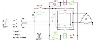
Electrical circuit of the machine 2A554
When considering the information that the manufacturer included in the passport, attention should be paid to the fact that the controls are located on the side of the drilling head. The operation of switching spindle speeds in the 2A554 machine, as well as other functions, is based on setting all parameters immediately before starting drilling. During drilling or other operation, you cannot set other parameters.
Drilling machine gearbox 2A554
Technical capabilities of the device
Thanks to a well-thought-out design and the use of high-quality components in its creation, the machine model 2A554 is distinguished by decent technical characteristics, ease of operation and high efficiency. Weighing 4700 kg and dimensions 266.5x103x343 cm, the radial drilling machine of this model corresponds to the “H” accuracy category, which is a good indicator.
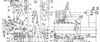
Kinematic diagram of the machine
Using this device, you can drill holes with a diameter of up to 50 mm in steel and up to 63 mm in cast iron workpieces. As stated above, using the 2A554 machine you can cut internal threads with a diameter of M52x5 for steel and M54x4 for cast iron.
The passport for the machine also indicates such parameters as the distance from the column to the spindle axis (375–1600 mm), as well as the distance from the end of the spindle to the work table (450–1600 mm). It is these characteristics that mean that it is permissible to process fairly large parts on this machine.
A notable characteristic of this device is the lifting speed of the traverse along the equipment column, which is 1.4 m/min. The machine crossbar together with the column can be rotated through an angle of up to 3600.
The dimensions of workpieces that can be processed on a 2A554 radial drilling machine are determined by the dimensions of the work table (102x255.5 mm). To expand the functionality of the machine, you can install an additional tool on the drilling head, the weight of which should not exceed 15 kg.
Workspace dimensions
The performance and functionality of this radial drilling machine is determined by the characteristics of the spindle head.
- The spindle rotation speed is in the range of 18–2000 rpm.
- Number of speeds – 24.
- Maximum torque – 710 Nm.
- Feed can be carried out in the range of 0.045–5.0 mm/rev.
- When performing a feed, a force of up to 20 kN can be created.
- The mounting hole in the spindle (Morse taper) is KM5.
Radial drilling machine 2A554 as part of a production line
To fix the moving elements of the machine in a certain position, two types of clamps are used:
- hydraulic (to stop the rotation of the column and move the drilling head along the traverse);
- electric (for braking the traverse as it moves along the column in the vertical direction).
The design of the radial drilling machine of this model is equipped with several electric motors responsible for the various movements of its elements: 5.5 kW – rotation of the spindle with the cutting tool; 2.2 kW – movement of the drilling head along the traverse. Five additional motors, which operate the coolant pump, are necessary to accurately fix the structural elements of the machine relative to each other and the workpiece.
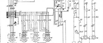
Electrical diagram of the power part of the machine (click to enlarge)
A friction clutch is installed between the gearbox and the main engine of the machine, which is responsible for turning on, off and changing the direction of rotation of the spindle.
Purpose, functionality
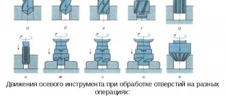
Radial drilling machines are widely used in both mass and individual production to form holes in parts made of metal, cast iron and non-ferrous alloys. The main movement in equipment of this class is the rotational movement of the working tool - the drill, and its reciprocating feed.
Radial units are designed to work with large parts that are unsuitable for drilling on conventional vertical machines due to the laboriousness of moving the workpiece across the work table. Unlike standard equipment, in radial mechanisms the part fixed on the table plane remains motionless, and the spindle with the working tool moves to the required position.
The functionality of the unit directly depends on the type of working tool mounted on the spindle. Thus, modern radial drilling machines can perform the following operations:
- drilling;
- countersinking;
- countersinking;
- deployment;
- boring;
- trimming ends;
- thread cutting (metric, inch)
The key characteristics of the equipment are three parameters: the maximum drilling diameter, the spindle overhang in relation to the bed and the dimensions of the work table, the last 2 determine the dimensions of the parts that a particular unit can process.
1.1 Radial drilling machine in operation (video)
1.2 Design features
Depending on the design features, all radial units are classified into three groups:
- universal (stationary);
- portable (used for processing large-sized workpieces, to which the equipment is supplied by a crane);
- self-propelled (moved on trolleys along rail tracks, fixed to parts using shoes).
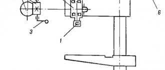
Design diagram of the radial machine 2E18P
The design of the machine consists of the following components:
- Foundation slab.
- Load-bearing column.
- Hydraulic clamp.
- Rotary sleeve.
- Traverse.
- Drilling head.
During processing, the drilling head can move both along the guide traverse and rotate within 360 0 due to the movement of the rotary sleeve. The part itself is installed on the workbench or directly on the foundation plate (depending on the design of the particular machine).
The column mounted on the foundation slab is made of a metal pipe. A lifting mechanism is installed on its upper part, moving the traverse in a vertical plane. The drilling head is a separate structural unit consisting of a speed unit, feed mechanism and spindle.
The drilling head in such equipment has a design similar to vertical drilling units, however, it has an increased number of feeds and revolutions. The increased spindle speed requires effective lubrication, which is provided by an automatic coolant system (a fluid reservoir is usually located inside the base plate).
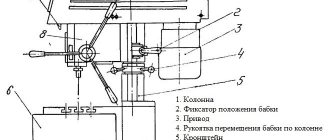
Torque is transmitted to the spindle from the engine through a gearbox consisting of gears. Asynchronous motors are used as a drive; 3-8 motors can be installed in one machine, each of which is responsible for the movements of a specific structural unit. For example: the common 2A553 machine has 7 engines (the electrical diagram shows the location of each drive):
Electrical circuit of the machine 2A554
- M1 - coolant pump motor;
- M2 - spindle motor;
- M3 — motor for accelerated spindle retraction;
- M4 - traverse motor;
- M5 — traverse hydraulic pump motor;
- M6 - speed dial engine;
- M7 - feed set motor.
This is interesting: Drill chucks for drills and adapters: types, features
How to ensure high-quality and uninterrupted operation of the machine
In order for the technical capabilities of the 2A554 radial drilling machine to be fully realized, it is necessary to properly prepare it for work. Such preparation consists of arranging a level platform for installing the machine, which should be able to support its weight. All structural elements of the device must be checked for visible defects. Only after this can you begin installing the equipment. The electrical network must be designed for the power consumption of the radial drilling machine, which is indicated in the technical data sheet.
Installation dimensions of the machine and foundation diagram
There are several simple rules, following which will allow you to work effectively and safely on such a device, maintaining all its original characteristics for a long time.
- Any emergency situation that arises when working on a radial drilling machine must be accompanied by its complete disconnection from the power supply. Only after this can you begin to diagnose and repair equipment.
- Cleaning the machine, changing the position of the workpiece, tightening threaded connections and other auxiliary operations can only be performed after it is turned off.
- During operation of the machine, it is necessary to regularly monitor the condition of the counterweight, which is responsible for the performance and precise functioning of the spindle assembly.
How to extend the life of the device?
If you follow some recommendations, you can significantly extend the life of the device. Let's take the following recommendations as an example:
- A level area should be constructed that must withstand the pressure created by equipment, tools and workpieces. Taking into account the fact that the weight of the machine is several tons, it is necessary to prepare the base.
- Before installation and operation, the structure should be checked for visible defects.
- When installing, take into account the high load placed on the electrical network. Thus, the total power of installed electric motors reaches 9 kW.
In addition, there are several recommendations that should be taken into account when operating this device:
- If any emergency occurs, the device should be completely disconnected from the power supply. Repairs and maintenance should only be carried out under conditions of complete blackout. This is due to the fact that during operation the device may move.
- Maintenance, repair, and adjustment work can only be performed when the machine is completely turned off.
- The design has a counterweight, which is responsible for the performance and precise positioning of the cutting tool. During operation, you should constantly monitor the condition of the counterweight, otherwise problems may arise.
You should also pay special attention to the selected cutting modes. So the cutting speed and feed rate determine the load experienced by the main components. As previously noted, all units are designed to withstand a load of no more than 20 kN. Otherwise, dimensional accuracy and surface roughness will deteriorate. The 2A554 radial drilling machine may have malfunctions related to the drives, coolant supply system, and the integrity of the electric motor device. Also, the fact that the workpieces are heavy determines the possibility of deformation of the body. In such cases, the positioning accuracy of moving structural elements significantly deteriorates.
Table of contents
The 2A554 radial drilling machine is designed for drilling holes in solid material, drilling, countersinking, and also tapping threads.
Increasing the productivity and functionality of the machine is possible with the use of devices and special tools that allow you to perform turning of internal grooves, cutting round plates, as well as work typical for boring machines.
Kronas fittings at affordable prices here!
Workspace dimensions
Design of a radial drilling machine 2A554
- Plate;
- Cooling system;
- Grounding;
- Electrical equipment;
- Base, column;
- Sleeve clip;
- Sleeve;
- Hydraulic clamp;
- Current collector;
- Hydro station;
- Gearbox;
- Lifting mechanism;
- Electrical equipment;
- Manual movement mechanism;
- Steering device;
- Spindle;
- Feed mechanism;
- Friction clutch control;
- Electrical equipment;
- Accelerated spindle retraction;
- Counterweight;
- Head clamp;
- Pumping station;
- Lubrication system;
- Hydrocommunications;
- Main cylinder;
- Gyro selector drive;
- Hydropremelector;
- Friction clutch;
- Gearbox;
- Feedbox 24 speeds;
- 12 speed feed box;
- Drill head;
- Hydropanel
Kinematic diagram of the radial drilling machine 2A554
Spindle of radial drilling machine
The spindle of the machine 1 is located in a retractable quill 5. In the front support, in addition to two radial ball bearings, there is also a thrust bearing 3, which takes up the axial load when drilling.
The rear support contains radial and thrust bearings 7 and 6, respectively. The thrust bearings are tightened through the support washer 8 with a nut 9.
The transmission of rotational motion from the gearbox to the spindle is carried out through its tail part, which mates with the gearbox sleeve with splines.
The lower part of the spindle has a Morse taper 5 for mounting the cutting tool.
The quill of spindle 7 has a rack cut into it, designed to transmit the feed movement. A special key 12 ensures that the spindle stroke is limited, the end of which fits into the groove of the quill.
Pin 2 serves to stop the spindle in extreme positions, which acts on microswitch 10, opening the power supply circuit of the electric motor.
Drilling head of the machine
The drilling head consists of several assembly units. The gearbox and feeds are located in the upper part of the head. The hydraulic system control panel is attached to the rear plane. In addition, the head is equipped with electro-hydraulic pre-selection (pre-selection) mechanisms. Allowing the next technological processing mode to be carried out even before the end of the previous one.
It is placed on the sleeve guides, along which it can easily move in the radial direction.
Ease of movement is ensured through the use of combined rolling-sliding guides. In the pressed state, the gap between the guides of the head and the sleeve is 0.03-0.05 mm, and along the upper guides the head moves along the rollers.
Rollers 1 and 4 are mounted on ball bearings 13 on eccentric axes 12.
The gap between the guides is adjusted using eccentric axes 17.
Radial drilling machine gearbox
The drilling machine's gearbox is designed to transmit 24 rotation speeds to the spindle. Different spindle rotation speeds are provided by switching the corresponding moving blocks. A friction clutch is located on the first shaft, which serves to connect the kinematic chain between the electric motor drive and the spindle.
The machine's gearbox is connected to the upper clutch by gear blocks 3 and 4, and to the lower clutch by gear 24, mounted on shaft 10, through idler gear 23.
Smooth and quiet operation, as well as the transmission of high loads, is ensured by making all gears and gears from high-quality steel, hardening and subsequent grinding.
Feed box for radial drilling machine
The feed box of the drilling machine is located between the spindle and the feed mechanism and receives rotational motion from the spindle through gear 1.
The lower supports of shafts 6 and 7 are sockets located in the intermediate plate 4.
On shaft 7 there is a selector gear 3. An additional selector group is located in the feed mechanism.
Radial drilling machines - overview of models
Radial drilling machines are used to drill through and blind holes in metal or wooden parts, as well as to perform a number of auxiliary operations - countersinking, boring, reaming and threading.
Radial drilling machine
This article provides information about radial drilling units. We will study their functional purpose, scope of application, design features and consider popular equipment models.
Functions performed by the RSS
The improved model has a maximum list of functions that previous versions could not accomplish:
- drilling;
- thread cutting;
- trimming ends;
- countersinking;
- boring;
- deployment.
When processing parts, especially oversized ones, the following parameters are taken into account:
- minimum and maximum drilling diameters;
- spindle overhang length;
- surface dimensions.
Machine 2A554 radial drilling type: functions and device
The Odessa ZRSS 2A554 model is a classic representative of radial drilling equipment, effective when it is necessary to metalwork large and medium-sized metal parts. These machines are large-sized and professional and have an appropriate price; they can be purchased at a price of 1,500,000 rubles and above; in used condition they are also expensive. The need for their installation must be justified; all design features and characteristics should be familiarized with in advance.
Device functions and tasks
A distinctive feature of the 2A554 radial drilling machine is the presence of a rotating column with a multifunctional working head, rotated 360° and processing stationary workpieces fixed on a heavy and stable base with dimensions up to 1600 mm, that is, medium and large. The high number of degrees of freedom of the spindle, coupled with good overload protection, reduces the time of drilling operations and increases their productivity significantly; in terms of saving energy costs, the 2A554 compares favorably with models that move massive parts on the work table.
The technical capabilities of the machine allow you to perform a variety of operations with fairly high accuracy (class H according to GOST 8-82): drilling through and blind holes, countersinking to improve roughness parameters, drilling and boring previously created, including those obtained by casting, rolling threads using taps . Provided that additional devices are attached and a special cutting tool is used, the functions of the model expand to preparing grooves, cutting round plates from thin sheets of metal, forming holes with a square cross-section, grinding in cylinders and valves, and performing other actions inherent in boring-type models.
Main common models
Among the models that are most similar in functionality to PCC are:
- GS535;
- 2K550;
- 2L53;
- 2N55.
The above list is far from complete; there are other units with a drilling diameter of 5 cm or more for metal and 6.3 cm for cast iron. Modern analogs of RSS are products of the Sterlitamak plant, Gomel hub plant, and Astrakhan plant. The passport and indicators of models may change; it is necessary to clarify the indicators in each specific case.