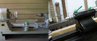
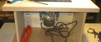
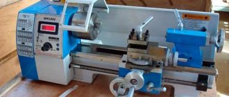
We propose to build a metal lathe with your own hands with smooth adjustment of the spindle speed.
To create such a small metal lathe, you will need spare parts from various faulty power tools.
The machine is small in size and has a powerful engine.
The manufacture of the speed controller will be shown in step 5.
The video below shows a miniature metal lathe in operation at various speeds. The coupling causes vibration, which becomes greater as the number of revolutions increases.
There is another video in step 9.
What is the tool used for?
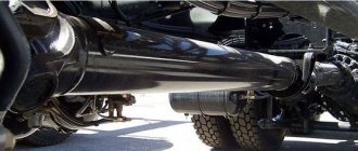
The pressing device is used during brake system repairs.
When the caliper is removed from the disc, the rod remains in the pressed-out position and does not allow the part to be installed back.
To complete the repair, you need to press it into place. Many car enthusiasts use for this purpose everything that is at hand: a vice, keys, etc. However, you can make a special device that will greatly facilitate the task.
The piston is pressed down due to a screw-in worm mechanism.
Step-by-step device assembly process
When all the necessary parts have been turned, it is necessary to assemble them into a single structure.
The parts of the future tabletop lathe are assembled on the assembly table.
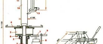
It was decided to make the structure from flanges machined from round timber with a diameter of 120 mm. To make them easier, a central hole of Ø 55 mm is drilled in them. There are three holes Ø 20 mm.
Additional holes for threaded fasteners are drilled at the end. M6 screws can be used to secure the remaining parts in a given position.
A bronze bushing is pressed in for the future lead screw. Internal Ø 16 mm.
The bed guides are made of ductile cast iron. They have longitudinal grooves. The cylindrical part allows it to be fixed in the flange holes.
The guide is inserted so as to combine all the existing elements.
To maintain a given distance, spacer bushings are used. They are installed in the spacer between the flanges.
The second guide is made exactly the same as the first.
Having assembled the base for the headstock, proceed to assembling the rear one.
The frame is tightened with nuts. The foundation of the future bed has been created.
The machine will stand resting on the front supports. They are secured with screws to the flanges.
Support bushings move along the guides. The caliper and tailstock will be mounted on them. The long sleeve acts as a guide, and the short one acts as a support. The grooves on the rollers do not allow them to move.
Structurally, the support bushings are made of different lengths. This solution allows you to increase the working stroke.
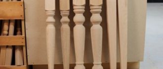
The length of the processed parts can be sufficient so that the parts have dimensions up to 250 mm.
The caliper platform is secured with M6 screws.
The holes for the platform are drilled in place. This part is made individually. If you try to make it only according to the drawing, a jamming effect may appear.
By analogy, the tailstock platform is made. It is also drilled in place. It is necessary to ensure sliding movement along the guides.
It is necessary to ensure the rigidity of the frame. A special cylindrical half ring is machined for the headstock. It is bolted to the flanges.
The movement of tools on the support or tailstock is carried out by a lead screw. A rectangular thread with a slight slope (12.5 ⁰) is machined on it. When the lead screw rotates, the parts attached to it move forward or backward. Depends on the direction of rotation.
A hole with a pressed bushing was created for the lead screw.
To ensure that the screw rotates freely, but does not itself move along its axis, thrust bearings are used. They are placed in front and behind the rear support.
To prevent axial movement of the lead screw, a locking sleeve is installed. It is secured with an M6 bolt. Now the screw will not move along the axis, but it can rotate.
A vernier (a device with notches) is placed on top of the fixing sleeve. One turn of the screw moves the caliper or tailstock 10mm. Using the scale as a guide, precise displacements can be made in the longitudinal direction.
To rotate the lead screw, a handwheel is installed. The small handle allows you to easily rotate the flywheel.
Risk helps you navigate. Looking at it, the desired axial displacement is set.
The machine bed is assembled. Now you need to install the headstock. The part will be recorded in it.
Transverse movement guides are installed on the plates.
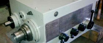
The headstock is mounted on top. The picture shows a pulley block, a three-jaw chuck and a central bushing.
The pulleys can be easily removed and installed on the spindle.
The spindle itself is installed inside the central bushing.
There are radial bearings between the spindle and the bushing. They allow free rotation.
The central bushing is bolted to the frame.
After installing the bearings, a spindle with a three-jaw chuck is mounted. A hole Ø 35 mm is machined inside the spindle. If necessary, workpieces of smaller diameter can pass through it.
The machine is ready. The drive is carried out through V-belts from an electric motor installed to the side.
Video: DIY mini lathe.
How to make it yourself
To make the device yourself, you need to prepare three nuts, a long bolt and old pads.
The whole process will consist of four simple steps:
- Take a drill according to the diameter of the fastener and drill a hole in the block exactly in the center.
This tool is only suitable for front calipers. For the rear ones, you need to add a special hook to the end of the fastener, which will rotate the rod.
Center rotating
A rotating turning center is used for fixing workpieces with rotating bodies on the tailstock of a metalworking machine. The design of this type of equipment allows processing at high speeds with minimal runout. Rotating centers can be used on lathes and grinding machines with manual, semi-automatic and numerical control.
Design of rotating centers
The figure above shows the design of the center intended for fixing the tailstock quill of a lathe into the conical groove. The working part or center (1) rotates thanks to ball bearings (2) and (4); in other design options, needle bearings are used. The axial pressure arising during operation is compensated by the thrust ball bearing (5). Fastening in the quill is provided by a conical shank (3). To accurately determine axial forces, some designs have a built-in device.
More reliable fixation of workpieces, especially when working with heavy parts at high speeds, is ensured by centers built into the quill. This design, shown in the figure below, provides higher fixation rigidity, which is optimal when preparing large-section chips.
There is a specially bored hole in the front part of the quill (1). It contains bearings for the sleeve (4) - thrust (3) located in the front part to absorb axial load and radial (2). A conical hole is machined in the bushing for the center (5). This design can be used to attach a drill or any other axial tool, for which the sleeve is connected with a stopper to the quill.
Scope of application and features
Rotating centers are used in lathes for turning parts at rotation speeds of more than 75 m/min. At this speed, the process of increased wear of the center cone and the center hole of the workpiece begins. A partial way to solve the problem is to use lubricant and carbide tips, but the best option is to use a rotating center.
Main advantages of the equipment:
- Versatility. When using centers with replaceable attachments, parts with different conical axial holes can be processed.
- High load-bearing characteristics, significantly exceeding those of thrust clamps.
- Long service life due to reduced wear.
- Ability to work under high loads.
The main disadvantage is the presence of radial runout. This problem can be solved by using equipment with an acceptable runout indicator, or finishing at low speeds using a fixed center.
Types of rotating centers
Depending on the shape of the fixing part, two types of rotating centers are available:
- with a working cone for fastening workpieces with center holes;
- with mushroom-shaped attachment for workpieces with an internal hole - pipes, hollow shafts, etc.
By design, the equipment is divided into:
- Center with permanent roller (type A)
- Center with replaceable nozzle (type B)
The cone of the center roller is machined at 60° (version 1) or may have an additional groove for a 30° cone (version 2).
Symbol of equipment: Center A-1-4-NP GOST 8742-75
Type A, version 1 with Morse taper 4 of increased accuracy and normal series.
Table of basic equipment parameters
| Rotating machine centers GOST 8742-75Type A - with a permanent center rollerType B - with an attachment on the center roller | |
| Center rotating type-version-Morse taper-series | |
| Rotating center A-1-2-N | Rotating center A-2-2-N |
| Rotating center A-1-3-N | Rotating center A-2-3-N |
| Rotating center A-1-4-N | Rotating center A-2-4-N |
| Rotating center A-1-5-N | Rotating center A-2-5-N |
| Rotating center A-1-4-U | Rotating center A-2-4-U |
| Rotating center A-1-5-U | Rotating center A-2-5-U |
| Rotating center A-1-6-U | Rotating center A-2-6-U |
Features of operation
Here are the basic rules for operating rotating centers necessary for precision machining of parts:
- When choosing the accuracy class of the equipment, it is necessary to leave a margin to cover runout errors due to other reasons - wear of bearings, low rigidity, etc.
- Correct installation of the part is important. The axis of the cone must coincide with the axis of rotation of the workpiece with high accuracy.
- To check the accuracy of the installation, you can place a white sheet of paper under the rotating center and evaluate the alignment. More precise control is carried out using indicators.
- If there is runout, the cone is ground in place and checked using a template. Processing is carried out with a power tool located in the tool holder.
- The beating of the rotating centers leads to the beating of the resulting part relative to the axis. When installing this part on another machine that has a different runout, a deviation from alignment may occur. To eliminate deviations, processing is carried out using a fixed center.
Current GOSTs
The main parameters of rotating centers are regulated by GOST 8742-75. The general standard governing centers and half-centers of lathes is GOST 13214-79.
Source: https://MekkaIn.ru/library/czentr-vrashhayushhijsya.html