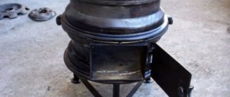
You can prepare many delicious and satisfying dishes while hiking. One of these is oriental pilaf. It is on the fire that it turns out especially fragrant and refined. Its preparation requires adherence to certain rules, without which pilaf will be ordinary porridge. One of these conditions is temperature. In the case of a fire, maintaining the fire at a certain level is quite difficult. Here you will need to continuously monitor the flame, and this is very tiring. If you decide to cook pilaf in a cauldron outdoors, you can build a special burner for this. It will run on gas, so you can monitor and vary the flame level. In addition, such a device will not leave soot and soot on the surface of the cauldron.
Gas type/pressure
For heating, both natural gas (methane) and liquefied gas (propane - butane) can be used. Natural gas is supplied through low pressure gas pipelines. Propane - butane can be used for autonomous gas supply with the installation of a gas holder or supplied in propane cylinders. Heating experience with the use of propane cylinders.
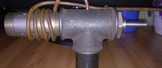
Burners can be designed for a specific type of gas, or they can be universal. In order for gas to burn correctly, it is necessary to mix it with air in a certain proportion. This proportion is different for different types of gas. The burners operate with a special device that ensures the correct amount of gas is supplied to the combustion chamber depending on the air pressure in it. This device is called a gas train, gas fittings, proportional supply device. The air pressure in the combustion chamber depends on the burner options, the draft in the chimney and the resistance provided by the boiler and chimney to the air clot. Changes in ambient temperature affect draft; contamination changes resistance to the clot. So it’s impossible to do without automatically adjusting the gas supply.
In some burners, to switch to another type of gas, it is necessary to change the gas fittings. In others, it is necessary to install or remove a special diaphragm in the gas supply channels. It may also come in handy to replace the manifold. There are universal burners. Conversion to another type of gas is carried out by adjusting the gas train and air supply.
In any case, you need to make sure that the burner you buy is suitable for your gas. Conversion to another type of gas price can be up to 50% of the burner price.
Gas burners have restrictions on gas inlet pressure. Some can operate at completely low pressure. Others require some level. There is a relay installed at the inlet that turns off the device when the pressure is very low. This relay can be adjusted. But there is some slight pressure. It is justified by the design of the gas fittings. Below this pressure the burner will not work. About dilemmas with low gas pressure.
What to look for when choosing?
If the purchase of a device is due to the desire to convert a solid fuel boiler to gas fuel, its power should significantly exceed the power of the firebox.
It is also necessary to take into account the compatibility of the boiler and burner.
So, for example, not every “solid fuel” can be converted to install a fan burner, and in boilers such as, for example, “DON”, it is impractical to install them due to insufficient thermal insulation of the boiler tank.
The nature of the movement of the gas-air mixture has an important influence on the operation of the burner. Based on this feature, these devices are divided into straight-flow and twisted. The latter are characterized by a more powerful air flow.
Classification and requirements
Let's start with the 2nd position, in other words, with the requirements that are now imposed on gas burners for boilers.
- First, they need to be used to accurately combine the air-gas mixture. This is precisely their main purpose. In this regard, manufacturers make every effort to achieve one hundred percent results. Modern burners contain new developments and technologies that maximize the efficiency of natural gas combustion.
- These devices should be easy to install and easy to remove. No unnecessary fancy fastenings. Everything is very simple and secure.
- Highest durability. Let's put it this way: while the gas burner should also work . At the same time, quality indicators should not change over time. That's why these units are made from high quality materials.
- They must meet the requirements of sanitary and hygienic standards. Particular attention is paid to their silent operation.
- Currently, manufacturers offer so-called combined designs that can operate on different types of fuel. For example, diesel gas, main gas - liquefied gas. And even here there are some requirements. One of them is a rapid transition from one type of fuel to another.
- Not the least important indicator will be the low toxicity of emissions from fuel combustion. Engineers and designers are trying to reduce this indicator by changing the design of the burner, in which the gas-air ratio will be optimal. This is what will influence the reduction of emissions toxicity. By the way, toxicity refers to the amount of carbon monoxide (carbon monoxide) and nitrogen oxide in the products of fuel combustion. The more there are, the worse it is for the surrounding nature.
Automatic burner
Burner brands for testing
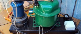
Industrial waste oil burner
A waste oil burner in a Western-made solid fuel boiler is considered the most economical. In terms of its technological qualities, it must meet the certification requirements of the Russian Federation.
The most popular burner designs for burning waste petroleum products are the following brands:
- American and Canadian burner: Energy-Logic, CAEQ.
- German and Austrian modules: Euronord Eco-Logic, Giersch.
- Italian nozzle: Eco-flam, Master MB.
- Korean multifunctional burner: Olympia AL.
- Chinese and Polish burners are of approximately the same technological range: Smart-Burner, NORTEC-WB, Hiton.
The best models of Russian manufacturers of burners for spent fuel:
- Universal burners Gnome-Economy, 10-35 kW, 45,000 rub.
- OLYMPIA AL-4V-2 (25-45 kW), made on the basis of an OLB burner from South Korea, RUB 132,000.
- Universal burner Teplamos Eco 50, 93,000 rub.
- Waste oil burner Heat 800-2000 kW, 230,000 rub.
- Waste oil burner Brest 500 kW, 125,000 rub.
Manufacturing Features
The design features are that it is very easy to operate; there are no traces of soot or repulsive odors when using the gas burner. This device is compact and can be used virtually anywhere. The main component of the burner is the industrial valve. You can purchase a new part, however, and used ones that are in working order are quite suitable. The process of making a burner with your own hands begins with the handle, then the body and nozzle are made.
A homemade device can be made using propane, butane, or a propane-butane mixture. That is, the device can only operate safely on gas-like saturated hydrocarbons and air.
a burner that is safe to use and does not waste fuel , you need to make it a rule to avoid scaling and adjusting the example circuits.
To be fair, it is worth noting that not all gas appliances are calculated according to the laws of gas dynamics. But if the manufacturer changes the dimensions of the design parts, then the Reynolds number of the fuel (or intake air) will go beyond the limits indicated in the original product. The burner with such “improvisation”, if we give an optimistic forecast, will begin to smoke and will be “gluttonous”, or even be completely dangerous in operation.
And one more important note regarding the manufacturing features of the burners: it is impossible to increase its power above 10 kW. And that's why. With a burner efficiency of 95% (which is an excellent indicator for an amateur invention), with a device power of 1 kW, it will take 50 W to self-heat. It is theoretically possible to get burned on the structure, but it is not fraught with explosion. But if you build a burner with a capacity of 20 kW, 1 kW will be superfluous. Threshold manifestation is expressed by the structure being hot or bursting into flames. Therefore, those burner drawings that are oriented at 7-8 kW should not be considered.
Starting the furnace
It has already been said implicitly that you need to start the drip furnace slowly and smoothly. Usually, for this they use a torch made from a knitting needle with a piece of foam rubber or a rag: let some drops in and place the torch. When it gets wet, they wait until a puddle drips into the bowl, light a torch, and pour oil into it.
There is a much more convenient and safer way to start a drip stove: a wad of toilet paper soaked in the same oil. They put it in a bowl, set it on fire and slowly regulate the drips, no longer worrying about kindling. Toilet paper is almost pure cellulose; it burns without leaving a residue. Tourists have been warming themselves in tents this way for a long time: the roll is inserted into a wood chip stove, poured with half a glass of alcohol (which also burns without a trace), or the whole thing, darling, and set on fire from above. A lot of heat is generated, and an insignificant amount of fluffy ash can simply be blown out. In the oven it will fly out into the chimney.
How to make a gas burner
In the diagram below you can see exactly how a gas burner . Such a device will require the following components:
- The body, which is made in the form of a double truncated cone. Its manufacture requires high-strength steel.
- Confusion bell made of steel X18N9T, resistant to high temperatures and open flame.
- Heads for supplying natural or liquefied gas, as well as air at the required pressure to the work site.
- Mouths.
- Regulators that allow you to adjust the amount of gas and air in the mixture.
One and a half inch pipes and heat-resistant steel sheets will help complete the main elements of the device. For this purpose, welding is used in an argon environment, but you can also use flux, which will protect the seam from exposure to oxygen and rapid corrosion. We use ordinary high-pressure hoses as pipes for supplying gas and air. The main thing is to choose the right diameter. The connection to the body is made using metal clamps.
To prevent gas leakage and pressure loss, reliable sealing elements will be required. They can be made of rubber that can withstand aggressive chemical influences.
About converting a blowtorch for testing
Some home craftsmen, having studied the operating principle of the Babington burner, are trying to convert an ordinary blowtorch to burn waste oil. The goal is to reduce the cost and simplify manufacturing, because the processes in these two devices are supposedly similar. This opinion is erroneous, since a blowtorch functions differently than the homemade burner described here.
In the lamp, air is pumped into a tank of gasoline with one purpose - to push it out and deliver it to the nozzle. In this case, the fuel goes through the stage of heating and evaporation. The nozzle supplies gasoline vapor to the combustion zone; the liquid can be observed there only at the ignition stage, when the “head” of the blowtorch has not yet warmed up. The used oil will not be able to evaporate and the nozzle will supply it in the form of large droplets, which does not contribute to normal combustion. And the cross-section of the jet will quickly become clogged with various impurities.
The conclusion is simple: it will not be possible to convert a blowtorch to burn heavy liquid fuel.
Types of burners used for gas combustion
The choice of the optimal design of the forge burner is related to the issues of the amount of metal waste during heating for forging, the intensity of surface scaling, as well as the total gas consumption. Closed-type furnaces require short-flame burners that provide rapid and intense mixing of the combustible mixture. It is then that the efficiency will be maximum, and the removal of combustion products from the working chamber of the forge will be uniform and efficient.
READ DIY brick pizza oven
Thus, the gas burner must provide:
- The greatest angle of inclination of the finished gas-air mixture at the entrance to the working space of the forge.
- High jet exit speed with a low height and large width.
- Gas ignition safety.
- Stability of the combustion process.
- Insensitive to high humidity inside the forge.
- Safety during the so-called “reverse strike”, when a sudden change in the direction of thrust can extinguish the torch, which almost immediately leads to an explosion of the flammable mixture in the furnace.
Thus, for burning propane (from a cylinder or gas pipeline) the following are used:
- Injector burners providing self-suction of gas. Despite their simplicity, they are characterized by low efficiency, since they allow adjustment of the ratio of components for a relatively small range of values. Regarding a home-made forge, this most often leads to the need to work with a lack of air;
- Burners are tangential type (point jet), when the gas flows along the axis and the air flow tangentially to the mixer body. Mixing here occurs quite intensively, but pressure losses due to turbulence are also large. This affects the unevenness of the amount of air supplied to the forge, and it is greatest where the heated metal comes into contact with the hearth bottom. Accordingly, waste and scale formation increase. The positive quality of tangential burners is their simplicity and reliability;
- Vortex burners, where spiral guide plates are used to mix the flows. In such options, complete mixing occurs only at the mouth, so control by operation in this case is the best, and there is practically no pressure loss. Some of the disadvantages are the design complexity, which is why, even with drawings, making a vortex burner for a forge in a home workshop is very labor-intensive;
- Combined burners that combine tangential and direct-flow supply. The adjustability of the combustible mixture is the best, since by changing the amount of air supplied between the internal and external channels, you can adjust the length of the torch in the forge and, therefore, control the heating time of the workpieces for forging. The disadvantage of such designs is their large dimensions, which may be unacceptable for small forges. Also, the technical complexity of manufacturing a dual-flow burner can be considered a minus.
Description of the operating principle
The operating principle of a gas burner is based on the directed supply of a mixture of gas and oxygen. At the same time, the feed torch maintains a constant shape and temperature. As a result, after heating the 2 surfaces, a hermetically sealed connection is formed using molten solder. This material must have sufficient adhesion, adhere well to hot surfaces and be durable after cooling. The gas burner provides the temperature of the solder so that it becomes viscous. In this case, the total heating should not exceed the melting point of the base material.
In some cases, slight heat is applied. This is required when you need to dismantle a part that is press-fitted. For example, a bushing or a bearing. This is especially applicable to cases where parts have different expansion coefficients. Heating is also used in work when welding cannot be used.
How to check the operation of homemade equipment?
The result of long-term work on choosing a boiler design and implementing this project will be an economical and reliable source of heat. A well-functioning boiler has the following qualities:
- Correctly selected power. Pyrolysis has a small range of adjustments. The boiler cannot be “strangled” or “overclocked” too much. In this case, combustion either stops altogether or begins in the gasification chamber. Therefore, the boiler power must correspond to the heat loss of the house.
- Possibility of long-term operation in forced mode. One bookmark should be enough for a long time.
- Easy access to gasification , a pyrolysis torch in the afterburner should be observed within 15–20 minutes after ignition.
- The temperature of the gases in the chimney should not be higher than 40–60 °C. If the temperature is higher, we increase the area of the heat exchanger.
- When testing the boiler after going into pyrolysis, only carbon dioxide and steam should come out of the chimney. The presence of dark smoke and odor indicates incomplete combustion of fuel.
Drawings and step-by-step instructions for making a burner
Let's take a closer look at the nuances that you should pay attention to when making a burner.
- First of all, it is necessary to use refractory metals. A properly configured burner can produce up to 1000 ° C, so the nozzle must match the flame temperature;
- It is important to choose a reliable working crane. If something goes wrong, the gas supply is first cut off and the danger is eliminated. If the tap leaks, you will not be able to quickly extinguish the flame;
- The connection point to the gas source (a bottle with a valve or a 5 liter propane bottle with a reducer) must be reliable. It is when operating low-quality shut-off valves that most accidents occur.
Let's consider a typical diagram and principle of operation of an injection burner:
Gas is supplied under pressure through the hose (1). Typically propane. The pressure is formed due to the evaporation of liquefied gas in the cylinder, and it is sufficient to organize a stable and directed flame. A reducer is not required, the amount of gas is regulated by the operating valve (2).
The shut-off valve is located on the cylinder valve. Its function is only to open/close the fuel supply; other adjustments are made using a working tap.
The gas supply tube (3) leads the jet into the nozzle and ends with a nipple (6), which sets the direction of the flame. The nipple with the tube, in turn, is located in the so-called insert (5). It organizes the mixing of gas with atmospheric air.
The insert with a tube and nipple is fixed in the nozzle with a screw. As a rule, the burner is dismountable for cleaning and maintenance of the nipple.
The formed air-gas mixture is directed to the nozzle of the nozzle (8), where the mixture is additionally saturated with oxygen from the air. For combustion stability, ventilation holes (7) are provided.
You can make the burner yourself according to the drawing.
Dimensions are designed to work with cylinders up to 5 liters.
We will tell you about the structure of the liner separately; the drawing shows all the necessary dimensions:
The outer diameter of the liner tube (1) should be half a millimeter smaller than the inner diameter of the nozzle. A washer (2) with holes for air supply is welded inside. The sleeve (3) is designed to fix the tube with the nipple.
The peculiarity of the design is that by moving the tab inside the nozzle, you can regulate the air leak through the ventilation holes. This allows you to regulate the flame temperature over a wide range. The nozzle can be made from a steel pipe, but it would be better to turn it from a steel blank on a lathe. The shape of the nozzle should be somewhat narrowed at the outlet, then the flame will be forced and the temperature in the combustion zone will be higher. Alloy steel grade 45 is used.
There are two ways to make an insert: You can assemble it from two tubes and a steel washer with holes. The structure is soldered with refractory solder, with abundant fluxing. Or you can grind it entirely from a steel blank. The second option is preferable.
The supply tube is copper or brass. On the side of the hose connection, a flange is made (concentric grooves can be made for better fixation). A suitable nipple is screwed into the working end. You can take it from a primus stove, or a gas burner from a household stove.
The second option will suit us. When the burner is ready with your own hands, it is necessary to carry out initial debugging.
The burner is set to use the gas that will subsequently be used. The insert is lightly secured with a screw so that the ventilation holes are blocked by half.
By slightly opening the operating valve and moving the insert, we achieve an even, powerful flame. Then we finally fix it in the nozzle.
If you did everything correctly, the temperature at the outlet of the nozzle will reach 1100° C.
Let's move from theory to practice. How to make a gas burner using available materials:
The nozzle is made from a classic car pump design. Such items often lie idle in the garage. The steel used is excellent and the size is suitable for a gas burner.
Powerful gas burner for Wok and Kazan (18 kW, natural gas)
We cut a “rose” in the back part, bringing the ends to the center. A feed tube will be inserted into this bundle.
The part came from a construction foam gun. This is a device for reusable use, so the steel is strong and coated with refractory chromium.
The thickness of the tube is almost 1 millimeter, which is quite enough for rigidity.
At the end of the gun tube there is a nozzle with a ball valve to form foam. The ball is knocked out with a thin awl or gypsy needle. The resulting hole is sufficient to supply gas to the nozzle. The tube with the nozzle is connected using semi-automatic welding.
- To connect the structure to the working faucet, conventional plumbing fittings with threads were used. This is a simple water pipe; no special steel is needed. The part of the burner where the tap is located does not heat up to critical temperatures. ball gas valve;
- The holder is literally made from scrap metal. Handle from a motorcycle footrest. By lightly processing it with a grinder, we get the optimal shape. The clamp for attaching to the burner pipe is from the handlebars of the same motorcycle.
Finally the holder fits on a motorcycle handle. The thermal insulation is good, and the burner fits snugly in the hand.
It took one weekend to make and 100-120 rubles to buy a tap and a fitting for connecting to a hose.
READ Geyser clicks after switching on
A gas burner for soldering is made from a needle from a dropper. Connects to a lighter refill bottle.
Conclusion! A homemade gas burner is a reality. Just be careful when operating!
A simple and effective way to make a gas burner with your own hands - video
Installation prices are always affordable for our customers. They are completely confident that they will not be deceived here and will advise the right decision. Trust is the key to the success of our company! And high-quality materials from well-known manufacturers and the skillful hands of our professionals leave no doubt that the installation will be completed on time!
Another plus - when concluding a contract, you receive an estimate that takes into account the prices for roofing work and materials, as well as the cost of delivery in Moscow and the Moscow region, accurate to the ruble!
You can make a gas torch for soldering yourself. The design has different configurations. Often the dimensions do not exceed the length of a ballpoint pen. It is used to heat up metal for the purpose of subsequent hardening or welding. In some cases, a burner is made to heat the bitumen on the roof. Homemade devices are much cheaper than purchased analogues.
Conclusions and useful video on the topic
The video will talk about how to make a propane gas burner yourself:
Having at hand a small supply of tools, a gas burner diagram and the necessary materials, every home craftsman can assemble a propane burner. It is important to follow fire safety rules and use only high-quality materials approved for use in the domestic gas supply system. But if you are not confident in your own abilities, it is better to purchase such a device in a store.
If you had to assemble a propane burner yourself, please share your knowledge with our readers and tell us which option you chose. Why was he chosen and were there any difficulties during the work process? Perhaps you have a diagram of the device and a photo of the finished homemade product - include visual information in the discussion of the material.
DIY natural gas burner
In a home workshop or garage, there is often a need to use a gas burner. It has the widest range of applications – from soldering to roof repairs. Not to mention the need to heat up the metal part for processing.
When doing metalworking work on metal, a gas torch can be used to heat the workpiece for the purpose of subsequent hardening. If you are engaged in electric welding, when working with some metals it is necessary to warm up the area of the future weld.
Or a multi-nozzle ramp for heating bitumen on the roof:
Device using two needles
A miniature propane torch is made by hand from 2 needles. One needle can be taken from the pump and the other from the syringe. You will also need two droppers and a compressor from the aquarium. The device is connected to the canister for charging lighters. You will also need copper wire.
The temperature in such a burner reaches 1000 degrees. It is made in the following order:
- A hole is drilled in the middle of the larger needle, which should be slightly larger than the diameter of the smaller needle.
- The syringe needle is inserted into this hole so that it is a few mm deep. came out of the end of a larger needle.
- The joint is sealed using copper wire and subsequent soldering.
- On both opposite sides, the needles are connected to 2 droppers.
- The opposite end of one of the droppers is connected to a lighter cartridge.
- The end of the second dropper is attached to the compressor.
- All joints are tightly sealed.
The gas coming from the can is mixed in a thick needle with air coming from the compressor. The composition of the mixture is changed by regulators.
If there is no compressor, you can replace it with a plastic bottle:
- A hole is made in the bottom of the bottle and a nipple or spool is screwed into it.
- A hole is drilled in the bottle cap and the body of the syringe is inserted into it without a piston and needle.
- This place is sealed.
- The cap is screwed onto the bottle.
- The body of the syringe is connected to a system connected to a thin needle.
- Air is pumped into the bottle through the nipple.
How do top loading gas generating equipment work?
Firewood in a top-loading pyrolysis boiler burns like this:
- The loaded firebox is ignited , the flame on natural draft heats the firebox to a temperature in the primary chamber of 60 °C.
- The door is closed and the primary air supply is turned on. Within a few minutes, the temperature in the combustion zone reaches 600 °C - the optimal mode for the decomposition of gases. Firewood smolders when there is a lack of oxygen.
Photo 1. The firebox of a pyrolysis boiler is loaded with firewood; the flame heats it up to 60 °C with natural draft.
- Air, previously passed through the flame of the primary chamber, is supplied to the secondary chamber. Hot gases mix, resulting in a mixture with a stoichiometric number - the optimal ratio of air and combustible gas.
- Passing through the nozzle, the mixture ignites and burns, releasing a large amount of heat. Part of the heat is spent to maintain combustion in the primary chamber.
- The heat is captured by a system of heat exchangers, and the released carbon dioxide is removed through the chimney.
DIY process
To make homemade equipment, you need to take into account some nuances:
- The device output temperature is 1000 degrees. Therefore, refractory metals are used in manufacturing.
- An important condition for safe work is a reliable crane. In the event of an accident, it should quickly shut off the air flow.
- Reliability of the gas connection.
You can make a manual gas torch for soldering with your own hands in the form of a miniature device. To make such mini-equipment you will need the following materials:
- brass or copper tubes;
- block of wood;
- silicone or fluoroplastic as a sealing material.
The drawing of the device consists of a body in the form of a pipe ending with a nozzle. On the other side, a gas supply hose is installed. The nozzle is equipped with a divider to adjust the flame.
gas torch for soldering is made in the following order:
- To make the burner body, brass is used in the form of a piece of tube. The length is selected based on ease of use.
- The used soldering iron base is used as a handle, or it is made from a block of wood. A hole for the nozzle is drilled in the axial part. It is fixed with epoxy resin.
- The tap is attached to the tube using silicone.
- On the other side, the tube is plugged and a 0.2-0.3 mm hole is made in it. For this, a special drill and chuck are used.
- After this, the burner is clamped in a vice and the hole is flattened to 0.1 mm using a hammer.
- All burrs are removed with sandpaper.
The divider can be made from a brass tube that is larger than the diameter of the burner. The fastening is parallel to the body. The system will operate on the principle of a tourist stove. In the place where the gas leaves the nozzle, a vacuum is formed and air is sucked in.
homemade gas burner (natural gas)
Drilling holes
In order for the air flow to atomize the fuel as efficiently as possible, the hole should be as small in diameter as possible. The priority is 0.010 inches. Although holes up to 0.020 in size are also considered acceptable. To obtain them, special thin drills are used. If you look at them from the side, they will seem intermittent. In any case, the drilling process should be done slowly and carefully. Compressed air will flow through these holes.
As for spraying using air, this option is more preferable than gas. This is due to the low cost of the resource. While you have to pay for gas, you don’t have to pay for air. In addition, you need very little of it, so you can use ordinary compressors, such as those used on aquariums. In principle, the Babington burner, the drawings of which you can find in this article, is almost ready for use. There are a few small parts left.
Design of a device with piezo ignition
A portable gas burner with piezo ignition for soldering is characterized by the formation of a stable flame torch. The device consists of a cylinder containing gas. A nozzle is installed on top. It is attached using an adapter hose.
This design does not require heating, it does not become clogged and odors do not accumulate in it. It has small dimensions, weight and cost.
The purpose of piezo ignition is to automatically ignite the fuel. This is convenient if you don't have matches. However, this is also the most vulnerable part of the structure. With proper care it will last a long time.
A gas torch for soldering at home is a necessary thing. It can be used to repair copper and brass items. These are parts that make up radiators and heat exchangers. The device is of great help during car body repairs, when high temperatures can cause warping of the metal.
DIY burner - drawings
The inner diameter of the liner tube (1) should be 0.5 mm smaller compared to the inner diameter of the nozzle. A washer (2) with air holes is welded inside. The sleeve (2) secures the tube with the nipple.
The design differs in that when moving the tab in the nozzle, it is possible to adjust the air suction through the ventilation holes - and, as a result, adjust the fire temperature over a wide range.
How to make a nozzle and handle
First of all, we take a brass tube and attach a handle to it - for example, from an old burner, or from a wooden block, having processed it beforehand. We drill a hole in the block for a brass tube with the appropriate diameter. Having inserted the tube into the timber, we secure it with silicone or epoxy resin.
Next, we proceed to a more labor-intensive and time-consuming stage of work - manufacturing the nozzle. The hole size should preferably be 0.1 mm.
You can use a drill to make a slightly larger hole, and then adjust the edges to 0.1 mm. The hole must have the correct shape so that the flame is even.
After this, we fix the workpiece in a vice, take a hammer and carefully, in a vertical plane with a “pull” towards the middle of the workpiece, strike the future nozzle. We rotate the product evenly to form an ideal hole.
Then we take fine-grit sandpaper and sand the nozzle head. To connect to the tube, a thread is applied to the back of the product; the elements can also be simply soldered - but in the future, repairing the parts will be more difficult.
Will a homemade turbo burner run on natural gas??? DIY WAI WAI
Now we connect the device to the gas cylinder and set it on fire - the do-it-yourself burner is ready for use. However, here you can see that to regulate the gas flow, you can only open and close the valve of the gas cylinder, and thus it is very difficult to obtain the desired flame. What we can do?
Schemes and designs
Ejection
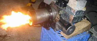
Another feature of mining as a fuel is that it is very difficult to supply all the air necessary for its combustion under pressurization; a lot of it is required. Therefore, by pressurizing in burners of this type, fuel is mainly drawn out from the ejector nozzle and atomized, and air for afterburning is sucked directly into the flame. This scheme makes it possible to use electric power of up to 100 W for supercharging, and the rest is spent on heating the fuel with a heating element. In general, the idea is this: we use part of the electrical power (with a significant increase, by the way) necessary for pressurization with more fluid fuel to heat the waste, and a generally conventional ejection burner works on it.
Diagram of the ejection burner during testing and drawings of the nozzle for it
A well-known diagram of the design of an ejection burner during testing and drawings of its heart - the nozzle for approx. 3-30 kW are given in Fig. Such a burner is installed on a blind flange in the combustion opening of the furnace/boiler, and secondary air is sucked into the torch through the ash pan. However, in addition to the nozzle, there are still subtle points in this design.
Turbulizer
The first of them is an air flow turbulator (swirler in the diagram in the figure above). Pressurization of the ejector burner during processing can be provided by a built-in volute fan or, through a gearbox, by the pneumatic system of the enterprise or by an industrial (possibly domestic of a similar design) piston compressor. For a burner power of about 3-15 kW, boost from a refrigeration compressor of 250 W electric is also possible.
Depending on the method of pressurization, the design of the turbulator changes. The compressor or compressed air distribution for driving pneumatic tools provides, under the conditions necessary for fuel ejection in the burner air jacket, an air flow that is too powerful and fast. The same is possible with a snail that is too powerful, for example taken from old trash. In this case, the turbulator should be an annular diaphragm around the nozzle with wide, slightly curved outer blades, pos. 1 and 2 in Fig. A pseudo-laminar jet of air from the diaphragm will pull the fuel out of the nozzle and ensure its stable ignition (see below), and 3-5 cm from the diaphragm, the burning oil mist will be picked up by a powerful whirlwind, atomized until it evaporates and is completely burned.
Design of the turbulator (swirler) of an ejection burner during testing, depending on the pressurization method
If the air flow is optimal (built-in volute by calculation) or weak (compressor from a refrigerator), then a turbulator made of many narrow, more curved internal blades is combined with the diaphragm, and an annular gap of 0.5-1.5 cm is left along the edge of the turbulator. Diaphragm - the swirler has less resistance to the air flow, a weak but immediately well-twisted vortex effectively sucks out and sprays the fuel, and the annular flow from the gap prevents the vortex from spreading to the sides until the fuel evaporates in the torch.
Note: the appropriateness of one or another turbulator for a particular burner is determined by experience - fuel ignition should be stable, and there should be no flameouts throughout the entire burner power adjustment range. You need to start with the diaphragm with the outer blades, bending them more and more. If it doesn’t work out, you need to switch to a turbulator diaphragm with internal blades.
Ignition
The second subtlety is igniting the torch. An auto candle with a removed “foot” (body lamella) is not very suitable, because designed to ignite light fuel vapor with a short spark, and not heavy fog with a long spark.
Method of igniting the fuel of an ejection burner during production using two electrodes
The burner torch must be ignited during production using electrodes for igniting liquid fuel boilers, see fig. The distance between the dischargers (spouts, points) of the electrodes is required to be 3-8 mm (for burners 3-30 kW), and the distance from the bare metal parts of the electrodes to the nearest metal parts of the structure must be at least three times greater. Turning on the nozzle: at the moment of ignition, the spark gaps must be in the oil mist emitted by the nozzle and ignite it with a spark among themselves. Ignition with a spark from a spark gap to the injector will produce a weak, unstable flame that can easily be disrupted by fluctuations in boost or fuel supply.
To ignite with two spark gaps, a special ignition transformer with an insulated secondary winding of 6-8 kV is required. Its terminals are connected to the ignition electrodes with wires in thick, from 2 mm, heat-resistant insulation made of silicone or Teflon (fluoroplastic). The latter is better: when heated to 150 degrees, the penetration resistance of fluoroplastic-4 remains approx. 80 kV per 1 mm, and silicone will not exceed 20 kV/mm. Such a huge margin of electrical strength is necessary due to severe contamination of the wires during operation.
A special ignition transformer is expensive because... These are produced for boilers from 20 kW. If the burner power is up to 15 kW (and for the Babington burner described below), you can use a single-wire ignition circuit from a car ignition coil with a spark from the electrode to the nozzle; This means the presence of only one high-voltage wire. The condition is manual switching to the mode: the burner is lit at minimum power and manually brought to the standard setting, making sure that the torch does not clog in convulsions or break.
To ignite the burner during testing using a single-wire circuit, the body terminal of the transformer is connected to the burner body and the nozzle with different return wires. The spark is not a direct current, but a pulsed discharge, and the electrical circuit becomes sensitive to the presence of reactivity in it. The electrical reactivity of the massive burner body is greater than that of the nozzle, which already makes it easier for the spark to choose the nozzle. If you additionally include a small inductance in the body return wire (see figure), then single-wire ignition will become quite stable.
Burner ignition circuit for testing with one electrode
About automation
Burners for testing, the operating mode of which is set from a remote control (for example, the well-known NORTEC) are very expensive, but without automation there is no point in installing a homemade ejection burner for testing: even with a fixed power and filling with fuel from the same batch, it is necessary to regulate simultaneously to obtain a stable flame fuel heating and air supply. Therefore, homemade ejection burners during development (excluding samples, just to tinker with them) are made semi-automatic with manual power setting and the use of relatively inexpensive automation from heating boilers, see for example. video
Video: burner in operation with automation
Babington burner
Robert Babington himself, who patented his burner in 1979, admitted that, having despaired of coming up with a nozzle that would not become clogged from working out, he remembered one of Murphy’s laws, which states: “If the iron still doesn’t want to work, try making it it's the other way around." Babington tried blowing air through a thin layer of oil - it worked. The fog began to set in, and how to burn it is a known matter.
This technical solution was possible due to the fact that oil is a rheological liquid. Simply - superfluid. It is not only exotic helium II that is superfluid. There are plenty of rheological fluids all around us. Anyone who has forgotten an open jar of sunflower oil on the table will immediately understand.
The design of the Babington burner and the combustion chamber (afterburner) for it
The design of the Babington burner is shown on the left in the figure, and on the right is the design of the combustion chamber (afterburner) for it. The disadvantage of this burner is already visible here: to burn the waste by more than 95%, a 3-stage air supply is required (except for atomization), and partially heated. Although boost is still not required.
The Babington burner operates quite simply: fuel drips onto a spray head with a spherical surface, which ensures its uniform spreading. It drips in excess so that the air always has something to blow off. The oil thrown out by a jet of air from the nozzle in the head forms a mist, which is set on fire. The fuel film constantly creeps onto the nozzle due to the rheological properties of the oil. Excess fuel flows into the collection tank, from where the feed pump supplies it through the heater back to the supply tank (feeder). Often, instead of a float turning on the pump, the feeder is provided with the excess in the tank draining directly into the collection tank; In this case, the feed pump operates continuously. However, the Babington burner also has enough design nuances.
Is a full sphere necessary?
The power removed from one Babington burner nozzle is limited by the finite value of oil fluidity. Therefore, the heads of powerful Babington burners are literally riddled with pores. If no more than 5-7 kW is required from the burner, it is possible to use part of the spherical surface instead of a technologically complex full-spherical head.
Design of a Babington burner with a head in the form of part of a sphere
The design of a Babington burner with a partially spherical spray head is shown in Fig. (how to make one is described in detail and with photos here: diyworkplace.ru/14-diy-oil-burner.html). In addition to the availability of materials, it is good to learn how to adjust the fuel supply with this burner: a little more, the oil flows behind the blade of the head, stinks, burns, and clogs the spray chamber.
The sphere is still better
The spherical head in the Babington burner is also better because it saves fuel: in a burner with a partially spherical head, a good portion of the return burns until it is impossible to use. In the end, it turns out that there is still a quarter or more in the tank, but the burner does not start.
How to make a Babington burner spray head from inexpensive materials for a completely different purpose, widely available, is shown in the figure:
How to make a Babington burner spray head from scrap materials
The good thing about a curtain rod plug is that its cut surface is flat and even. Drilling a nozzle hole in such a head blank is not difficult on a conventional drilling machine. If it moves away from the pole of the sphere within 1-2 mm, it’s okay. The main thing is that the axes of the nozzle and the sphere will be parallel and the torch will shoot evenly. You can even increase the power of the burner by drilling 3-4 holes around the pole of the sphere no closer than 6 mm from each other in a triangle or square. All that remains is to decide - how to drill?
How to make a 0.25 hole with a 0.6 drill
The permissible limits for the diameter of the Babington burner nozzle are 0.1-0.5 mm. Less maximum power is removed from a narrow nozzle, but the range of its adjustment is expanded, which is carried out by changing the air pressure for spraying. The latter for a 0.1 mm nozzle can vary within 0.5-5 atm, for a 0.25 mm nozzle - 1-3 atm, and the pressure in front of a 0.5 mm nozzle must be kept within 2 (+/-)0, 2 atm, otherwise the flame either breaks or goes out. Babington recognized the nozzle diameter of 0.25 mm as optimal; narrower nozzles become clogged with dust from the air, which requires at least 2-stage cleaning.
But how to drill a hole with a diameter of 0.25 mm? You can’t buy drills like this everywhere, and the machine needs high precision, otherwise the drill will immediately break.
The way out is to make a nozzle from part of a needle from a medical syringe. The channel diameters of syringe needles are 0.2-1 cubic meters. cm are just within optimal limits, and their outer diameter is 0.4-0.6 mm. These drills are widely available, and they can be inserted into a regular tabletop drill. Making a Babington burner nozzle from a medical needle is done as follows. way:
- Cut a piece from the needle 2-3 mm longer than the thickness of the head wall.
- We use a thin, stiff wire to remove sawdust and burrs.
- Using a drill slightly larger than the outer diameter of the needle, we drill a pioneer channel in the head. If you use a 0.6 drill to drill a channel for a 0.4 needle from the outside, it’s okay.
- Using a drill with a diameter 0.15-0.2 mm larger than the pioneer one, we countersink the hole on both sides. The chamfer needs to be removed tiny, so we countersink by hand, wrapping the drill shank with electrical tape and turning it with your fingers.
- We insert a piece of needle into the pioneer hole.
- Using two sharp awls or, better yet, metalworker's scribers, we unfold the ends of the needle segment. You need to unfold it at the same time, pressing lightly and turning the tools in opposite directions.
- We leave the bell inside as is, it does not interfere with anything.
- We remove the external excess using an emery stone no rougher than No. 360.
- Once again we clean the nozzle channel, blow it out - the head is ready.
What if the head is already ready?
A very possible option. If you take a ready-made diesel fuel nozzle onto the head; A defective one made from junk or cheap will do. Fans are confused by the fact that they are produced with a power of 20 kW, but in this case there is nothing to be afraid of, because It is not diesel fuel that will flow into the nozzle, but air. But its working surface is precisely hemispherical, mirror-smooth, with a collar that prevents the oil from flowing where it shouldn’t and burning. The nozzle, however, will be from 0.7 mm, but it can be narrowed as described above. How to make a Babington burner head from a diesel injector, suitable for long-term intensive use, and even with automation from a water heating boiler, see the story
Video: Babington burner with automation
Compressor for atomization
Atomizing air in a Babington burner requires a little air, but under decent pressure. A compressor from an old refrigerator is best suited for this purpose, but you need to put a car air filter in front of it, otherwise the vacuum pump will quickly fail. You also need a receiver, because... Such a compressor will produce a highly pulsating jet.
How to adapt a compressor from a refrigerator to supply air to a Babington burner during mining
The great advantage of such a system is the ability to automate burner ignition without electronics. For this we use a safety valve (see figure), because The refrigeration compressor builds up pressure to more than 5 atm. Let's take the worst valve, a disc valve with a flat seat (the disc and seat will need to be ground together with abrasive No. 600 or finer and washed with alcohol). Such valves have a large hysteresis (the ratio of opening and closing pressures), but in this case that’s what we need. We will also increase the hysteresis of the valve by placing a weight on its stem. When the compressor pumps the receiver to the initial response pressure, the valve will “puff” sharply, jump up and close the microswitch that supplies power to the ignition transformer for 1-2 seconds. The oil consumption will go up for combustion, the air flow will increase (it is more difficult to blow through a cold oil film), and the valve will begin to work part-time, not reaching the mic. The adjusting nut is convenient for changing the air pressure to change the burner power.
Compressor lubrication
In a refrigerator, the compressor is lubricated with refrigerant, because It pumps out freon mist from the evaporator rather than pure steam. Suddenly the compressor starts to sputter, which means that there is too much refrigerant and it circulates in the system in a droplet-liquid state. If you force a refrigeration compressor to pump air, it will soon deteriorate without lubrication.
You can lubricate the refrigerator compressor with a spindle or other machine oil for precision mechanics. First you need to make a lubricant dispenser, from a 50-100 ml tank, a needle from a regular syringe for 2-10 cc, a tube from a blood transfusion machine and a pair of clamps from the same. The upper one shuts off the lubricant supply, and the lower one regulates its amount.
The dispenser is adjusted in free space. It is necessary to ensure that a drop of lubricating oil accumulates on the tip of the needle, pointing straight down, for 2-4 minutes, and hangs for the same amount of time until it comes off. Then the needle is inserted perpendicularly into the compressor supply air duct so that its bevel is in the middle of the lumen and oriented along the flow. If the needle is turned sideways or against the air, the oil will not flow.
The system is ready for use, but you will still need to monitor it during operation. Suddenly, some time after starting the burner, the combustion character changes, which means that a lot of oil goes into the compressor and it drives the excess with air. If at least 10 minutes have passed before this, and the flame remains, just begins to pulsate or smoke, you can correct the matter by slightly turning the needle, no more than 45 degrees. If it doesn’t help or symptoms appear earlier, you need to reconfigure the lubricant dispenser for a longer drop accumulation time.
Flame down the chimney!
You can do an interesting experiment with a burner during testing, the results of which are visible in the trace. rice.:
Using a burner during mining to heat rooms
Having passed the burner flame through just 1 m of a wide pipe, we will see it no longer so furious and much cooled down (pos. 1), and a powerful flow of heated air will be noticeable from the pipe up. If you take a pipe with a diameter of 200 mm and a length of 3 m (item 2), then the temperature of the gases at its outlet will drop to less than 100 degrees. Let's expose the mouth of the pipe to the outside - the oily stench in the room will no longer be felt, although the gas analyzer will show that the impurities exceed the housing norm. All that remains is to hermetically connect the mouth of the pipe to the chimney, and we will get a heating system with an efficiency of more than 80%.
Evaporative
The waste can be burned without pressurization or heating at all, by dropping it drop by drop into a hot bowl. But such devices, as mentioned above, work more or less decently only as part of a boiler or furnace during mining, so they are not burners in the proper sense and are discussed in other publications.
Evaporative fuel-air (cup) burners in production
A fuel-air mixture is supplied to the bowl of the evaporation burner during exhaustion, i.e. a small boost is required (fan from 20 W). The bowl is preheated either with a gas torch (item 1 in the figure), or with regular fuel supplied dropwise (not yet pressurized), ignited by a glow plug (item 2). The latter is easier, but during the first 3-5 minutes there will be a lot of soot. When the flame from the next drop is cleared and begins to rise with noise, the candle is turned off and air is allowed in. Blue tongues will appear in the bowl (positions 3 and 4), indicating complete combustion of the oil, but impurities in it will transform into a chemically more aggressive form and go into the air, so you need to use evaporation burners during processing carefully, see above. The evaporation burner is not critical to the size of the parts; base – 1/2″ and 2″ water pipes.
Note: for temporary start-up of, for example, a garage potbelly stove, it would be more convenient to use an evaporative burner that operates on the same principle, but into which the fuel-air mixture is supplied tangentially from the side, see the video below:
Video: evaporation burner in production for a furnace
Parameters for making a soldering torch
Firstly, the device must be made of refractory metals. With a properly configured burner, you can get temperatures above 1000°C. Secondly, the burner must be equipped with a reliable working valve, which will shut off the gas supply in case of a dangerous situation. Thirdly, you need to use a reliable connection point to a can with a valve or a 5-liter propane cylinder with a reducer, which will eliminate the risk of accidents.
READ How to decorate a floor-standing gas boiler in the kitchen
Below is a typical diagram and principle of operation of an injection gas burner:
Fuel supply
Amateur craftsmen often supply drip furnaces with single-stage fuel: an oil tank, a ball valve, and a supply tube. Firstly, this is dangerous: for convenience and safety of starting the stove, the valve must be placed closer to it. The supply tube gets quite hot when fuel is supplied from the bottom. If the heating passes through the pipe past the valve, up to which there is a solid column of fuel in the pipe, this could lead to disaster. Secondly, the fuel supply to the furnace is unstable: as the tube warms up, the drops become more frequent, because the oil thins out. If it flows in a trickle, then it is again dangerous.
The drip supply of oil to the furnace during processing should be organized according to a 2-stage scheme: main (storage) oil tank - valve - supply dropper - supply tank (tank) - free flow from it at least 60 mm from the bottom (for additional sedimentation of sludge) - working dropper. The fuel supply is opened when the kindling in the bowl (see below) is lit. While the oil drips into the tank to the level of the drain, you can slowly adjust its flow, and then it drips into the bowl drop by drop.
Scheme of safe power supply of a drip furnace from a supply tank with a safety valve and capillary
This system, however, is not completely safe. If in a hurry, out of ignorance, or simply trying to quickly warm up from the cold, open the valve too much, the consumables will immediately fill, fuel will rush into the stove, and it will throw out a tongue of fire and start spitting burning spray. It would be correct to build a drip oil supply system into the furnace with a safety float valve and a metering capillary (see figure on the right).
Since different metals are wetted by waste in different ways, and its properties vary significantly from batch to batch, the length of the capillary will need to be selected: the oil is fed under a gravitational pressure of 120-150 mm (from a suspended container) at room temperature, and the capillary is selected so that it drips more often, but with drops clearly visible to the eye. A diesel fuel drip furnace can be used from the same feeder, but the capillary will need to be taken with a clearance of 0.6-1 mm and a length 2.5-3 times longer than for mining. There is only one drawback to this scheme for supplying fuel to a drip furnace: the exhaust is dirty fuel, and the capillary will have to be cleaned periodically.
DIY gas burner: manufacturing instructions
In this article we will look at how to make a gas torch for soldering with your own hands. This device is often in demand both in private households and for commercial purposes - for individual technical creativity and various types of construction tasks. In particular, gas burners are used for soldering, metalsmithing, forging, roofing, jewelry work, and for other purposes they produce flames whose temperature exceeds 1500°C.
In metalworking, using a gas torch, you can heat a metal workpiece so that in the end it turns out to be sufficiently hardened. When carrying out welding work with some metals, the areas of future seams must be heated.
How to improve flame control
For the normal operation of our homemade unit, we will install a divider and a tap on it. It is better to mount the faucet near the handle, at a distance of about 2–4 Washing machine, but it can also be attached to the supply pipe. As an option, take a burner tap from an old autogen or another similar tap that is attached with a thread. To seal the connection, take FUM tape.
The divider is installed on a pipe with a nozzle; it is made of brass, diameter 15 mm. The best option is a cylindrical part with a hole for a tube with a nozzle. If there is none, we do this: 1. Take a brass pipe with a diameter of 35 mm and cut a piece of 100–150 mm.2. Take a marker, step back from the end and mark 3-5 points, with an equal distance between them.3. We drill 8–10 mm holes in the pipe, take a grinder and make straight cuts to them.4. We bend everything to the center and weld it to the burner pipe.
Choosing a nozzle for bottled gas
As already mentioned, the propane nozzle has a shortened body and a smaller outlet diameter. It is not recommended to try to reduce the hole yourself, since even fractions of millimeters are important here. By eye you can only improve the operation of the stove, but not achieve its ideal operation.
It is important to understand that standard jets simply do not exist. They are designed for each specific model
Modern kitchen stoves are equipped with a set of jets designed to operate on propane. Some models are even produced specifically for bottled gas.
Heat exchanger for pyrolysis boiler
The best configuration for the heat exchanger of a homemade pyrolysis boiler will be the water jacket of the lower chamber and the chimney duct. This is not the most efficient type, however, producing your own honeycomb heat exchanger will cause inevitable difficulties either with finding pipes of the appropriate grade of steel, or with welding dissimilar parts.
The assembly of the heat exchanger parts is carried out at the stage when the bottom, front panel and two side walls of the boiler are welded. Access for welding work is provided from the rear of the boiler. The first step is to install the upper partition of the shirt. This is a rectangular plate along the internal width of the firebox and is 200 mm less than the depth of the combustion chamber. On the sides of the slab, two rectangular fragments 100 mm wide must be removed so that two protrusions 200 mm long remain in the front part of the slab. The resulting part is welded to the walls and front panel flush with the lower edge of the combustion chamber door opening. In this case, the cutouts in the partition form channels for circulation between the lower zone and the side walls of the heat exchanger.
The inner walls of the jacket are made along the edge of the flow channels, have the height of the combustion chamber and are adjacent closely to the front panel. They are covered on top with two strips 100 mm wide.
The length of the heat exchanger does not reach the rear wall of the boiler by about 200 mm, and the side channels protrude beyond the L-shaped partition between the chambers by approximately the same distance. When it is installed, all that remains is to form double walls of the chimney duct, cut out its outlet, secure the back wall of the boiler and cut in threaded fittings for connection to the heating pipeline. The return is inserted into one of the front lower corners of the jacket; the supply is inserted at any highest point of the chimney jacket.
Please note that the combustion chamber is limited on all sides by a water jacket, except for the partition with the gasification chamber. This is necessary for the transfer of heat, which ensures thermal decomposition of the fuel. In this case, not the entire filling will be heated at once, but only its layers adjacent to the heated walls.
Design of a homemade gas burner
- metal case;
- gearbox;
- nozzle;
- fuel supply regulator;
- head;
- a unit for securing a gas cylinder.
The metal case includes a special glass, with the help of which the mechanism eliminates the possibility of blowing out the flame. This also includes a metal or other handle that does not exceed 100 centimeters. A wooden holder and gas hose are installed on top of the handle. Using a reducer and a tube with a valve, the gas supply level and its length are adjusted accordingly. The nozzle is used to ignite the fuel, in this case the latter is propane.
Maintenance
Recommended:
- Use a brush to remove insects that accumulate inside the tube.
- Replace the flexible tubing periodically, checking the expiration date printed on it.
- Clean the burner openings periodically with a stiff brush.
- Use this device only outdoors.
- Do not move the device while it is running.
- Close the gas valve on the cylinder after use.
- Do not adjust or damage parts sealed by the manufacturer.
Attention. Before connecting the cylinder: Place away from any open flame and use outdoors or in well-ventilated areas - Make sure the gas valve is well closed by turning it clockwise. Place on a flat, non-flammable surface.
Modernization of heating equipment
Any home craftsman can install a homemade atmospheric gas burner for a sauna stove. So, without any special costs, a solid fuel boiler can be converted into a gas boiler .
Equipping an existing solid fuel stove in a sauna with a factory-made gas burner unit will require some adjustment. You will be faced with the need to modify the dimensions of both the burner and the combustion chamber of the wood-burning stove.
Converting a solid fuel sauna stove into a combined gas and wood stove is within your power, but it will require precision and some effort. Do not allow the flame to come into contact with the walls of the firebox
To heat the combustion chamber evenly, the burner should be positioned closer to the bottom of the stove and strictly in the center. It is unacceptable to place the source high and offset in any direction. In this case, the camera will not warm up completely. And the flame from the burner can touch metal parts or the heater of the sauna stove.
Atmospheric burners
A burner of this type sucks in air according to the principle of a jet pump: gas is passed through an ejector, where, due to the high speed of movement, its pressure drops (Bernoulli’s law); air is sucked into the gas flow due to the pressure difference. The strengths of this device include the following:
- Simplicity of design.
- Compactness.
- Energy independence.
- Low noise level.
- Low cost.
- Possibility of simple conversion of a solid fuel boiler to use gas fuel: the atmospheric burner just needs to be installed in the ash pan chamber.
The principle of operation of an atmospheric burner
However, it is impossible to “load” too much air into the gas flow only due to the jet effect, therefore burners with high power cannot be atmospheric.
The power limit for atmospheric burners is on average 9 kW (approximate value of the maximum heated area is 90 sq. m).
How to choose?
What you need to pay attention to when choosing a burner device for a boiler:
— productive power — noise level during operation (applies to supercharged models) — type of heating equipment for which the burner — type of fuel — pros and cons of this device — provide for possible malfunctions in the operation of the local gas supply mowing line.
Taking these factors into account, you can choose the most suitable burner device for your boiler so that it operates as efficiently as possible without the burden of frequent preventative maintenance.
Supercharged
This option uses a fan that actively pumps air. Stabilization of air pressure (pressure) allows you to compensate for almost all negative external factors
What is important is that “fire separation”, which often occurs with atmospheric burners with a significant increase in pressure, is also excluded
The following evidence supports such devices:
- stable operation under any conditions;
- efficiency of 95% or more;
- a fairly high level of safety (determined by the design);
- almost complete combustion of fuel;
- wide range of achieved powers;
- excellent level of automation;
- Possibility of use in furnaces and boilers of a wide variety of structural types.
It is worth noting that forced-air burners are much more expensive than their atmospheric counterparts. Even the most affordable models of this kind cost at least 4.5 times more. However, the main technical advantages fully justify such a fee. When the burner is operating with supercharging, noise of varying volumes may occur. Special protective covers will help to cope with this problem.
Such models are approximately twice as efficient as traditional flare designs. Some people even take tourist-type ceramic burners (for cylinders) and convert them into a boiler or stove. But you can do this only with complete confidence in your actions.
Gas mini burner
Mini gas burners are more suitable for working with small parts. The mini burner is based on a needle for inflating balls. It is necessary to make a cut in it, a little further than the middle of the needle. Some needles already have a similar hole, which significantly speeds up the work process. Next, you need to take the syringe needle and bend it about 45 degrees in the middle.
Mini gas burner design
It is best to sharpen the pointed end of a syringe needle so that it is straight. After this, it needs to be inserted into the ball needle so that one end comes out through the hole, and the other protrudes from the large needle by several mm. The resulting mini structure should be fixed using soldering. After this, droppers must be attached to the bases of the two needles. Clamps - dropper regulators need to be moved as close to the needles as possible. In the resulting burner they will act as gas and air supply regulators. They also need to be fastened together, and this is best done using a heat gun. All that remains is to connect a source of compressed gas to the finished device, the burner is ready for use. This homemade gas burner can heat objects up to 1000 degrees
You should work with it carefully, observing safety precautions
Why and why is it necessary to change the jet?
Jets for different types of gas vary significantly, so when changing the type of gas-air mixture, replacing the nozzles is simply necessary
If you pay attention to the diameter of the hole, it becomes obvious that they are not the same. In this case, the diameter of the hole depends not only on the type of gas used, but also on the size of the burner itself
Some time after replacement, negative factors may appear indicating that the stove is not working properly. Don’t rush to change the jet right away; you may be able to limit yourself to cleaning it
Each of the gas stove burners differs in power and size, so for stable operation it is equipped with a separate nozzle.
The diameter of the outlet of each nozzle is calculated for a certain volume of gas supplied from the main line or gas tank
The more powerful the burner, the greater the volume of gas it requires to operate, therefore the diameter of the nozzle is required to be larger.
Sources:
https://morflot.su/gazovaja-gorelka-na-prirodnom-gaze-svoimi-rukami/ https://www.umeltsi.ru/prisposoblenia/5139-gazovaya-gorelka-svoimi-rukami-chertezhi-instrukciya-po- izgotovleniyu.html https://1-teplodom.ru/gazovaa-gorelka-dla-peci-kak-sdelat-forsunku-svoimi-rukami/
Which burner is suitable for a cauldron?
To cook food in a cauldron, you need a fairly powerful and spacious burner. It is best to use a model with a hose. The design of such a device allows you to install a fairly large container. When selecting a burner for a cauldron, you should consider:
- Power. The larger the size of the cooking utensils, the higher the power rating of the equipment should be.
- Material. Cast iron burners are considered the most durable. They do not deform at high temperatures and exposure to heavy dishes.
- Design. The cauldron has a fairly wide bottom, so when choosing a gas burner you should take its size into account.
- Legs. An important aspect of choosing a burner for a cauldron is the presence of stable supports. The legs should be strong and set wide.
Reference. Convenient use of the burner is ensured by piezo ignition and power adjustment. With the help of a properly selected device, you can cook any dish in a cauldron while relaxing in nature.