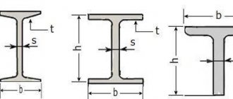
Published on Sep 21, 2014 Category: Mechanics |
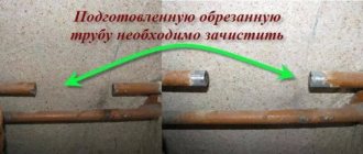
When designing and manufacturing bent parts from pipes and rods, the task of determining the length of the development - the length of a straight workpiece before the start of the bending process - always arises.
Continuing the topic...
...calculating the length of the development of parts bent from sheet metal of rectangular section, I present the calculation in Excel of the length of the development of parts made of rods and pipes of round cross-section.
The calculation program is written according to the classic strength of strength formula! Practical results will differ slightly from calculated values due to a number of factors, which were already mentioned in the article on sheet metal bending (link to this article in the previous paragraph). However, the program presented below will ensure accuracy when bending a pipe for the manufacture of a prototype.
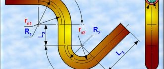
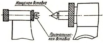
Below this text the figure shows the calculation diagram.
The radii of the neutral layers of each of the curved sections are calculated using the formula:
rni =((4* Ri 2 - D 2 )0.5+(4* Ri 2 - d 2 )0.5)/4
The neutral layer is the surface closer to which, closer to the center of the bending radius, the pipe material is compressed during bending, and further from the center of the bending radius, it is stretched.
The length of curved sections when bending a pipe is determined by the formula:
li=π*αi/180*rni
Here the angle αi must be in degrees.
The total length of the development is calculated by summing the lengths of straight and curved sections:
L = ∑( Li + li )
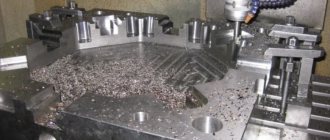
Calculation of workpiece dimensions during bending
Let's consider a situation that often arises in bending production.
This is especially true for small workshops that make do with small and medium-sized mechanization. By small and medium mechanization I mean the use of manual or semi-automatic sheet benders. The operator sums up the length of the shelves, obtains the total length of the workpiece for the required product, measures the required length, cuts and... after bending, receives an inaccurate product. Errors in the dimensions of the final product can be quite significant (depending on the complexity of the product, the number of bends, etc.). This is because when calculating the length of the workpiece, it is necessary to take into account the thickness of the metal, the bending radius, and the coefficient of the position of the neutral line (K-factor). This is exactly what this article will focus on. To be honest, calculating the dimensions of the workpiece is not difficult. You just need to understand that you need to take into account not only the lengths of the shelves (straight sections), but also the lengths of the curved sections resulting from plastic deformations of the material during bending.
Moreover, all the formulas have long been derived by “smart people”, whose books and resources I constantly indicate at the end of the articles (from there, if you wish, you can get additional information).
Thus, in order to calculate the correct length of the workpiece (part development), which ensures the required dimensions after bending, it is necessary, first of all, to understand which option we will use to make the calculation.
| Option 1 | Option 2 |
| Lt = A + B + BA | Lt = A + B – B D |
| Lt – total length of the flat workpiece; A and B – see picture; VA - allowance | Lt – total length of the flat workpiece; A and B – see picture; B D – deduction |
Thus, if you need the surface of shelf A without deformations (for example, for the location of holes), then you calculate according to option 1 . If the overall height of shelf A , then, without a doubt, option 2 is more suitable.
Option 1 (with allowance)
a) Determine the K-factor (see Reference);
b) Divide the contour of the bending part into elements, which are straight segments and parts of circles;
c) Sum up the lengths of these segments. In this case, the lengths of straight sections are summed up without change, and the lengths of curved sections are summed up taking into account the deformation of the material and the corresponding displacement of the neutral layer.
So, for example, for a workpiece with one bend, the formula will look like this:
Where X 1 is the length of the first straight section, Y 1 is the length of the second straight section, φ is the external angle, r is the internal bending radius, k is the neutral line position coefficient (K-factor), S is the metal thickness.
Moreover, we will have to count the length of each shelf separately before setting the point of movement of the rear stop of the machine. I hope this is clear.
Thus, the calculation progress will be as follows..
Y1 + BA1 + X1 + BA2 + ..etc
The length of the formula depends on the number of variables.
Option 2 (with deduction)
In my experience, this is the most common calculation option for rotary beam bending machines. Therefore, let's look at this option.
We also need:
a) Determine the K-factor (see table).
b) Divide the contour of the bending part into elements, which are straight segments and parts of circles;
c) Calculate the required deductions. In this case, the lengths of straight sections are summed up without changing, and the lengths of deductions are subtracted accordingly.
Here it is necessary to consider a new concept - the outer boundary of bending.
To make it easier to imagine, see the picture:
The outer boundary of the bend is this imaginary dotted line.
So, to find the length of the deduction, you need to subtract the length of the curved section from the length of the outer boundary.
Thus, the formula for the length of the workpiece according to option 2:
Where Y 2 , X 2 – flanges, φ – external angle, r – internal bending radius, k – neutral line position coefficient (K-factor), S – metal thickness.
Our deduction ( BD ), as you understand:
Outer bending limit ( OS ):
And in this case, it is also necessary to calculate each operation sequentially. After all, the exact length of each shelf is important to us.
The calculation scheme is as follows:
(Y2 – BD1 / 2) + (X2 – (BD1 / 2 + BD2 / 2)) + (M2 – (BD2 / 2 + BD3 /2)) + .. etc.
Graphically it will look like this:
And yet, the amount of deduction ( BD ) must be calculated correctly when calculating sequentially. That is, we are not just cutting two. First we count the entire BD , and only after that we divide the resulting result in half.
I hope that I did not offend anyone with this remark. I just know that mathematics is forgotten and even basic calculations can be fraught with surprises that no one needs.
Source
How to correctly calculate the dimensions of the shell (schuber) layout?
Typically, the work of preparing or finalizing original layouts for various types of packaging is undertaken by our pre-press department. But there are times when customers or designers want to independently compose a layout for printing and ask us: “How to correctly calculate the dimensions of the shell/sleeve so that the contents fit into the cardboard package and do not fall out of it?”
Let's take a closer look at what this popular type of packaging is and what needs to be taken into account when calculating the layout dimensions.
Basic packaging requirements
What a shell is and how it differs from a shuber is discussed in detail on the page “SHUERS AND WELLS” >>
The shell (popularly known as “shuber”) should be:
Let's talk about the last two points. The matter is, in general, simple, but there are nuances.
How to calculate the dimensions of a rectangular shell layout
The simplest design is a rectangular (unfolded) shell.
She has three characteristics:
Calculation of shell length
1. Determine the sum of the lengths of all surfaces
Take the box on which you are going to put the future shell, and measure the length of all surfaces that the packaging will “hug”. Take measurements at right angles to the edges. Let's sum up all the values.
2. Increase for loose fit
3. Valve for gluing
The standard valve size is 12-18 mm.
Sometimes, instead of gluing, a self-assembling lock is used, which snaps into place at the place where the product is packaged. The lock takes about 30 mm over the entire length, this should also be taken into account.
We sum up the values from three points and get the length of the shell:
Shell length = sum of lengths of all surfaces + increase + valve
Shell width
Width is that part of the product packaging that the shuber will close. Here it’s up to you to decide whether to cover the entire package or make the cardboard shell narrower so that the product is visible.
Shell thickness
This is the thickness of the cardboard plus lamination, if any.
When making preliminary calculations, the thickness of the cardboard can be ignored; let the printing house figure it out