As a rule, entire design bureaus prepare projects, after which the drawings are transferred to assembly areas for manufacturing. To avoid discrepancies in their reading, there are special standards called GOSTs. They give clear recommendations on how to put down dimensions correctly and what symbols can be used to indicate certain elements.
General rules for drawing up drawings of metal structures
Marking of structural elements .
Elements of metal structures are indicated in the drawings with marks. For marking elements of the main types of metal structures, the letter designations given in table are proposed. 12.3.1. Non-standard products, in the design of which there are differences that do not affect their main characteristics, are designated by the same brands as the products in the basic design, but with the addition of indices (for example, B1a, B16).
Elements of the same cross-section are designated by the same brand. The same grade is assigned to these elements even if they have different lengths, but the design forces are close in value. Standard products (structural elements) are designated by marks taken from the relevant standards, drawings of standard products and catalogs.
If elements have different cross-sections, they are assigned different brands.
The symbols of the brands of the main elements of metal structures are made up of capital letters (determining the type, structure) and numbers (the serial number of the element).
The designation of the serial number is accepted for each type of element separately, for example, F1, F2 or B1, B2, BZ.
Small structural elements, connections, beams of small areas, wall frame crossbars are marked within the same diagram in lowercase letters. If the letters of the alphabet are not enough for marking, it is continued with double letters or combinations of letters and numbers. If elements with the same marks are continuously repeated along the entire length of the plan or section, it is allowed to indicate their markings only in the extreme sections and at expansion joints.
The scale of the drawing is chosen depending on the complexity of the design and the structure as a whole, so that the compactness of the image, ease of use of the drawing and obtaining clear copies with modern methods of reproduction of drawings are ensured.
When making drawings of elements (braces, racks, truss chords, etc.) having a length significantly greater than the transverse dimensions, it is allowed to depict these elements in the transverse direction on a larger scale (usually twice as large).
Lines . When schematically depicting metal structures in one line and for drawing a visible contour in detailed images, the use of a solid main line is allowed. When schematically and semi-schematically depicting the contours of structures, elements made of other materials are depicted with a thinner solid line.
The arrangement of types of elements of metal structures is somewhat different from the arrangement of types of wooden and reinforced concrete structures. Views on drawings of metal structures are usually arranged as follows (Fig. 12.3.1). The top view in the projection connection is above the main view, the bottom view is below the main view, the right view is to the right of the main view, the left view is to the left of the main view. Above each view (except for the main one) an inscription of type “A” is made, and the direction of view is indicated by an arrow indicated by the corresponding letter. This arrangement of individual images (views) is obtained by projection using the third angle method (method A).
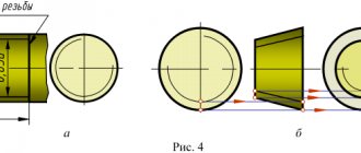
If you need to show some part of the structure, then on the main or some other view the direction of view can be shown as a section or section (with two open strokes with arrows), and the image itself can be accompanied by the inscription: 1-1 or 2-2, etc. .p., and the image can be located anywhere on the sheet. Metal structures in the drawings can be depicted schematically, simplified and in detail (Fig. 12.3.2, a-c). If it is necessary to show any part or assembly of a structure on a larger scale with a sufficient degree of detail, the enlarged image is placed next to the simplified drawing.
When depicting a structure in detail, all its visible parts and connections located in the immediate vicinity of the observer are drawn, and the invisible parts are drawn only those that are located close to the visible ones. Invisible elements separated from visible ones by an air gap are not shown in the drawing. To depict invisible parts of elements as visible, make a gap in the material, as in Fig. 12.3.2, c, which shows an unequal angle, invisible from above, welded to the vertical wall of the beam.
Metal structures made from rolled profiles can be shown in drawings without rounding the corners.
Sections, sections . The contours of structural elements in the images of sections and sections are not hatched. In drawings whose scale is smaller than 1:20, cross-sectional images of structural elements may be shown in one line. Holes, rivets and bolts in views and sections parallel to their axes can be represented by axial lines.
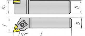
Slopes, slopes. Bevels in drawings of structural elements are indicated by linear dimensions (Fig. 12.3.3a) or using a right triangle, the hypotenuse of which coincides with the edge of the image or extension line (Fig. 12.3.3b). The size of the horizontal or vertical legs is the absolute or relative value of their length. The slope of an element of metal structures (for example, braces of a truss) is also indicated by a triangle, but it is placed in close proximity to it or on the continuation of the center line (Fig. 12.3.4).
Marking. If necessary, elements of metal structures are marked by placing the mark on the shelves (Fig. 12.3.5, a).
However, industry standards allow marking to be done in circles with a diameter of 5-7 mm. A wavy line runs from the element to be marked to the circle (Fig. 12.3.5, b).
Rules for marking steel pipes, how to read the designations
A competent specialist, based on the numbers printed on the surface of the pipe product, can name the main parameters of the pipes, material of manufacture, strength characteristics, as well as the manufacturer. Special purpose steel pipes have markings that differ slightly from the standard designations.
The following are called special purpose products:
- Alloy steel pipe products.
- Stainless steel pipes.
- Pipes for drilling.
- Pipe elements of main pipelines.
- Pipes for boiler rooms.
What can be used for marking?
For marking the following can be used:
- Indelible paint.
- Electrographs.
- Electric inkjet printing devices.
- Branding.
No data is applied to some types of pipe products, and for those that must have markings, the marking method is selected depending on the grade and main parameters of the pipe.
Standard marking of steel pipes
All necessary data is applied to the pipes according to a certain standard.
Location of symbols
Manual marking of a steel pipe is printed at a certain distance from the end of the product: no less than 2 cm and no further than 50 cm. With mechanized marking, this value increases and is 0.1 m and 1.5 m.
Symbol size
The letter and numerical designations of the pipe must have a certain size, which is also regulated by a certain regulatory document. Signs must have a height of no less than 0.5 cm and no more than 3 cm, and a width from 0.3 cm to 1.2 cm. The size of the signs is determined in accordance with the parameters of the pipe.
Division into classes
Conventionally, pipe products are divided into the following classes:
- Class 1 pipes can be used for gaseous and liquid media in irrigation systems. In addition, it is possible to manufacture fencing structures or supports from such products.
- Class 2 pipes can be used in pipelines operating at low and high pressure, transporting oil and petroleum products, gas or water.
- Class 3 pipes are suitable for work at high temperatures.
- Class 4 includes thick-walled drill pipes that can resist strong torsion.
- Class 5 pipes are used in the construction of carriages, cars, overhead cranes, drilling rigs and some furniture structures.
- Class 6 pipes are used in the engineering industry as blanks from which bearings, cylinders, pumps and receivers are produced.
As the thickness is indicated in the drawing
For registration of design documents, basic letter designations are provided that reflect the following conventional values:
- Center-to-center distance
- Width
- Diameter
- Height, depth
- Length
- Radius
- Thickness (sheets, walls, ribs, etc.)
- Step
- Angles
It is recommended to use capital letters to indicate overall and total dimensions.
If the same letters are used in the same document for different quantities, numerical or alphabetic indices are used, for example:
Based on the images of an object in the drawing, one can judge its size and the size of its individual parts. The basis for this are dimensional numbers, regardless of what scale and with what accuracy
images are completed. The rules for applying dimensions on drawings are established by GOST 2.307-68.
Dimensions in the drawing are indicated by dimensional numbers, dimension and extension lines. Dimensional numbers on drawings are usually indicated in millimeters without indicating units of measurement. In cases where it is necessary to use other length units, they are shown after the dimension number.
Dimensional numbers are applied above the dimension line, possibly closer to its middle. The gap between the size number and the size line should be about 1.0 mm. The height of the dimensional numbers is taken to be at least 3.5 mm (Fig. 7).
The dimension line is drawn parallel to the segment whose size is applied above it. It is carried out between extension lines drawn perpendicular to the dimensional ones. It is allowed to draw dimension lines directly to the lines of the visible contour, axial and center. In some cases, the dimension line may not be drawn perpendicular to the extension (Fig. 8).
Dimension lines are limited by arrows (Fig. 9). In some cases, they are not carried out completely, but with the arrow broken on one side (Fig. 10). The size of the arrow is chosen based on the thickness of the solid thick main line adopted in the drawing. Within one drawing, the size of the arrows should be the same as possible.
It is not recommended to use contour, axial, center and extension lines as dimension lines.
If the length of the dimension line is small to accommodate the arrows, then the dimension line is extended beyond the extension lines, and the dimensions are applied as shown in Fig. eleven.
Extension lines are drawn from the boundaries of measurements; they are auxiliary and serve to place dimension lines between them. If possible, extension lines should be placed outside the image contour, perpendicular to a straight line segment, the size of which must be specified. The extension lines should extend beyond the ends of the arrows of the dimension lines by 1.5 mm (Fig. 12).
The minimum distance from the dimension line to a line parallel to it should be 10 mm, and between parallel dimension lines - 7 mm.
Angular dimensions in drawings are indicated in degrees, minutes and seconds, indicating units of measurement. The size of the angle is applied above the dimension line, which is drawn in the form of an arc with the center at its apex. In this case, extension lines are drawn radially (Fig. 13).
With different inclinations of dimension lines, the dimensional numbers of linear dimensions are arranged as shown in Fig. 14, a, and the angular dimensions are as shown in Fig. 14, b.
If the dimension line is located in an area that is shaded in the drawing, dimension numbers are applied on the shelves of leader lines (Fig. 15).
If there is not enough space above the dimension line to write the dimension number or this space is occupied by other image elements and
It is impossible to enter a dimensional number into it; the dimensional number is applied according to one of the options shown in Fig. 16.
In order to simplify a number of images and create ease of reading of the drawing, the standard provides for the use of symbols in the form of letters of the Latin alphabet and graphic signs that are placed in front of the dimensional numbers. Used in drawings
signs and letters to indicate diameter and radius, arc and square length, slope and taper, sphere, thickness and length of the part.
The sign 0 is applied before the diameter size number (Fig. 17). Moreover, there are no gaps between the sign and the number. For circles of small diameter, the arrow dimension lines and the dimension itself are drawn according to one of the options shown in Fig. 18.
The dimensional number of the arc radius is always preceded by a sign in the form of a capital Latin letter R.
In this case, the dimension line is drawn towards the center of the arc and is limited to only one arrow, resting on the arc or its extension (Fig. 19). If the radius in the drawing is less than 6 mm, it is recommended to place the arrow
lay on the outside of the arc. If it is necessary to specify the position of the center of the arc, it is marked by the intersection of center or extension lines (Fig. 20). In cases where the drawing shows an arc of large radius, for which the center need not be marked, the dimension line is cut off without reaching the center (Fig. 21).
If in this case the center needs to be marked, it is allowed to bring it closer to the arc (Fig. 22). The dimension line in this case is shown with a 90° bend, and both sections of the dimension line are drawn parallel. Dimension lines that extend from the same center and are intended to indicate dimensional arcs should not be placed on the same straight line.
It is recommended to use radii to denote arcs up to 180°; arcs whose magnitude is more than 180° are designated by diameter.
The arc sign is applied above the dimension number (Fig. 23). The length of the arc is specified in linear units, and the dimension number indicating the arc is plotted above the dimension line in accordance with the usual requirements.
Read also: The principle of operation of a pirate metal detector
To set the dimensions of a square, use the corresponding sign D, the height of which is equal to 7/10 of the height of the dimension number (Fig. 24, a).
If the square is positioned differently, the dimensions of its sides are indicated (Fig. 24,
b).
It should be noted that the square sign is applied only on the image on which it is projected into a line.
The surface conicity sign is applied on the shelf of a leader line located parallel to the cone axis or on the cone axis (Fig. 25, a).
The cone sign is positioned so that its acute angle is directed towards the apex of the cone.
The amount of taper is determined by the ratio of the difference in diameters of two cross sections of the cone to the distance between these sections, i.e. k
=
D
-
dll,
where
D
is the diameter of the large section;
d
—diameter of the smaller section; / is the distance between sections.
Taper is indicated as a simple fractional number (Fig. 25, b).
The straight slope sign is indicated on the shelf of the leader line. Slope i
represents the tangent of the angle between a given line and a horizontal or vertical line (Fig. 26, a). The slope sign is located
so that its acute angle is directed towards the slope of the straight line (Fig. 26, b).
The slope, like the taper, is specified in the drawing as a simple fraction, as a percentage or in ppm.
https://www.youtube.com/watch?v=kv5C8zt3xEw
To designate a sphere in a drawing, use the sign of diameter or radius. In cases where it is difficult to distinguish a sphere from other surfaces in a drawing, the word “Sphere” may be added before the sign of the radius or diameter. The inscription on the drawing is made according to the type “Sphere diameter 17” or “Sphere R
10" (Fig. 27).
Simple flat parts are depicted in a single projection. In these cases, its thickness is denoted by the lowercase letter s
and the inscription on the drawing is made according to type
s2
and is located on the shelf of the leader line (Fig. 28, a).
The length of the object is indicated by the letter / (Fig. 28, b).
Chamfers in the drawings are applied in two linear dimensions (Fig. 29, a)
or one linear and one angular (Fig. 29,
b).
In the event that
the angle of inclination of the cone generatrix is 45°, a simplified chamfer designation is used when the dimension line is drawn parallel to the axis of the cone, and the inscription is made as “2 x 45” (Fig. 29, c).
SELF-TEST QUESTIONS
1. What classification groups of ESKD standards exist?
2. How many sheets of A4 format are contained in A1 format?
3. What are the rules for placing the title block on the format?
4. What is the content of the title block?
5. What scale do you know?
6. How are scales designated?
7. What is the thickness of center, center, extension and dimension lines?
8. What lines are used to outline the outline?
9. What determines font size?
10. How is the height of lowercase letters determined?
11. What signs are used when applying dimensions?
12. At what distance from each other and from the contour line are the dimension lines drawn?
13. When is the diameter sign 0, and when is the radius sign R?
14. Where on the drawing is the size of the number applied relative to the dimension line?
15. How does the scale of the image affect the size of the dimensions applied in the drawing?
16. What is a slope, as is it indicated on the drawing?
17. What is taper, how is it indicated in the drawing?
18. How are conical chamfers indicated in the drawing?
3.1. Main provisions of the standard
The basis for determining the size of the product and its elements are the dimensional numbers printed on the drawing. Dimensions are always true, regardless of the scale and with what accuracy the image is made. Dimensions must be assigned and applied so that they can be used to produce a part without resorting to calculations.
There should be a minimum number of sizes, but sufficient for the manufacture and control of the product. The absence of at least one of the dimensions makes the drawing practically unusable. Dimensions must be marked in such a way that no ambiguities or questions arise when reading them. It should be remembered that the drawing is read in the absence of the author.
According to GOST 2.307-2011 - “Applying dimensions and maximum deviations”, linear dimensions in the drawing are given in millimeters, without indicating the unit of measurement. Angular dimensions are indicated in degrees, minutes, seconds with the designation of the unit of measurement. Each dimension is indicated on the drawing, in the main inscription, only once; it is unacceptable to repeat it.
When indicating the dimensions of straight segments, dimension lines are drawn parallel to these segments at a distance of at least 10 mm from the contour line and 7 mm from each other, and extension lines are drawn perpendicular to the dimension lines.
Extension lines should extend beyond the ends of the arrows of the dimension line by 1...5 mm. The arrow of the dimension line must have a length of at least 2.5 mm and an apex angle of about 20° (Figure 3.1).
The dimensions and shape of the arrows must be the same throughout the drawing.
3.2. Applying dimensions
In the drawings of parts, dimensions are indicated based on the manufacturing technology of the part and the surfaces on which the part comes into contact with other parts of the assembly unit.
This affects the choice of design base.
Based is the process of giving the workpiece the required position relative to the selected coordinate system.
Read also: Uranium deposits in Russia
A base is a surface or combination of surfaces, an axis or a point belonging to a product or workpiece and used for basing.
Design base - a base used to determine the position of a part or assembly unit in a product.
The basic rule for applying dimensions is to group dimensions related to one geometric element in one image, in the one in which this element is most clearly represented. It is not always possible to achieve this, but we always strive for this.
When indicating the size of an angle, the dimension line is drawn in the form of an arc with the center at its vertex, and the extension lines are drawn radially (Figure 3.2).
| Figure 3.1 | Figure 3.2 |
It is preferable to apply dimension lines outside the outline of the image. The use of contour lines, axial, center and extension lines as dimension lines is not allowed. The intersection of dimension and extension lines, shown in the crossed out Figure 3.3, a, is unacceptable. The correct dimensions for this case are shown in Figure 3.3, b.
| A | b |
As you can see, smaller dimensions should be placed closer to the contour of the part; the number of intersections of dimension and extension lines will be reduced, which will make the drawing easier to read.
The dimension line is drawn with a break if it is not possible to draw an extension line on one side of the image, for example, in the case of combining a view and a section (Figure 3.4, a), and also if the view or section of a symmetrical object is depicted only to the axis or with a break (Figure 3.4, b). The break of the dimension line is made further than the axis or break line of the object.
| A | b |
Dimension lines may be drawn with breaks in the following cases:
- when indicating the size of the circle diameter; in this case, the break of the dimension line is made further than the center of the circle (Figure 3.5);
- when drawing dimensions from a base not shown in this drawing (Figure 3.6).
| Figure 3.5 | Figure 3.6 |
The main line must be broken if it intersects with the arrow (Figure 3.5).
When depicting a product with a gap, the dimension line is not interrupted (Figure 3.7). The dimensional number must correspond to the full length of the part.
Figure 3.7
If it is not possible to place dimensional numbers and arrows between closely spaced solid main or thin lines, they are applied outside (Figure 3.8). Do the same when applying the radius size if the arrow does not fit between the curve and the center of the radius (Figure 3.9).
| Figure 3.8 | Figure 3.9 |
It is allowed to replace arrows with dots or serifs, applied at an angle of 45° to the dimension lines, if it is impossible to place an arrow between the extension lines (Figure 3.10).
Figure 3.10
Dimensional numbers must not be divided or crossed by any drawing lines. At the place where the dimension number is applied, the axial, center lines or hatch lines are interrupted (Figure 3.11).
Figure 3.11
Dimension numbers should be placed above the dimension line, as close to its middle as possible (Figure 3.12).
Figure 3.12
Dimensional numbers of linear dimensions with different slopes of dimension lines are placed as shown in Figure 3.13.
If it is necessary to apply dimensions to the shaded area, the corresponding dimensional number is applied on the shelf of the line - leader.
Figure 3.13 Angular dimensions are applied as shown in Figure 3.14.
Figure 3.14
Unification and standardization
To make it easier to read drawings in the production process, there are special GOSTs (state standards). They are combined into a set of rules, which is referred to as a UNIFIED SYSTEM OF DESIGN DOCUMENTATION (USD).
GOST 2.321−84 establishes letter designations that are commonly used in design documents and assembly drawings used in various industrial sectors. The dimensions of products or parts and total dimensions are indicated in capital letters.
When designating different quantities in one drawing with the same letter, the use of indices or their combinations is allowed. Example designation: R, R1, R2, Dn, Dn1, Dn2.