- Fastening threads Cylindrical threads Metric threads
- Helix line. Basic thread parameters. Thread image
- Bolts
A thread is a surface formed by the screw movement of a flat contour along a cylindrical or conical surface. If a point makes a screw movement, then the spatial curve it produces is called a helical line (Fig. 1).
Image of thread on drawings
According to GOST 2.311-68, threads of all types are depicted conventionally.
On the rod
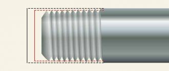
The thread on the rod is depicted by solid main lines (s) along the outer diameter and solid thin lines
In the hole
When making a cut, the thread in the hole is depicted with solid main lines along the internal diameter of the thread and solid thin lines along the outer diameter (Fig. 5). In the images obtained by projection onto a plane perpendicular to the axis of the hole, an arc is drawn along the outer diameter of the thread, approximately equal to 3/4 of the circle, open at any place.
The thread boundary in the hole is shown with a solid main line, drawing it to the lines of the outer diameter of the thread.
Hatching lines in sections and sections are drawn to the lines of the outer diameter of the thread on the rod and to the lines of the internal diameter in the hole, i.e. in both cases to the solid main lines.
In connection
On sections of a threaded connection, when depicted on a plane parallel to its axis, only that part of the thread that is not covered by the thread of the rod is shown in the hole (Fig. 6).
How to determine the pitch of an inch thread?
To understand whether the pitch size of inch cutting meets the requirements of GOST, you need to take measurements. You will need a template and tools. Any fitting can be used as a template, the step size of which exactly corresponds to the technical documentation. A bolt, the cutting pitch of which is measured, is screwed into the selected element. If the connection is tight, the notch pitch complies with GOST requirements.
You can determine the pitch of an inch thread using a thread gauge.
If the connection is loose or the bolt does not fit, the measurement is carried out with a thread gauge. The plate is tightly applied to the thread - a tight fit will indicate that the notches correspond to the size indicated on the body.
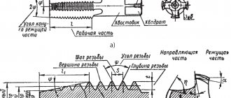
Basic thread parameters
- external (nominal) thread diameter d,D - the diameter of an imaginary cylinder or cone described around the tops of an external thread or the valleys of an internal thread;
- internal thread diameter - the diameter of an imaginary cylinder or cone described around the roots of an external thread or the tops of an internal thread;
- thread profile - the contour of a thread section with a plane passing through its axis: triangular, trapezoidal, rectangular, round (for example, in Fig. 2, triangular profile);
angle (thread profile angle) - the angle between adjacent sides of the profile;
- cylindrical thread pitch P - the distance between adjacent profile sides of the same name;
- cylindrical thread stroke - the distance by which the point moves in one full revolution; in a single-start thread, the stroke is equal to the pitch; in a multi-start thread, the product of the pitch P and the number of starts (Fig. 3);
- thread direction: right (clockwise rotation), left (counterclockwise); indicated in the thread designation with the letters LH;
- the surface on which the thread is cut - cylindrical or conical.
Cutting tools
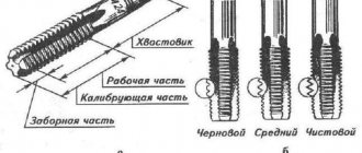
A tap is used to cut internal threads. This is a special screw that has hard cutting edges. This tool consists of a working part and a shank designed for fixation in the driver. The device can be manual or machine.
Locksmith kit contents:
- Tap. Its diameter can vary and reaches 18 mm.
- Two rough working parts.
- Rough tap of a different diameter, medium and finishing.
The product is marked in the same way as bolts. That is, it has a letter and number designation. But it also has risks that show its type (rough, medium, finishing).
Before you start cutting, you must first make a hole that will have a slightly smaller diameter. During operation, the tool must be held perpendicular and lubricant added to the cutting area. The tap should be unscrewed every few turns to remove accumulated metal shavings. This is very convenient to do with a small special brush.
On an industrial scale, external threads are made on a machine. For household needs, dies are used, which are:
- Split. The tool is made of two halves, which is why it is not as rigid as other types. Can be used for undemanding connections.
- Whole round. With this die you can cut high-quality threads.
- Sliding. Used in clamps. You can make pipe threads.
The die itself looks very similar to a regular nut, inside of which there are cutting edges. The tool can be designed for cutting metric or inch threads.
Classification of threads
- according to the shape of the surface on which the thread is cut (cylindrical, conical);
- according to the profile shape (triangular, rectangular, trapezoidal, round, etc.);
- in the direction of the helical surface (right and left);
- by the number of passes - the number of helical lines (single-start, multi-start);
- by the location of the thread on the surface of the rod or in the hole (external and internal);
- according to their intended purpose (fastening, fastening and sealing, running, special, etc.).
The fastening thread is intended for a fixed connection of parts. Metric and inch threads are used as fastening threads.
Fastening and sealing threads are mainly intended for tight, hermetically sealed connections of parts. These include pipe and tapered threads.
Running threads are used to transmit axial forces and movement in lead screws of lathes, lifting devices, etc. Trapezoidal, thrust, and rectangular threads are used as running threads. They can be single-pass or multi-pass.
Mounting threads
The most widespread are fasteners. Their purpose is to screw together and secure individual parts.
Straight threads
Cylindrical pipe thread is a detachable connection consisting of spiral grooves cut inside and outside of parts. This type of thread is used for the installation of pipes, fittings, shut-off and control valves, as well as other pipeline structural elements. The thread has a triangular cross-section with an apex angle of 55°.
Metric thread
Metric threads are standardized and have a triangular profile with an angle of 60° at the apex.
Starting from 6 mm, for each metric thread diameter there is one large pitch and several small ones.
The symbol for a metric thread with a large pitch includes the letter M and the nominal (outer) diameter of the thread in millimeters. For example, M 56 (Fig. 7) means that the thread is metric with a large pitch, with a nominal diameter of 56 mm (the pitch size is not indicated).
In the symbol for a metric thread with a fine pitch, the thread pitch in millimeters is additionally indicated (since several small steps are provided for one nominal thread diameter), for example:
The right direction of the thread is not indicated. The left direction in the symbol is indicated by the letters LH, for example:
Metric threads can be made multi-start.
The symbol for a multi-start thread includes: the letter M, the nominal diameter of the thread, the numerical value of the stroke, and in brackets the letter P with the numerical value of the pitch.
An example of a symbol for a multi-start metric thread:
— metric thread with a nominal diameter of 24 mm, pitch 2 mm, stroke 6 mm, three-start.
Left-hand thread with the same parameters -
Inch thread
Inch threads for fasteners are standardized, but are used, as a rule, in the manufacture of spare parts to replace worn ones (if they had such a thread).
Thread profile - isosceles triangle with angle
Thread diameter is measured in inches. One inch (1″) is equal to 25.4 mm.
When designating a thread, its outer diameter is indicated in inches. For example, an inch thread with a diameter is designated 3/4″ (Fig. 8).
Pipe thread
Straight pipe threads have a triangular profile with an angle with rounded peaks and valleys. Threads are used in pipe connections. Pipe thread diameter is measured in inches. The nominal thread diameter in inches is a conditional value, since its value does not correspond to the outer diameter of the thread, as is customary for all other threads, but is equal to the nominal diameter (inner diameter of the pipe).
The symbol for a cylindrical pipe thread includes the letter G, indicating the type of thread, and the designation of the thread size (i.e., the size of the internal diameter of the pipe on which the thread is cut). For example, the designation G1 (Fig. 9, a) means that a cylindrical pipe thread is cut on a pipe with an internal diameter of 25.4 mm (i.e. one inch). The designation of an internal pipe thread (Fig. 9, b) is deciphered as a symbol of a cylindrical pipe thread in the hole into which a pipe with an internal diameter of 25.4 mm (i.e. one inch) is screwed. The symbol for left-hand threads is supplemented with the letters LH. For example: - cylindrical pipe thread size left.
The designation of cylindrical pipe threads (Fig. 9, a, b) and conical threads (for example, metric, Fig. 9, c) is indicated on the shelves of the leader lines.
Tapered threads
Metric conical thread with a taper angle of 1:16 (the angle of inclination of the generatrices to the geometric axis of the cone is 1°47'24") and a nominal diameter from 6 to 60 mm, GOST 25229-82, used in conical threaded connections. It can also be used in connections with internal cylindrical threads and external conical threads. The symbol of the thread indicates the letters MK, the diameter of the thread and its pitch.
Designation For left-hand thread
When connecting an internal cylindrical thread with an external conical thread, the designation is given in the form of a fraction:
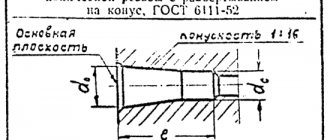
Conical inch thread has a triangular profile with an angle. It is cut on the conical surfaces of parts with a taper of 1:16. In the designation of a conical inch thread, indicate the letter K, the nominal diameter in inches and the standard number (Fig. 11).
Tapered pipe thread according to GOST 6211-81 has a triangular profile with an angle and a rounded top. It is cut on conical surfaces of parts with the same taper of 1:16. The dimensions of the thread in the main plane correspond to the dimensions of the cylindrical pipe thread.
In the symbol for pipe conical threads, the type of thread is indicated (the letter R is for external threads, the letter Rc is for internal threads) and the designation of the thread size (nominal diameter in inches). For example, a pipe conical external thread with a nominal diameter (Fig. 12).
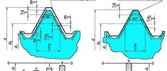
Running threads
Trapezoidal one-way thread according to GOST 9484-81 has a profile in the form of an equilateral trapezoid with an angle of 30° between the sides (Fig. 13, a). For each diameter, there are usually three steps. In the symbol for a one-way trapezoidal thread, the letters indicate the outer diameter and pitch, for example: (Figure 13, b).
Multi-start trapezoidal threads are designated by the letters nominal outer diameter of the thread, the numerical value of the stroke, and in parentheses the letter P and the numerical value of the pitch. A sign is placed between the nominal diameter and the thread stroke value, for example: The designation of the left-hand thread is supplemented with the letters LH, for example: (Fig. 13, c).
The thrust thread according to GOST 10177-82 has a profile in the form of an unequal trapezoid with an angle of 3° on the working side and 30° on the non-working side (Fig. 14, a). Like trapezoidal, thrust threads with the same diameter can have different pitches. The symbol for a thrust thread includes the letter S (indicating the type of thread), the nominal outer diameter and the pitch, for example: For a left-hand thread, the letters LH are indicated, for example: (Fig. 14.6).
The symbol for a multi-start thread contains the letter S, the nominal outer diameter, the stroke value, the letter P and the pitch value in brackets, for example: (Fig. 14, c).
Rectangular (square) threads are not standardized. Since the thread is not standardized, the drawing shows all the data necessary for its manufacture (Fig. 15). Rectangular threads have high efficiency, but have lower strength compared to trapezoidal and thrust threads.
Special threads
Special threads are:
- with a standard profile and non-standard pitch or diameter sizes. The designation of such threads includes the letters Cn (special thread), then indicate the designation of the thread, the dimensions of the outer diameter and pitch. For example, it means that the thread is a special metric thread with an outer diameter of 20 mm and a small non-standard pitch of 0.8 mm.
- threads having a narrow departmental purpose. For example:
- — eyepiece thread for optical instruments
- — Edison round thread for sockets and sockets of electric lamps.
Example notation:
- — round thread for sanitary fittings (for spindles of mixer valves, toilet and water taps) only with threads with a diameter of 12 mm.
Example of designation: where the thread diameter is 12 mm and the pitch is 2.54 mm.
Tapered, round and trapezoidal threads
Conical parts differ from ordinary ones in that a conical thread is applied to their surface. The angle is 1/16. Such products are used when it is necessary to seal connections. Manufacturers must comply with the requirements specified in GOST 25229–85. To designate parts, the letter marking MK is used. After this there are numerical parameters that correspond to geometric indicators.
The round profile is used in the manufacture of various pipeline valves and other shut-off valves. All standards for this type can be found in GOST 13536–68. In documentation, drawings and diagrams, the designation of the letters Kr is used. The angle near the top of the turns is 30 degrees.
The peculiarity of trapezoidal threads is that they are self-tapping. As the nut moves, a very high frictional force is created. Thanks to this, no additional fixation is required. Products of this type are produced in sizes 8–640 mm. The pitch of the turns varies from 1.5 to 12 mm. All requirements for finished parts are specified in GOST 24738−81.
Classification of threads, thread designation in the drawing
In mechanical engineering, standard cylindrical and conical threads of various types are used, differing from each other in purpose and parameters. The main element of the thread is its profile (Figure 14.1).
The thread designation includes the letter designation of the thread type and thread parameters. When designating a thread, its outer diameter (larger in size) is indicated.
For all threads, except conical and cylindrical pipe threads, designations are applied to the outer (larger) diameter and placed above the dimension line, on its extension or on the flange (Figure 2).
- Order drawings
Helix line. Basic thread parameters. Thread image
Products with screw surfaces are widely used in technology. These are fasteners used to connect parts of machines and mechanisms (bolts, nuts, screws, studs, threaded parts for connecting two parts), parts with helical surfaces used to convert rotational motion into translational motion (a worm paired with a worm wheel).
- The helix is obtained using a cutter.
- The thread is made using a cutter or tap and a die.
- A thread is characterized by pitch and stroke.
- There are right and left screw surfaces.
- Raising the helix to the right gives a right-hand thread (Figure a). b) - left-hand thread
Depending on the number of helical lines, threads are divided into single and multi-start.
Figure c) shows a double-start thread (n = 2)
Thread pitch is the distance between two adjacent screw flanges.
Thread lead is the distance between two adjacent helical protrusions of the same helical line.
, where is the number of visits
Drawing the projection of a helical surface is a very labor-intensive process. Therefore, in the drawings, the thread is depicted conventionally - as a solid thin line (thread cavity), and in views where the rod or hole is projected as a circle, the thread is depicted as an arc of a circle, approximately equal to the circle, open anywhere, but not on the center lines.
The distance between the solid main and thin lines is not less than 0.8 mm and not more than the thread pitch.
The thread boundary is drawn to the line of the outer diameter of the thread with a solid main thick line.
Invisible threads are shown with dashed lines of the same thickness along the outer and inner diameters
The designation of conical threads and cylindrical pipe threads refers to the contour of the thread (main solid line) and is applied only on the shelf of the leader line (Figure 15.3).
A rectangular thread with a non-standard profile is depicted as shown in Figure 15.4, with all dimensions applied. Additional information - the number of entries, the direction of the thread, etc. - is marked on the shelf with leader lines with the addition of the word “Thread”.
Elements and parameters of a rectangular thread can also be shown on the extension element (Figure 15.5).
The rule should be firmly remembered: in threaded connections shown in section, the thread of the rod covers the thread of the hole (Figure 15.6 a, b). Pay attention to the fact that in sections the shading is brought to solid main lines.
Thread run -out is the length of the section of an incomplete profile in the transition zone from the thread to the smooth part of the part. Usually it is not depicted (Figure 15.7)
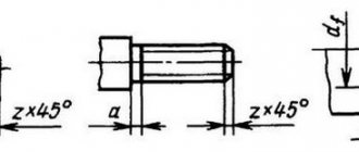
Chamfer - A beveled part of the surface of a part at the end or in transition areas, facilitating its assembly with other parts (the beveled edge of a rod or hole).
On a rod, the smaller diameter of the chamfer is smaller than the internal diameter of the thread. In a hole, the larger diameter of the chamfer is larger than the outer diameter of the thread.
The thread line must intersect the chamfer line.
Chamfers on a rod and in a threaded hole on a plane perpendicular to the axis of the rod or hole are not shown (Figure 15.8 a and b).
If the chamfer is not at an angle of 45°, then the chamfer designation is indicated by the angle as shown in Figure 15.9
External and internal grooves are made to exit the thread-cutting tool so that the thread has a full profile - without runs.
The dimensions of the grooves are applied on remote elements in accordance with GOST 10549-80 depending on the thread pitch
Basic information and areas of application
Most often, the threaded connection is made in the metric system. Thread sizes can be completely different. The coils are applied to the external or internal surfaces of any cylindrical element. This is the type of the most common fasteners:
- Nuts.
- Hairpins.
- Bolts.
- Screws (including those with a countersunk nut, requiring special holes prepared by countersinking).
- and so on.
Any of these parts has a thread run-out. In many technical specialties, drawing training begins with an image of the section and profile of a bolt. Such sketches are also present in the documentation for the technical operation of devices.
Products with a conical shape with a metric thread type are needed in cases where the connection requires high tightness. The angled profile eliminates the need for additional seals. This type has proven itself successfully during the installation of pipelines through which liquids and gases move. Pipe threads at low media pressures do an excellent job without gaskets. The conical type is also used when creating lids for various containers to seal the hole.
There is also a less common type of thread. It is called tape (rectangular). This type is used mainly in mechanical engineering.
The metric type of connections has a number of such parameters:
- Diameter.
- Thread pitch.
- Thickness and location.
- Height.
- Direction of turns.
To understand what a thread pitch is, just look at a regular bolt (it doesn’t matter whether it’s a hex head or a standard one). This is the distance between individual turns. There are other parameters due to which metric connections are divided into types that have their own symbols of letters and numbers.
Threaded connections have gained immense popularity due to a large number of advantages, including:
- Reliability and long service life.
- Ability to adjust the compression ratio.
- Simplicity of design.
- Fixation in a twisted position.
One of the disadvantages is the uneven distribution of the rated load over the entire width and length of the turns. If you frequently disassemble and reassemble the structure, this accelerates the wear of the elements. To extend service life, it is advisable to chamfer each time to the depth of the damage, but this is not applicable in all cases. Also, parts with different pitches will not fit together.
TOLERANCE FIELDS
7.1. The tolerance fields of external and internal threads established in accuracy classes (fine, medium and coarse) must correspond to those indicated in table. 10 and table. eleven.
Table 10
| Accuracy class | Make-up length | |||||||||
| S | N | L | ||||||||
| External thread tolerance field | ||||||||||
| Accurate | (3h4h) | 4g | 4h | (5h4h) | ||||||
| Average | 5g6g | (5h6h) | 6d | 6e | 6f | 6g | ||||
*Only for thread pitch P
³0.8 mm.
For threads with a pitch P
<0.8 mm, a tolerance field of 8h6h is applied.
Table 11
| Accuracy class | Make-up length | |||||
| S | N | L | ||||
| Internal thread tolerance field | ||||||
| Accurate | 4H | 4N5N | 6H | |||
| 5H | ||||||
| Average | (5G) | 5H | 6G | 6H | ||
Notes to the table 10 and 11:
1. Tolerance fields enclosed in boxes should be used preferentially.
2. The use of tolerance fields enclosed in brackets should be limited as much as possible.
3. At make-up lengths S
and
L
, it is allowed to use tolerance fields established for make-up lengths
N.
4. In justified cases, it is allowed to use thread tolerance fields formed by other combinations of tolerance fields for the average diameter and diameters of thread protrusions from those given in Table. 10 and 11, for example:
for external thread - 4h6h; 8h6h;
for internal thread - 5Н6Н.
7.2. Tolerance fields for external and internal threads indicated in table. 10 and 11 are a restrictive selection from the entire set of tolerance fields that can be obtained by various combinations of degrees of accuracy according to table. 2 and the main deviations according to table. 3.
Tolerance fields not listed in the table. 10 and 11 are special. Their use is allowed in technically and economically justified cases, if the tolerance fields according to table. 10 and 11 cannot meet the requirements for the product.
7.3. Limit deviations of external and internal threads corresponding to the tolerance fields specified in table. 10 and 11 are given in the mandatory Appendix 2.
7.4. In landings, any combination of tolerance fields for external and internal threads established by this standard is allowed.
It is preferable to combine tolerance fields of the same accuracy class.
Threads used in everyday life
When building houses and renovating apartments, the most common inch pipe threads are:
- ½ and ¼ - with a pitch of 14 turns/inch (or with a pitch of 1.814 mm)
- and also: 1, 1¼, 1½, 2 with a pitch of 11 turns/inch (or with a pitch of 2.309 mm)
Less commonly used is a plumbing round thread, or Edison profile.
The 11 TPI pitch is maintained on pipes ranging from 2 to 6 inches in diameter.
Pipe cylindrical thread
A ½ pipe is the main diameter for intra-house and intra-apartment wiring; it provides sufficient water pressure from the main; most faucets for bathtubs, toilets, showers, washing machines and dishwashers are designed specifically for this connecting size. ¼-inch pipes are used for the last meters of wiring to plumbing fixtures that do not require high pressure and flow, for example, sink faucets. ¾-inch pipes are used at the entrance to the apartment or at the distribution manifold of the pumping station of the local water supply system. Pipes of 1 and 1 ½ inches are used much less frequently in the construction of large cottages equipped with swimming pools.
TOLERANCES
3.1. The numerical values of the tolerances for the diameters of external and internal threads must correspond to those indicated in the table. 4 - 6.
Table 4
Diameter tolerances d
and
D1
| Pitch P , mm | External thread | Internal thread | ||||||
| Degree of accuracy | ||||||||
| 4 | 6 | 8 | 4 | 5 | 6 | 7 | 8 | |
| Tolerance, µm | ||||||||
| Td _ | T D 1 | |||||||
| 0,2 | 36 | 56 | — | 38 | 48 | 60 | — | — |
| 0,25 | 42 | 67 | — | 45 | 56 | 71 | — | — |
| 0,3 | 48 | 75 | — | 53 | 67 | 85 | — | — |
| 0,35 | 53 | 85 | — | 63 | 80 | 100 | — | — |
| 0,4 | 60 | 95 | — | 71 | 90 | 112 | — | — |
| 0,45 | 63 | 100 | — | 80 | 100 | 125 | — | — |
| 0,5 | 67 | 106 | — | 90 | 112 | 140 | 180 | — |
| 0,6 | 80 | 125 | — | 100 | 125 | 160 | 200 | — |
| 0,7 | 90 | 140 | — | 112 | 140 | 180 | 224 | — |
| 0,75 | 90 | 140 | — | 118 | 150 | 190 | 236 | — |
| 0,8 | 95 | 150 | 236 | 125 | 160 | 200 | 250 | 315 |
| 1 | 112 | 180 | 280 | 150 | 190 | 236 | 300 | 375 |
| 1,25 | 132 | 212 | 335 | 170 | 212 | 265 | 335 | 425 |
| 1,5 | 150 | 236 | 375 | 190 | 236 | 300 | 375 | 475 |
| 1,75 | 170 | 265 | 425 | 212 | 265 | 335 | 425 | 530 |
| 2 | 180 | 280 | 450 | 236 | 300 | 375 | 475 | 600 |
| 2,5 | 212 | 335 | 530 | 280 | 355 | 450 | 569 | 710 |
| 3 | 236 | 375 | 600 | 315 | 400 | 500 | 630 | 800 |
| 3,5 | 265 | 425 | 670 | 355 | 450 | 560 | 710 | 900 |
| 4 | 300 | 475 | 750 | 375 | 475 | 600 | 750 | 950 |
| 4,5 | 315 | 500 | 800 | 425 | 530 | 670 | 850 | 1060 |
| 5 | 335 | 530 | 850 | 450 | 560 | 710 | 900 | 1120 |
| 5,5 | 355 | 560 | 900 | 475 | 600 | 750 | 950 | 1180 |
| 6 | 375 | 600 | 950 | 500 | 630 | 800 | 1000 | 1250 |
Table 5
Diameter tolerances d2
| Nominal thread diameter d , mm | Step R , mm | Degree of accuracy | |||||||
| 3 | 4 | 5 | 6 | 7 | 8 | 9 | 10 | ||
| Tolerance Td2 , µm | |||||||||
| From 1 to 1.4 | 0,2 | 24 | 30 | 38 | 48 | (60) | (75) | — | — |
| 0,25 | 26 | 34 | 42 | 53 | (67) | (85) | — | — | |
| 0,3 | 28 | 36 | 45 | 56 | (71) | (90) | — | — | |
| St. 1.4 to 2.8 | 0,2 | 25 | 32 | 40 | 50 | (63) | (80) | — | — |
| 0,25 | 28 | 36 | 45 | 56 | (71) | (90) | — | — | |
| 0,35 | 32 | 40 | 50 | 63 | 80 | (100) | — | — | |
| 0,4 | 34 | 42 | 53 | 67 | 85 | (106) | — | — | |
| 0,45 | 36 | 45 | 56 | 71 | 90 | (112) | — | — | |
| St. 2.8 to 5.6 | 0,25 | 28 | 36 | 45 | 56 | (71) | — | — | — |
| 0,35 | 34 | 42 | 53 | 67 | 85 | (106) | — | — | |
| 0,5 | 38 | 48 | 60 | 75 | 95 | (118) | — | — | |
| 0,6 | 42 | 53 | 67 | 85 | 106 | (132) | — | — | |
| 0,7 | 45 | 56 | 71 | 90 | 112 | (140) | — | — | |
| 0,75 | 45 | 56 | 71 | 90 | 112 | (140) | — | — | |
| 0,8 | 48 | 60 | 75 | 95 | 118 | 150 | 190 | 236 | |
| St. 5.6 to 11.2 | 0,25 | 32 | 40 | 50 | 63 | (80) | — | — | — |
| 0,35 | 36 | 45 | 56 | 71 | 90 | — | — | — | |
| 0,5 | 42 | 53 | 67 | 85 | 106 | (132) | — | — | |
| 0,75 | 50 | 63 | 80 | 100 | 125 | (160) | — | — | |
| 1 | 56 | 71 | 90 | 112 | 140 | 180 | 224 | 280 | |
| 1,25 | 60 | 75 | 95 | 118 | 150 | 190 | 236 | 300 | |
| 1,5 | 67 | 85 | 106 | 132 | 170 | 212 | 265 | 335 | |
| St. 11.2 to 22.4 | 0,35 | 38 | 48 | 60 | 75 | 95 | — | — | — |
| 0,5 | 45 | 56 | 71 | 90 | 112 | (140) | — | — | |
| 0,75 | 53 | 67 | 85 | 106 | 132 | (170) | — | — | |
| 1 | 60 | 75 | 95 | 118 | 150 | 190 | 236 | 300 | |
| 1,25 | 67 | 85 | 106 | 132 | 170 | 212 | 265 | 335 | |
| 1,5 | 71 | 90 | 112 | 140 | 180 | 224 | 280 | 355 | |
| 1,75 | 75 | 95 | 118 | 150 | 190 | 236 | 300 | 375 | |
| 2 | 80 | 100 | 125 | 160 | 200 | 250 | 315 | 400 | |
| 2,5 | 85 | 106 | 132 | 170 | 212 | 265 | 335 | 425 | |
| St. 22.4 to 45 | 0,5 | 48 | 60 | 75 | 95 | 118 | — | — | — |
| 0,75 | 56 | 71 | 90 | 112 | 140 | (180) | — | — | |
| 1 | 63 | 80 | 100 | 125 | 160 | 200 | 250 | 315 | |
| 1,5 | 75 | 95 | 118 | 150 | 190 | 236 | 300 | 375 | |
| 2 | 85 | 106 | 132 | 170 | 212 | 265 | 335 | 425 | |
| 3 | 100 | 125 | 160 | 200 | 250 | 315 | 400 | 500 | |
| 3,5 | 106 | 132 | 170 | 212 | 265 | 335 | 425 | 530 | |
| 4 | 112 | 140 | 180 | 224 | 280 | 355 | 450 | 560 | |
| 4,5 | 118 | 150 | 190 | 236 | 300 | 375 | 475 | 600 | |
| St. 45 to 90 | 0,5 | 50 | 63 | 80 | 100 | 125 | — | — | — |
| 0,75 | 60 | 75 | 95 | 118 | 150 | — | — | — | |
| 1 | 71 | 90 | 112 | 140 | 180 | 224 | 280 | 355 | |
| 1,5 | 80 | 100 | 125 | 160 | 200 | 250 | 315 | 400 | |
| 2 | 90 | 112 | 140 | 180 | 224 | 280 | 355 | 450 | |
| 3 | 106 | 132 | 170 | 212 | 265 | 335 | 425 | 530 | |
| 4 | 118 | 150 | 190 | 236 | 300 | 375 | 475 | 600 | |
| 5 | 125 | 160 | 200 | 250 | 315 | 400 | 500 | 630 | |
| 5,5 | 132 | 170 | 212 | 265 | 335 | 425 | 530 | 670 | |
| 6 | 140 | 180 | 224 | 280 | 355 | 450 | 560 | 710 | |
| St. 90 to 180 | 0,75 | 63 | 80 | 100 | 125 | 160 | — | — | — |
| 1 | 75 | 95 | 118 | 150 | 190 | — | — | — | |
| 1,5 | 85 | 106 | 132 | 170 | 212 | 265 | 335 | 425 | |
| 2 | 95 | 118 | 150 | 190 | 236 | 300 | 375 | 475 | |
| 3 | 112 | 140 | 180 | 224 | 280 | 355 | 450 | 560 | |
| 4 | 125 | 160 | 200 | 250 | 315 | 400 | 500 | 630 | |
| 6 | 150 | 190 | 236 | 300 | 375 | 475 | 600 | 750 | |
| St. 180 to 355 | 1,5 | 90 | 112 | 140 | 180 | 224 | 280 | 355 | — |
| 2 | 106 | 132 | 170 | 212 | 265 | 335 | 425 | 530 | |
| 3 | 125 | 160 | 200 | 250 | 315 | 400 | 500 | 630 | |
| 4 | 140 | 180 | 224 | 280 | 355 | 450 | 560 | 710 | |
| 6 | 160 | 200 | 250 | 315 | 400 | 500 | 630 | 800 | |
| St. 355 to 600 | 2 | 112 | 140 | 180 | 224 | 280 | 355 | 450 | — |
| 4 | 150 | 190 | 236 | 300 | 375 | 475 | 600 | 750 | |
| 6 | 170 | 212 | 265 | 335 | 425 | 530 | 670 | 850 | |
Note. The values indicated in brackets should not be used if possible.
Table 6
Diameter tolerances D2
| Nominal thread diameter d , mm | Step R , mm | Degree of accuracy | ||||||
| 4 | 5 | 6 | 7 | 8 | 9 | |||
| Tolerance TD2 , µm | ||||||||
| From 1 to 1.4 | 0,2 | 40 | 50 | 63 | — | — | — | |
| 0,25 | 45 | 56 | 71 | — | — | — | ||
| 0,3 | 48 | 60 | 75 | — | — | — | ||
| St. 1.4 to 2.8 | 0,2 | 42 | 53 | 67 | — | — | — | |
| 0,25 | 48 | 60 | 75 | — | — | — | ||
| 0,35 | 53 | 67 | 85 | — | — | — | ||
| 0,4 | 56 | 71 | 90 | — | — | — | ||
| 0,45 | 60 | 75 | 95 | — | — | — | ||
| St. 2.8 to 5.6 | 0,25 | 48 | 60 | 75 | — | — | — | |
| 0,35 | 56 | 71 | 90 | — | — | — | ||
| 0,5 | 63 | 80 | 100 | 125 | — | — | ||
| 0,6 | 71 | 90 | 112 | 140 | — | — | ||
| 0,7 | 75 | 95 | 118 | 150 | — | — | ||
| 0,75 | 75 | 95 | 118 | 150 | — | — | ||
| 0,8 | 80 | 100 | 125 | 160 | 200 | 250 | ||
| St. 5.6 to 11.2 | 0,25 | 53 | 67 | 85 | — | — | — | |
| 0,35 | 60 | 75 | 95 | — | — | — | ||
| 0,5 | 71 | 90 | 112 | 140 | — | — | ||
| 0,75 | 85 | 106 | 132 | 170 | — | — | ||
| 1 | 95 | 118 | 150 | 190 | 236 | 300 | ||
| 1,25 | 100 | 125 | 160 | 200 | 250 | 315 | ||
| 1,5 | 112 | 140 | 180 | 224 | 280 | 355 | ||
| St. 11.2 to 22.4 | 0,35 | 63 | 80 | 100 | — | — | — | |
| 0,5 | 75 | 95 | 118 | 150 | — | — | ||
| 0,75 | 90 | 112 | 140 | 180 | — | — | ||
| 1 | 100 | 125 | 160 | 200 | 250 | 315 | ||
| 1,25 | 112 | 140 | 180 | 224 | 280 | 355 | ||
| 1,5 | 118 | 150 | 190 | 236 | 300 | 375 | ||
| 1,75 | 125 | 160 | 200 | 250 | 315 | 400 | ||
| 2 | 132 | 170 | 212 | 265 | 335 | 425 | ||
| 2,5 | 140 | 180 | 224 | 280 | 355 | 450 | ||
| St. 22.4 to 45 | 0,5 | 80 | 100 | 125 | — | — | — | |
| 0,75 | 95 | 118 | 150 | 190 | — | — | ||
| 1 | 106 | 13,2 | 170 | 212 | 265 | 335 | ||
| 1,5 | 125 | 160 | 200 | 250 | 315 | 400 | ||
| 2 | 140 | 180 | 224 | 280 | 355 | 450 | ||
| 3 | 170 | 212 | 265 | 335 | 425 | 530 | ||
| 3,5 | 180 | 224 | 280 | 355 | 450 | 560 | ||
| 4 | 190 | 236 | 300 | 375 | 475 | 600 | ||
| 4,5 | 200 | 250 | 315 | 400 | 500 | 630 | ||
| St. 45 to 90 | 0,5 | 85 | 106 | 132 | — | — | — | |
| 0,75 | 100 | 125 | 160 | — | — | — | ||
| 1 | 118 | 150 | 190 | 236 | 300 | 375 | ||
| 1,5 | 132 | 170 | 212 | 265 | 335 | 425 | ||
| 2 | 150 | 190 | 236 | 300 | 375 | 475 | ||
| 3 | 180 | 224 | 280 | 355 | 450 | 560 | ||
| 4 | 200 | 250 | 315 | 400 | 500 | 630 | ||
| 5 | 212 | 265 | 335 | 425 | 530 | 670 | ||
| 5,5 | 224 | 280 | 355 | 450 | 560 | 710 | ||
| 6 | 236 | 300 | 375 | 475 | 600 | 750 | ||
| St. 90 to 180 | 0,75 | 106 | 132 | 170 | — | — | — | |
| 1 | 125 | 160 | 200 | 250 | — | — | ||
| 1,5 | 140 | 180 | 224 | 280 | 355 | 450 | ||
| 2 | 160 | 200 | 250 | 315 | 400 | 500 | ||
| 3 | 190 | 236 | 300 | 375 | 475 | 600 | ||
| 4 | 212 | 265 | 335 | 425 | 530 | 670 | ||
| 6 | 250 | 315 | 400 | 500 | 630 | 800 | ||
| St. 180 to 355 | 1,5 | 150 | 190 | 236 | 300 | 375 | — | |
| 2 | 180 | 224 | 280 | 355 | 450 | 560 | ||
| 3 | 212 | 265 | 335 | 425 | 530 | 670 | ||
| 4 | 236 | 300 | 375 | 475 | 600 | 750 | ||
| 6 | 265 | 335 | 425 | 530 | 670 | 850 | ||
| St. 355 to 600 | 2 | 190 | 236 | 300 | 375 | 475 | — | |
| 4 | 250 | 315 | 400 | 500 | 630 | 800 | ||
| 6 | 280 | 355 | 450 | 560 | 710 | 900 | ||