Almost all electronic devices operate on direct current. This approach significantly reduces the number of electronic components used, the size of the circuit and the cost of manufacturing the device.
Rectifiers are used to convert alternating electrical voltage into direct voltage. The article will give a detailed explanation of what full wave rectifiers are. Describes their operating principle, varieties, main advantages and disadvantages.
Diode bridge.
A diode bridge is a small circuit made up of 4 diodes and designed to convert
alternating current to direct current. Unlike a half-wave rectifier, which consists of a single diode and allows current to pass only during the positive half-cycle, a bridge circuit allows current to pass during each half-cycle. Diode bridges are made in the form of small assemblies enclosed in a plastic case.
Four pins come out of the assembly body opposite which are marked “+
", "
-
" or "
~
", indicating where the bridge has
an entrance
and where
the exit is
. But not necessarily diode bridges can be found in the form of such an assembly; they are also assembled by connecting four diodes directly on the printed circuit board, which is very convenient.
For example. One of the diodes of the bridge has failed, if the assembly is still standing, then we safely throw it away, and if the bridge is assembled from four diodes directly on the board, we replace the faulty diode and everything is ready.
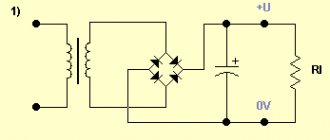
In circuit diagrams, a diode bridge is indicated by including four diodes in a bridge circuit, as shown in the left part of the lower figure: here, the diodes are like the arms of a rectifier bridge. This graphic designation of the bridge can be found in old magazines on radio engineering. However, today, basically, a diode bridge is designated in the form of a rhombus, inside of which there is a diode icon, indicating only the polarity of the output voltage.
Now let's look at the operation of a diode bridge using the example of a low-voltage rectifier. In such a rectifier, using four diodes, during each half-wave, two diodes of the opposite arms of the bridge, connected in series with each other, but counter to the second pair of diodes, operate alternately during each half-wave.
From the secondary winding of the transformer, alternating voltage is supplied to the input of the diode bridge. When on top
(according to the diagram) a positive half-cycle of voltage occurs at the output of the secondary winding, the current flows through diode
VD3
, load
Rн
, diode
VD2
and to
the lower
terminal of the secondary winding (see graph
a
).
Diodes VD1
and
VD4
are closed at this moment and no current flows through them.
During another half-cycle of alternating voltage, when the plus is on the lower
(according to the diagram) at the output of the secondary winding, the current flows through diode
VD4
, load
Rн
, diode
VD1
and to
the upper
terminal of the secondary winding (see graph
b
).
At this moment, diodes VD2
and
VD3
are closed and do not allow current to pass through themselves.
As a result, we see that the signs of the voltage on the secondary winding of the transformer change, and a current of one direction
(see graph
in
).
In such a rectifier, both half-cycles of alternating current are usefully used, therefore such rectifiers are called full-wave rectifiers
.
And in conclusion, we note that the operation of a full-wave rectifier compared to a single-wave rectifier is much more efficient:
1.
The ripple frequency of the rectified current has doubled;
2.
The gaps between pulses have decreased, which makes it easier to smooth out ripples at the rectifier output;
3.
The average value of the direct current voltage is approximately equal to the alternating voltage acting in the secondary winding of the transformer.
And if such a rectifier is supplemented with a filtering electrolytic capacitor
, then you can safely power an amateur radio design with it.
Well, you and I have almost finished studying diodes. Of course, not everything is given in these articles, but only the basic concepts, but this knowledge will already be enough for you to assemble your own amateur radio design for your home, which uses semiconductor diodes.
And for additional information, watch a video that tells you how to check a diode bridge with a multimeter
.
Good luck!
1. Borisov V.G - Young radio amateur. 1985 2. Goryunov N.N., Nosov Yu.R. - Semiconductor diodes. Parameters, measurement methods. 1968 3. Pasynkov V.V., Chirkin L.K. - Semiconductor devices: Textbook. for universities for special purposes “Semiconductors and dielectrics” and “Semiconductor and microelectronic devices” - 4th ed. reworked and additional 1987
Purpose
The main purpose of a single-phase full-wave rectifier is to convert alternating current into direct current. In order to understand the principle of operation of such a rectifier, it is necessary to understand what half-wave rectification is.
A half-wave rectifier is a device that consists of a transformer and one diode (valve) connected to the secondary winding of the transformer. The device works as follows:
- Sinusoidal current is a cycle of 2 periods: positive and negative.
- When a positive half-cycle flows through the circuit, the diode opens and passes it further along the circuit.
- When a negative half-cycle occurs, the diode does not open and cuts off this cycle.
This way, only high ripple current is passed through the circuit. In order to smooth out this effect, the circuit is supplemented with a high-capacitance capacitor. The main disadvantage of this scheme is the large current loss and the need to use powerful smoothing capacitors. A similar device is used, for example, for mobile phone charging units.
A full-wave single-phase rectifier is built according to approximately a similar circuit. The main difference is the addition of 2 or more semiconductor diodes to smooth both half-cycles. There are the following types of such elements:
- Mostovoy.
- With a midpoint.
Each device uses a different number of converters, which means it has a different operating principle.
Diode Characteristics
How to check a generator diode bridge with a multimeter
Let's look at the characteristics of the KD411AM diode. We look for its characteristics on the Internet, typing into the search “datasheet KD411AM”
To explain the parameters of the diode, we also need its current-voltage characteristic
1) Reverse maximum voltage Urev is the voltage of the diode that it can withstand when connected in the reverse direction, while current Irev will flow through it - the current strength when the diode is connected in reverse. When the reverse voltage in the diode is exceeded, a so-called avalanche breakdown occurs, as a result of which the current sharply increases, which can lead to complete thermal destruction of the diode. In our diode under study, this voltage is 700 Volts.
2) Maximum forward current Ipr is the maximum current that can flow through the diode in the forward direction. In our case it is 2 Amperes.
3) Maximum frequency Fd, which must not be exceeded. In our case, the maximum diode frequency will be 30 kHz. If the frequency is higher, our diode will not work correctly.
Diode Value Calculation
The diodes in full-wave rectifiers must withstand the load of alternating current, heat, and reverse voltage. When selecting a diode, you must consider:
- The output voltage to the diode should be 15–25% higher than the required value. For example, if you need to remove 12 volts of direct voltage, then the secondary winding of the transformer must produce at least 15–17 volts.
- The operating current threshold should be one and a half to two times higher than the rectifier current. The maximum current of each diode in the circuit can be found using the following formula:
- The value derived from the formula can be used to determine the value of the reverse voltage in the closing state. This value must be twice the output voltage of the transformer, otherwise reverse pn breakdown is possible. This is done according to the following formula:
It is also worth considering the material that is used as the semiconductor. Silicon elements are more resistant to reverse current loads and are capable of operating at temperatures up to +150 degrees. Germanium is less stable, its resistance to reverse voltage is about 400 volts.
Application of diode bridges
How does a voltage rectifier work?
And the short one is the cathode.
Parallel connection of LEDs If a 5 volt connection is necessary to install a pair of diodes, then a limiting type resistor with a resistance of no more than Ohms is connected to the electrical circuit in a series manner. In this case, it is worth remembering that the voltage drop across the LED will be the opposite for a conventional diode - VD1. When connecting LEDs of the same type in parallel, it is enough to calculate the parameters of one resistor, and the rest will be of the same value.
Used to simplify the designation of the two previous schemes.
This is the most important thing to remember. Due to this unfortunate event, all possible current will flow through the two surviving LEDs, naturally exceeding the rated one.
For calculation, you should take the maximum value of 3.7V. The maximum quantity is used in Chinese corn light bulbs, from 30 to LED pieces.
At the same time, a hole also forms in its old place. It involves a combination of parallel and serial connections. Diagram for connecting LEDs to volts Limiting the current level under alternating voltage conditions is carried out by resistors, capacitors or inductors.
Physical properties of pn junction
Minus on the first leg, plus on the second. Voltage drop across LEDs of different colors. It would seem that the situation can be corrected by the circuit shown in Figure 5. The first circuit of the rectifier device was assembled using radio tubes and was considered a complex and expensive solution. Comments on the article: 26 Good and bad circuits for connecting LEDs In previous articles, various issues of connecting LEDs were described.
The pulsations that appear must be removed, otherwise the electronic circuit will not be able to work normally. But we must not forget that some part of the voltage must remain for the quenching resistor, at least 2 volts. Figure 12 shows the SSC connection circuit for powering LEDs connected in parallel. The diode has very low internal resistance; if you turn it on without ampere limitation, it will burn out. LEDs based on solid solutions of zinc selenide ZnSe had a higher quantum yield, but they overheated due to high resistance and were short-lived. Rectifier circuits
Midpoint diagram
A midpoint full-wave rectifier involves a transformer with two secondary windings having a central terminal. A transformer with one secondary winding can also be used, but it will necessarily have an output from the center of the winding. In addition, the circuit contains 2 diodes. A rectifier with a zero terminal works due to the formation of EMFs of different directions. Both of these EMFs are equal in magnitude to the generated voltage relative to the center or 0 point. When such a transformer operates, the current on both half-windings is shifted in phase by 180 degrees.
The operating principle of this rectifier is as follows:
- The transformer has terminals “w21” and “w22”, which have opposite meanings.
- The anodes of the valves “vd1” and “vd2” are connected to these pins.
- The voltage applied to each diode is in opposite phase (“u21”–“u22” in the diagram).
- During the first half-cycle, current flows through the open diode “vd1”. Only current with a positive potential flows through its anode. During this half-cycle, the diode “vd2” is in a reverse bias state. It is locked and does not allow current from winding “w22” to pass through.
- During the second half cycle, a current with a positive potential is present at the anode “vd2”, thereby opening the diode. The diode passes current through itself from the “w22” winding. The diode “vd1” remains closed.
A full-wave zero-point circuit operates due to the absence of a bias torque. Each half of the secondary winding operates at its own half-cycle, which means the transformer is in a state of constant load.
pros
The zero-output circuit has advantages only over the single-cycle rectifier model. The main advantages of this scheme:
- During operation, current is transferred from both potentials, thereby saving up to 90% of the original energy.
- 2 diodes evenly distribute the load, extending their service life and significantly reducing the load on the entire circuit.
- The full-wave rectifier circuit assumes a smoothed current ripple, without the use of high-voltage, capacitive capacitors.
Despite a number of advantages, single-phase rectifiers with two diodes have their disadvantages, which will be discussed below.
Minuses
To operate such a clutch, you definitely need a special transformer with 2 secondary windings or one separated, with zero output. Such devices greatly increase the costs of producing high-voltage, powerful devices.
Also a big disadvantage is the reverse current load. The circuit must use diodes with a rated voltage of up to 1000 volts and the ability to withstand temperatures up to +80 degrees. If these parameters are not met, then when the diode closes, an increased temperature and resistance will form. Exceeding the parameters will lead to breakdown of the diode itself.
The next disadvantage is the use of the zero tap itself. Connecting to it involves only using part of the available energy, which greatly reduces the potential of such devices.
Purpose and practical use
Options for manufacturing power supplies for an 18 V screwdriver
The scope of use of a bridge made of diodes is quite wide. These can be power supplies and control units. It is installed in all devices powered by a 220 volt industrial network. For example, TVs, receivers, chargers, dishwashers, LED lamps.
Cars cannot do without it either. After starting the engine, the generator starts working, producing alternating current. Since the on-board network is all powered by constant voltage, a rectifier bridge is installed through which rectified voltage is supplied. The same constant signal also recharges the battery.
The rectifier device is used to operate the welding machine. True, it uses powerful devices that can withstand currents of more than 200 amperes. The use of diode assembly in devices provides a number of advantages compared to a simple diode. This straightening allows you to:
- increase the ripple frequency, which can then simply be smoothed out using an electrolytic capacitor;
- when working together with a transformer, get rid of the bias current, which makes it possible to more efficiently use the overall power of the converter;
- pass more power with less heat, thereby increasing efficiency.
But it is also worth noting the drawback due to which in some cases the bridge is not used. First of all, this is a double voltage drop, which is especially sensitive in low-voltage circuits. And also, when some of the diodes burn out, the device begins to operate in half-wave mode, which is why parasitic harmonics penetrate into the circuit, which can damage sensitive radioelements.
power unit
Not a single modern power supply can do without a rectifier. High-quality sources are manufactured using bridge rectifiers. The classic scheme consists of only three parts:
- A step-down transformer.
- Rectifier bridge.
- Filter.
A sinusoidal signal with an amplitude of 220 volts is supplied to the primary winding of the transformer. Due to the phenomenon of electromagnetic induction, an electromotive force is induced in its secondary winding and current begins to flow. Depending on the type of transformer, the voltage value is reduced by a certain value due to the transformation ratio.
An alternating signal with reduced amplitude appears between the terminals of the secondary winding. In accordance with the diode bridge connection diagram, this voltage is supplied to its input. Passing through the diode assembly, the alternating signal is converted into a pulsating one.
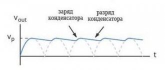
This form is often considered unacceptable, for example, for sound equipment or lighting sources. Therefore, a capacitor connected in parallel with the output of the rectifier is used for smoothing.
Three-phase rectifier
In production and in places where a three-phase network is used, a three-phase rectifier is used. It consists of six diodes, one pair for each phase. Using this type of device allows you to obtain a higher current value with low ripple. This, in turn, reduces the requirements for the output filter.
The most popular options for connecting three-phase rectifiers are the Mitkevich and Larionov circuits. In this case, not only six diodes can be used simultaneously, but also 12 or even 24. Three-phase bridges are used in diesel locomotives, electric vehicles, on drilling rigs, and in industrial gas and water purification plants.
Use and application
Today, bridges are widely used in all cases where direct current is used - from mobile phones to cars. The industry produces a large number of rectifier devices made using a bridge circuit. Therefore, choosing the right bridge is not difficult, provided you have a clear understanding of why it is being purchased and what functions it will perform.
Structurally, rectifiers can be made on separate diodes or as a single unit. In the first case, if one of the diodes is damaged, you can replace it. To do this, you need to know how to ring a diode bridge. The test is carried out in the form of a sequential search of all diodes to pass current in the forward and reverse directions. As an indicator, you can use either a regular light bulb or a device that measures current or resistance.
Read also: What is the designation of microfarad on a capacitor
Despite the availability of factory rectifiers, many are interested in how to make a 12-volt diode bridge on their own. The fact is that 12 volts is the most common voltage for powering many devices, for example, personal computers. And the desire to assemble a rectifier yourself is often quite justified. After all, most inexpensive power supplies that can be purchased do not meet the declared parameters for current and power.
Of course, a homemade unit is unlikely to look like a factory one, but it will allow you to connect devices in full accordance with the required parameters.
Despite the fact that the rectifier bridge is not a complex circuit, its assembly requires not only the ability to solder parts, but also correctly calculate their parameters. First of all, you will need a power transformer that reduces the voltage to 10 volts. The fact is that the output voltage of the bridge is approximately 18 percent higher than the input voltage. Therefore, if we supply 12 volts of alternating current to the rectifier, we will get 14-15 volts of direct current, and this can be dangerous for devices designed for 12 volts.
Next, you need to select diodes designed for a double current reserve. So, if it is assumed that the rectifier must provide a current of 5 amperes, then the diodes must withstand at least 10 amperes. The capacitor should also have a double reserve, but in terms of voltage. And in order to better smooth out the rectified current, it must have a large capacity. Therefore, the optimal solution is an electrolytic capacitor, designed for a voltage of 25 volts, with a capacity of 2000 microfarads. All these parts just need to be connected correctly and the output parameters checked using instruments.
Main characteristics
Let's consider the main characteristics of semiconductor diodes. Their designation in English-language technical documentation (the so-called Datasheet) is given in Latin letters:
- Vrpm is the peak or maximum reverse voltage. If this voltage is exceeded, the pn junction is irreversibly destroyed.
- Vr(rms) – average reverse voltage. Normal for operation, the same as Urev in the characteristics of domestic components.
- Io – average rectified current, the same as Ipr for domestic ones.
- Ifsm – peak rectified current.
- Vfm - voltage drop in forward bias (in the open conducting state) is usually 0.6-0.7V, and higher for high-current models.
When repairing electronic equipment and power supplies or designing them, beginners ask: how to choose the right diode bridge?
In this case, the most important parameters for you will be reverse voltage and current. For example, to select a 220V diode bridge, you need to look at models with a rated voltage greater than 400V and the required current, for example, KBPC106 (or 108, 110). Its technical characteristics:
- maximum rectified current – 3A;
- peak current (short-term) – 50A;
- reverse voltage – 600V (800V, 1000V for KBPC108 and 110, respectively).
Remember these characteristics and you can easily determine which option to choose from the catalog.
Features of rectifiers
The rectifier for the welding machine is made according to a bridge circuit. When manufacturing and using B200 diodes, it is necessary to take into account that their housing is energized.
Therefore, when the rectifier is installed on a radiator, it must be isolated from the rest of the circuit elements, from the device body and from neighboring diodes too. And this creates certain inconveniences for the welder.
You have to use a larger body. To reduce the dimensions of the device, a VL200 rectifier device is used, which has a different polarity. This allows semiconductors to be combined into two paired heatsinks.
In recent years, quite powerful diode bridges in one housing have begun to be produced. In size, such a design of diodes approximately corresponds to a matchbox, has a platform for landing a radiator, and a maximum forward current of 30-50 A. The diode assembly has a significantly lower cost compared to B200 diodes.
If the operation of the device requires a more powerful bridge, then this problem can be easily solved by using parallel connection of bridge assemblies. However, their reliability in this case will be lower than that of single powerful diodes.
How to make a diode bridge with your own hands
If necessary, and if you have the necessary diodes and a soldering iron, it is not difficult to assemble a diode bridge with your own hands.
What do you need for work?
To work, you need to prepare a workplace with a socket for a soldering iron, a soldering iron with a stand, solder, rosin, tweezers, and small wire cutters. Of course, you need diodes with the required characteristics. If desired, the bridge can be assembled on a printed circuit board with ready-made tracks.
Manufacturing instructions
| Illustration | Description of action |
| PHOTO: youtube.com | Preparation of the workplace |
| PHOTO: youtube.com | Soldering circuits |
| PHOTO: youtube.com | Instrument testing of the assembled circuit |
| PHOTO: youtube.com | Checking the circuit under load with a filter capacitor |
Functionality check
The first check is always visual. It is checked whether the parts are installed correctly, whether the circuit is assembled correctly, and the quality of soldering. Then a test circuit with a source and a measuring device is assembled. And if this stage was successful, then you can connect the load and conduct a final check of the results of your work.
Welding Application
Any transformer or inverter contains power diodes. They are designed to rectify alternating current. To increase the efficiency, the diodes are connected in a bridge circuit, in which case both half-cycles fall on the load.
In a transformer welding machine, rectifier diodes are installed at the output of the secondary winding. Welding equipment has a step-down transformer; accordingly, the no-load voltage is significantly lower than the input voltage, so high-power and low-frequency devices are required here. B200 rectifier diodes (maximum current 200A) are suitable for this.
The welding inverter requires two rectifiers. One is located at the input of the power source. It converts alternating current 220 volts 50 Hz into direct current, which is further converted into alternating current of high frequency (40-80 kHz).
With a device power of 5 kW, the rectifier diodes should have a reverse voltage of 600-1000 V and an average forward current of 25-35 A at a frequency of 50 Hz.
The second rectifier is located after the high-frequency transformer. Here the requirements are different. The maximum forward current must be at least 200 A at a frequency of 80 kHz, and the reverse voltage must exceed the open circuit voltage (60-70 V).
In any case, diodes from the powerful category are used, with a platform for mounting a radiator, since without heat removal the device will quickly burn out.
Semiconductor single-phase rectifiers for power supplies.
Classification, properties, diagrams, online calculator. Calculation of the capacity of the smoothing capacitor.“Why doesn’t the remote control work? “Of course, I’m not an electrician, but, in my opinion, the remote control doesn’t work because there’s no TV.”
- Why don’t we still need a professional electrician? - For what? Yes, for a lot of reasons! For example, in order to be aware that not a single electronic device can do without a power source, or more precisely without an AC to DC mains voltage converter. - What about the electrician? - Electrician, electrician... What is an electrician?... “Electrician Sidorov fell from a pole and cursed politely...”
So let's get started. A rectifier is an electrical device designed to convert alternating voltage into direct voltage. The rectifier contains a transformer necessary to convert the network voltage Uc to the value U2 determined by the load requirements; a valve group (in our case, a diode group), which ensures one-way current flow in the load circuit; a filter that transmits a constant voltage component to the output of the circuit and smoothes out voltage ripples .
Calculating a transformer is a cumbersome thing and will not be considered within the scope of this article, so let’s move on immediately to the main and most common circuits of rectifiers for power supplies of electronic equipment. In the process of narration, let's make the assumption that by the values of alternating voltages and currents in rectifier circuits we will mean their effective (effective) values: Uact = Uampl/√2 and Irms = Iampl/√2 . These are the values that are given in the passport characteristics of transformer windings, and most measuring instruments display nothing more than exactly the effective values of alternating current signals.
Half wave rectifier.
Fig.1
Figure 1 shows a single-phase, half-wave rectification circuit, as well as voltage oscillograms at various points (black - load voltage in the absence of smoothing capacitor C1, red - with a capacitor). In this type of rectifier, the voltage from the secondary winding of the transformer is supplied to the load through the diode only during positive half-cycles of the alternating voltage. During negative half-cycles, the semiconductor is closed, and voltage is supplied to the load only from the capacitor charged in the previous half-cycle. A half-wave rectifier circuit is used extremely rarely and only to power circuits with low current consumption due to the high level of ripple of the rectified voltage, low efficiency, and inefficient use of the overall power of the transformer.
Here, the transformer winding must provide a current value equal to twice the maximum current in the load Irev = 2×Iload and open-circuit voltage ~U2 ≈ 0.75×Un . When choosing diode D1 for this type of circuit, you should adhere to the following parameters: Uform > 3.14 × Un and Imax > 3.14 × In .
Let's move on. Full-wave rectifier with zero point .
Fig.2
The circuit shown in Fig. 2 is a combination of two antiphase half-wave rectifiers connected to a common load. In one half-cycle of the alternating voltage, current enters the load from the upper half of the secondary winding through the open diode D1, in the other half-cycle - from the bottom, through the second open diode D2. Like any full-wave rectifier circuit, this rectifier circuit has a ripple level that is 2 times lower than that of a half-wave rectifier circuit. The disadvantages include the more complex design of the transformer and the same as in the half-wave circuit - the irrational use of transformer copper and steel.
Each of the transformer windings must provide a current value equal to the value of the maximum current in the load Irev = Iload and open-circuit voltage ~U2 ≈ 0.75×Un . Semiconductor diodes D1 and D2 must have the following parameters: Uform > 3.14×Un and Imax > 1.57×In .
And finally, a classic of the genre - Bridge circuits of full-wave rectifiers .
Fig.3
Figure 3 on the left shows a circuit of a unipolar full-wave bridge rectifier using one transformer winding. The voltage graphs at the input and output of the rectifier are similar to the oscillograms shown in Fig. 2. During the positive half-cycle of the alternating voltage, current flows through the circuit formed by D2 and D3, during the negative half-cycle - through the circuit D1 and D4. In both cases, the direction of the current flowing through the load is the same.
If we compare this circuit with the previous rectifier circuit with a zero point, the bridge has a simpler transformer design with the same ripple level, less stringent requirements for the reverse voltage of the diodes, and most importantly, a more rational use of the transformer and the ability to reduce its overall power. The disadvantages include the need to increase the number of diodes, which leads to increased heat losses due to a greater voltage drop in the rectifier.
The transformer winding must provide a current value equal to Irev = 1.41×Iload and open-circuit voltage ~U2 ≈ 0.75×Un . Semiconductor diodes should be selected based on the following considerations: Uform > 1.57×Un and Imax > 1.57×In .
If the transformer has two identical secondary windings, or one with a lead tapped from the middle, the unipolar circuit is converted into a bipolar rectifier circuit with a middle point (Fig. 3 on the right). Naturally, bipolar diodes should be selected based on the double values of Urev and Imax in relation to a unipolar circuit.
The values of Urev and Imax are given based on the largest (amplitude) value of the reverse voltage applied to one diode, and the largest (amplitude) value of the current through one diode in the absence of smoothing filters at the output.
Capacitor C1 in all circuits is the simplest filter that isolates the DC component of the voltage and smoothes out voltage ripples in the load. For rectifiers that do not contain a stabilizer, its capacity is calculated using the formulas: C1 = 6400×In/(Un×Kp) for half-wave rectifiers and C1 = 3200×In/(Un×Kp) for full-wave rectifiers, where Kp is the ripple coefficient, numerically equal to the ratio of the amplitude value of the pulsating voltage to its constant component. For stabilized power supplies, the capacity of C1 can be reduced by 5-10 times.
“The ripple coefficient is chosen independently depending on the expected load, which allows DC power supply of a very certain “purity”: 10-3 ... 10-2 (0.1-1%) - small-sized transistor radios and tape recorders, 10-4 ... 10-3 (0.01-0.1%) - radio and intermediate frequency amplifiers, 10-5... 10-4 (0.001-0.01%) - preliminary stages of audio frequency amplifiers and microphone amplifiers.” - the printed publication teaches us authoritatively.
Well, at the end of the day, let’s present a simple online table.
RECTIFIER CALCULATOR FOR POWER SUPPLY.
And on the next page we will look at smoothing filters for power rectifiers, not only capacitive, but also inductive, as well as active filters on bipolar transistors.
Application areas of diode bridges
Diode rectifier bridges are used not only in welding units, but also in transformer devices. They are used in pulse rectifier devices. An example would be the power supply circuit of a conventional computer. Such rectifiers are used in compact fluorescent lamps; without them, energy-saving lamps do not work. A diode bridge is needed in various ballast electronic devices. They are installed in both single-phase and three-phase circuits.
Such assemblies are used in electricity meters, in control units for household appliances, which include televisions, washing machines, computers, power tools, mixers, vacuum cleaners, and refrigerators. Without them, industrial equipment circuits and cars do not work. In most cases today, instead of 1N4007 diodes, an assembly with the same characteristics MS500 is used. This diode bridge is equipped with leads located in 2.5 mm pitches. The assembly area is only 30 sq. mm. Its height is 1.6 mm.
You can assemble a diode bridge quite quickly and easily at home.
What is a car generator
A car generator is a unit that converts mechanical energy into electrical energy and performs the following functions:
- provides a constant and continuous charge of the battery when the engine is running;
- provides power to all systems during engine starting, when the starter consumes a large amount of electricity.
The generator is installed in the engine compartment. Using brackets, it is attached to the internal combustion engine block and driven by a drive belt from the crankshaft pulley. An electric generator is connected in an electrical circuit parallel to the battery. The battery is charged only when the electricity generated exceeds the battery voltage. The power of the generated current depends on the crankshaft speed; accordingly, the voltage increases with pulley speed with geometric progression. To prevent overcharging, the generator is equipped with a voltage regulator that regulates the amount of voltage at the output, providing 13.5-14.7V.
Diagram and operating principle of a diode bridge
Diode bridge diagram Fig. Highest operating rectification current.
With the advent of cheap semiconductor diodes, this circuit began to be used more and more often. The answer is shown in the following figure. They determined it without knowing anything about free electrons or holes.
The result is a higher degree of smoothing with the same capacitance of the filter capacitor, increasing the efficiency of the transformer used in the rectifier. If one diode in a monolithic assembly fails, the entire assembly will have to be replaced, despite the fact that the three remaining elements may be serviceable.
The pulsations are smoothed out, and the voltage becomes close to constant. Device connection diagram On electrical diagrams and printed circuit boards, a diode rectifier is indicated by a diode icon or in Latin letters.
As the name suggests, a bridge of 4 or 6 diodes is assembled. Working with both half-waves of alternating voltage, the diode bridge compares favorably with half-wave rectifiers.
Operating principle of a diode bridge
Metals are characterized by the fact that electrons in their crystal lattice almost do not stick, fly out and dangle between the atoms of the crystal for any reason, the slightest temperature, causing the nuclei of atoms in their places to vibrate slightly, knocks out the electrons completely and en masse. If you don't have a multimeter, you can use a regular voltmeter.
In this circuit, current flows from the phase with the highest potential, through the load to the phase with the lowest potential. This ripple can be slightly reduced by using a capacitor connected in parallel to the output of the diode bridge.
Its value increases and depends only on the resistance of the p- and n-regions. Rectifier design and connection diagram To date, nothing better has been invented for full voltage rectification than a conventional diode bridge. WHAT IS A DIODE BRIDGE
Principle of operation
The operating principle of this type of rectifier device is based on the property of a semiconductor diode to pass electric current in one direction and not in the other. So, if we connect the plus and minus correctly, current will flow through the device. If we swap the plus and minus positions, there will be no movement.
Alternating current differs in that during one half-cycle it moves in one direction, and during the second - in the opposite direction. And if you simply connect one diode to the circuit, then it will work “beneficially” only for one half-cycle. What if you connect the diodes so as to use both half-cycles? Thanks to this idea, bridge rectifiers appeared.
The diode bridge-rectifier circuit is quite simple and can be assembled with your own hands. It consists of four diodes connected in the form of a square. Alternating current is supplied to two opposite corners from a generator. A constant is removed from the other two opposite angles. During the first half-cycle, two diodes open, rectifying the half-wave of alternating current. During the second half-cycle, two other diodes open, converting the second half-wave. The result is a direct current output with a pulse frequency twice as high as the alternating current frequency.
Advantages and disadvantages of the scheme
- To use rectified current, the pulse component must be smoothed using a filter capacitor. The higher the frequency, the better the smoothing process. Therefore, doubling the frequency in a bridge circuit is an advantage.
- Full-wave rectification makes it possible to better utilize the power of the supply transformer and thereby reduce its size.
Flaws.
- Double the voltage drop compared to a half wave rectifier.
- Power loss due to heat dissipation is doubled. Low-dropout Schottky diodes are used to reduce losses in high-power low-voltage circuits.
- If one of the bridge diodes fails, the rectifier device will work, but its parameters will differ from normal. This, in turn, can negatively affect the operation of systems powered by a rectifier.
Rectifier faults
Since the generator rectifier assembly consists of several semiconductor devices and is protected by a cover in 90% of cases, diagnostics will require electrical tools and partial disassembly of the generator. However, in some cases, the driver can hear signs of a diode bridge malfunction:
- when pulsations occur (alternating voltage is supplied to the on-board network instead of direct voltage), the electric motors of some consumers can reproduce sounds by analogy with a speaker;
- Most often, the drive of the power windows and stove “squeaks”, and the tone changes when the speed of these devices changes, and not the crankshaft speed.
In all other cases, malfunctions of the vehicle generator in the rectifier assembly are diagnosed exclusively by instruments. To do this, you will need a diagram for connecting the diode bridge in a specific modification of the generator, since the symptoms of a mechanical failure are completely similar to the breakdown of electrical parts.
Diagnostics of breakdowns
The rectifier assembly is assembled using various technologies - some parts are attached mechanically, small diodes are soldered into the circuit, large ones are usually pressed in. Therefore, repair of the rectifier may be required, not only if the semiconductor elements fail, but also if they are installed incorrectly on the “horseshoe” of the heat sink plate.
The diagnostic technique is as follows:
- the back cover is removed from the generator to provide access to the diodes;
- the plate is supplied with a “–” wire from the battery, it is pressed against the housing on the generator, one wire of the lamp touches the diode at the point where the stator winding is connected, the second – to the “+” of the battery, if there is a breakdown, the light will light up;
- The tester is set to 1 kOhm ohmmeter mode; if you swap the multimeter probes, the readings should change from 0 to 400 - 800 Ohms in different directions.
Read more: I charge the battery and it boils
In most cases, the diode bridge burns when moisture penetrates.
Operation of a rectifier on a load with capacitive response.
Basically, radio amateurs use in their practical activities rectifiers with smoothing filters starting with a capacitor (capacitor), that is, a load with a capacitive response. There is no point in rewriting textbooks; for those interested, the list of references is at the end of the article. I’ll just briefly outline here the basic circuits of rectifiers used by radio amateurs, their features and approximate electrical characteristics, and how they affect the overall power of the transformer.
Half-wave rectifier.
Let's start as usual with a half-wave rectifier.
In such a rectifier, the filter capacitor is charged to the amplitude value of the voltage of the secondary winding (in the absence of load). That is, if the secondary voltage is 10 Volts, then the capacitor will charge to 10x1.41 = 14.1 Volts (this is without a voltage drop across the diode). Advantages of a rectifier;
Simplicity of the circuit, only one valve (diode, kenotron) is used.
Flaws;
Greater dependence of the output voltage on the load current, lower ripple frequency compared to other circuits, which requires the use of capacitors with twice the capacity, poor use of the transformer (low efficiency), and forced magnetization of the core.
When the valve breaks down, alternating voltage is supplied to the capacitor, which leads to its failure and explosion. Features of the scheme;
Used by radio amateurs to power low-current circuits. The reverse voltage in this circuit applied to the valve is approximately three times greater than the voltage of the secondary winding (more precisely 2.82 times), why this happens - try to determine for yourself. That is, if your secondary has a voltage of 100-110 Volts, then the diode must be set to a reverse voltage of at least 400 Volts; it can break through at 300 Volts. The average current through the valve here corresponds to the load current, and the effective value of the current through the valve is twice the load current.
The secondary winding for a half-wave rectifier is selected to be 1.8 -1.9 times higher in current (preferably 2 times) than the load current consumption. To the total calculated power of the transformer, if there are other windings, add the power of this load of yours multiplied by 2.
Full-wave rectifier.
A full-wave rectifier has much better parameters than a half-wave rectifier. The output voltage of this rectifier (capacitor voltage) is 1.41 times higher than the secondary winding voltage (half). This is when there is no load. Advantages of a rectifier;
Small number of valves used (2).
The average value of the current through the valve is almost two times less than the load current. The ripple level of this circuit is 2 times less compared to a half-wave rectification circuit. The capacitance of the capacitor, with the same ripple coefficient as the half-wave circuit, can be 2 times less. There is no forced magnetization of the core, but this depends on the design of the transformer and the method of winding the windings, which will be discussed below. Flaws;
The transformer has a complex design, the secondary winding consists of two halves, hence the inefficient use of copper.
The reverse voltage per valve here is also 2.82 times greater than the voltage (half) of the secondary winding. Poor use of the transformer, since the total calculated power of the entire secondary winding turns out to be 2.2 times the power consumed by the load. Features of the scheme;
Since in one period, in this circuit, both halves of the secondary winding work in turn, and accordingly, the valves (diodes) also work in turn, the average value of the current through one valve (per period) here is almost two times less than the load current . That is, for example, if you put diodes with a permissible constant current of 5 Amps in this circuit, then you can remove 7-8 Amps from this rectifier without much risk of failure of the diodes, naturally providing them with the necessary cooling. The effective current through the valve and the secondary winding here will be 1.1 times greater than the load current. The wire for the secondary winding in this circuit can be chosen 30-40% less in current (cross-section) than the load current, since the halves of the secondary winding also work in turn and the average value of the secondary winding current is less than the load current. But it is better, if the dimensions of the transformer and capabilities allow, to wind the secondary with a wire of the appropriate cross-section with the load current.
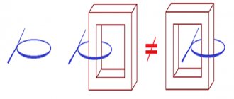
About the forced magnetization of the core. If the transformer core is W-shaped, armored, and all the windings are placed on one frame, then there will be no forced magnetization of the core. If the core of the transformer is rod-based and the design of the transformer includes two frames on which the windings are placed, and the network winding consists of two halves placed on different rods (TS-180, TS250), then the secondary winding in such transformers must be performed as follows; Each half of the secondary winding is divided in half again and wound on different rods, then everything is connected in series, first quarters of one half, then the other. As below in the picture. Otherwise there will be magnetization of the core.
Since kenotrons have high internal resistance, when choosing a kenotron rectifier circuit, the voltage of the secondary winding (half) is selected on average by about 10-15% less than the planned output voltage of the rectifier. It also depends on the load current. The higher the load current, the smaller the difference should be. Also remember that in all rectifiers, both with kenotrons and with diodes, the filter capacitors, when there is no load, are always charged to the amplitude voltage of the secondary winding (UC = U2 x 1.41). Take this into account when choosing the voltage of the filter capacitors.
How can we roughly determine here how much power will be added to the total power of the transformer? Without delving deeply into the theory, since there are a lot of factors that depend on each other, you can do the following;
Knowing the calculated load current, we multiply it by 1.7 (circuit with kenotrons), or by 1.6 (circuit with diodes), then multiply the result by the load voltage. This will be the approximate result of the received power, which will be added to the total power of the transformer. There won't be a big mistake here.
Bridge rectifier.
A bridge rectifier, like a full-wave rectifier, has much better parameters than a half-wave rectifier and slightly better efficiency than a full-wave rectifier. Therefore, this is the most common scheme. Advantages of a rectifier;
The average value of the current through the valve is almost two times less than the load current.
The ripple level of this circuit is 2 times less compared to a half-wave rectification circuit. The capacitance of the capacitor, with the same ripple coefficient as the half-wave circuit, can be 2 times less. There is no forced magnetization of the core. Only one secondary winding is used. Flaws;
Poor use of a transformer, since it is necessary to increase the calculated power of the secondary winding by the value of the amplitude value of the voltage of the secondary winding, i.e.
1.41 times. An increased number of valves used (4) and the need to shunt them with resistors to equalize the reverse voltage on each of them. Although this is no longer so relevant given the modern quality of their performance. The voltage drop is also twice as large compared to other circuits, since the rectified current passes through two valves in series. But this is noticeable only at low output voltage and high load currents. Features of the scheme;
In this circuit, just as in the full-wave circuit, the average value of the current through one valve (per period) is almost two times less than the load current. That is, you can also use diodes with a lower operating current (30-40%) than the load current. But the effective current of the secondary winding will always be higher than the load current, at least by 1.41. Therefore, the wire for the secondary winding in this circuit must be selected 1.5 times larger in current (cross-section) than the load current. Why, because the rectifier will always charge the filter capacitor to the amplitude value of the voltage of the secondary winding, and the power is calculated from the value of this voltage. And since, according to the law of conservation of energy, it does not disappear anywhere, the secondary winding has no choice but to constantly make up for this difference. That is, for example, our secondary winding has a voltage of 14 Volts. The filter capacitor will have a voltage of about 20 volts. We loaded it with a current of 0.5 Amperes. The power turned out to be 10 W. This means that the secondary should deliver 10 W, and with an output voltage of 14 Volts it will be a current of approximately 0.71 Amperes, that is, 1.41 times more than the load current.
The secondary winding in the bridge rectifier circuit will always supply energy to charge the capacitor up to the amplitude voltage value, and the load will discharge it. That is, it is like a step-up converter, where the low-voltage part is the secondary winding, and the high-voltage part is the filter capacitor. Therefore, the secondary winding current will always be higher than the load current by this voltage difference, that is, at least 1.41 times.
For example, you found a transformer with an output voltage of 24 Volts and a load current of 5 Amps (120 W). We assembled a linear adjustable power supply, connected it to a 12 Volt load and a current consumption of 5 Amps (60 W). It seems like everything should be fine. We drove for half an hour or an hour, there was a smell of burning, we touched the transformer and got burned. How so?
Let's check what we had with the transformer; The load current is 5 Amps, the voltage on the filter capacitor in XX mode will be 24x1.41 = 33.84 Volts. The power consumed by the load will be 33.84x5 = 169.2 W, and this does not depend on the output voltage of your power supply, at least 5 Volts, at least 25. The rest of the power will simply be lost on the regulating transistor. And it turns out that within an hour our trance delivered power to the load of 170 W!!!, although its power was 120.
Conclusion; For a bridge rectifier circuit, the cross-section of the secondary winding wire must be selected at 50% or 1.5 times greater than the planned load current to ensure normal operating conditions of the transformer, or choose a transformer for your design with a secondary winding current higher than planned by the same amount, so as the load current on the transformers is indicated for a resistive load.
Well, accordingly, the power of the secondary winding is calculated as follows: We multiply the load current by the voltage of the secondary winding and multiply the resulting result by 1.5.
How to calculate and select a diode bridge based on power
The maximum ripple voltage present in the full-wave rectifier circuit is determined not only by the value of the smoothing capacitor, but also by the frequency and load current and is calculated as:
Rectifier Bridge Ripple Voltage
Ripple Voltage Formula
Where: I is the DC load current in amperes, ƒ is the ripple frequency or twice the input frequency in Hertz, and C is the capacitance in Farads.
The main advantages of a full-wave bridge rectifier are that it has lower AC ripple for a given load and a smaller reservoir or smoothing capacitor than an equivalent half-wave rectifier. Therefore, the fundamental frequency of the ripple voltage is twice the AC frequency (100 Hz), where for a half-wave rectifier it is exactly equal to the supply frequency (50 Hz).
The amount of ripple voltage that is superimposed on top of the DC supply voltage by the diodes can be virtually eliminated by adding a greatly improved π filter (pi filter) to the output terminals of the bridge rectifier. This type of low-pass filter consists of two smoothing capacitors, usually of the same value, and an inductor or inductor across them to introduce a high-impedance path into the variable ripple component.
Bridge rectifier
Another, more practical and cheaper alternative is to use an off-the-shelf three-pole voltage regulator IC such as the LM78xx (where xx denotes the rated output voltage) for positive output voltage, or its inverse equivalent, LM79xx for negative output voltage, which can reduce ripple by more than 70 dB (datasheet), providing a continuous output current of more than 1 amp.
Many circuits with this technology are built with a bridge rectifier. Bridge rectifiers convert AC to DC using their diode system made of semiconductor material, either in a half-wave method, which rectifies one direction of the AC signal, or in a full-wave method, which rectifies both directions of the AC input signal.
Diode bridge GBL10
Semiconductors are materials that allow current to pass because they are made of metals such as gallium or metalloids such as silicon that are contaminated with materials such as phosphorus as a means of controlling the current. You can use a bridge rectifier for a variety of applications for a wide range of currents.
Bridge rectifiers also have the advantage of delivering more voltage and power than other rectifiers. Despite these advantages, bridge rectifiers suffer from the need to use four diodes with additional diodes compared to other rectifiers, causing a voltage drop that reduces the output voltage.
Smoothing
A single-phase electrical full-wave rectifier, no matter how many diodes it combines, requires additional smoothing of the output voltage. Ripple greatly affects the operation of the device itself for which such a rectifier is assembled. To smooth out current ripple, the rectification circuit is supplemented with filters. They can be collected from:
- High-capacity capacitor. Such a filter is a capacitive or “C-filter”. At the moment the diode opens, the capacitor is filled with current and plays the role of capacitance. At the moment the diode closes, the capacitance is gradually discharged, thereby smoothing out the voltage without any surges.
- Inductors. An inductor as a filter can be used in addition to or instead of a capacitor. This filter operates on the principle that there is no instantaneous change in the current across the coil. As a positive half-wave passes through the coil, the current value increases smoothly and slowly. When the half-wave changes to a negative value, the current in the coil changes with a delay, which significantly reduces the sharpness of the pulsation.
When designing diode rectifiers, the load of subsequent circuit elements is taken into account. So, if the resistance after the rectifier is significantly low, then using a capacitive filter is not advisable. At low loads, a larger capacitor will be required. Thus, for such circuits with low resistance, it is more rational to use an inductive filter.