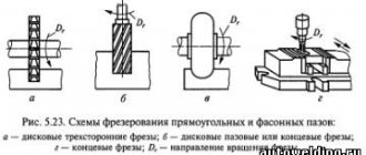
DIY lathe chuck
Even today, lathes play a huge role in the production of certain parts.
All components and all equipment on any machines change over time, as they are subject to wear. All these elements of equipment must be of high quality and durable, since the quality of the finished product depends entirely on the quality of the installed parts. So is the lathe chuck. It is without this element that the machine becomes useless. Below we will analyze everything related to this element of the lathe. Let's start by finding out what this part is.
Four jaw chucks
This type of chuck has jaws that move independently of each other, which gives it a wide range of possibilities. On the other hand, due to the need to center the workpiece, securing the part requires more time than with self-centering devices.
The simplest four-jaw lathe clamps are a cast iron faceplate on which the jaws are clamped with screws. The faceplate has radial grooves on which additional equipment can be placed.
For large machines, massive chucks with T-slots are used. The cams are moved by screws, the axis of which lies on the plane of the faceplate. These chucks often use compound jaws.
General concepts
The chuck is one of the main elements of turning equipment. It is due to this that the future workpiece is fastened (installed). It is attached to the headstock with the gearbox. The chuck mechanism consists of a cam device.
Purpose
It is this part of the machine that has the most important mission in any workpiece processing. Due to the cam mechanism, which is located inside the chuck itself, the workpiece is clamped and centered. This happens due to the simultaneous narrowing of the cams around the plane of the workpiece. After clamping the workpiece, the workpiece is clamped with a quill located on the tailstock. When these actions are completed, the machine starts and the part rotates, which can be processed.
Variety
Nowadays, lathe chucks are distinguished by the presence of fastening elements (jams). There are only three of these types:
Double cam
Such cartridges are capable of securing complex, asymmetrical and shaped parts. In such cartridges it is possible to secure surfaces that are not subject to treatment. They are used in small production, as well as in serial production.
Three cam
This type of equipment is the most common and is used in all work. Allows you to process round and hexagonal parts. This type of chuck uses three different jaws. Regardless of this, the workpiece is centered together with the clamping of all three cams.
Four cam
This type is used for processing rectangular workpieces. Here, for each cam, there is a separate mechanical unit, which makes all cams independent.
Types of jaw chucks
But the types of cartridges do not end with three types. They are also divided according to the mechanism for fixing the workpiece:
Collet
They consist of a sleeve with slots in which the petals are located (various modifications include from 3 to 6 petals). These petals act as cams.
Wedge
This type of equipment is used mainly on machines with numerical control. secured using 3 cams, which are located on a flat spindle.
Lever
These cartridges contain sliders, with the help of which the cams move by lever force. This type is used for small-scale production, as well as for processing a single workpiece.
Membrane view
In this case, a pneumatic drive is used, with the help of which the membrane is compressed. This type is used only for fine processing, to remove a thin layer of chips.
Drilling
These chucks are similar in principle to chucks for hand drills. When the nut is tightened with a special wrench, the cams are smoothly squeezed out. Due to this action, the part or tool is clamped.
Thermal cartridge
This type of device is very inconvenient to use. This is due to the fact that when attaching the workpiece, thermal heating of the chuck itself is performed, and the same actions are performed when removing the tool.
Hydraulic chuck
The principle of operation is similar to that of a thermal cartridge. The part is clamped by a liquid that compresses the cams under pressure. Due to the liquid contents in the cartridge, additional damping of vibrations that occur during operation is performed.
Design
Design of jaw lathe chuck
Let's look at the structural elements that make up the lathe chuck itself:
Used to carry out clamping actions.
Spring
Allows you to use the key to perform certain actions to clamp the part and vice versa.
Sleeve
Produces free passage of the key.
Stopper
Prevents the part from unscrewing while the machine is running.
Gear
Transmits rotational motion to the spiral disk.
Flange
The part on which the entire structure is fixed.
Spiral disc
Due to the rotational movement of the gear, this disk drives the cams.
Reverse cam
Used for clamping the workpiece from the inside.
Cam straight
Used for clamping the workpiece from the outside.
Frame
An element of a part on which the cam mechanism is located.
Overhead cams
For clamping long and short parts with large diameters.
Each of the parts of the entire mechanism performs a specific function and is not superfluous.
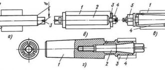
Assembly according to drawings
Drawing of a three-jaw chuck
The jaw chuck for turning equipment is assembled according to diagrams that can be downloaded from the Internet and printed on a printer. As a rule, factory cartridges cost a lot of money and therefore many have learned to make such parts homemade . Their design is simple, but quite understandable. Before you begin assembling this fixture, you must fully understand the entire mechanism of the chuck and cam mechanism. If it is not possible to make such elements yourself, then they can be ordered from any turner. It won't cost much.
Assembly begins with a flange on which all the necessary holes for fastenings are located. Following this, all the parts of the mechanism are gradually installed, which are completed by covering with the case and bolting the entire cartridge
Types of faceplates
The simplicity of the faceplate design and wide range of use have given rise to a large number of ways to secure workpieces. However, the device is not completely universal. Different situations may require several different modifications.
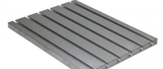
Faceplate with T-slots
On the surface of such equipment there are T-shaped grooves, similar to those used on tables of milling machines. Special stops or fastening nuts are inserted into these grooves. The workpiece is pressed to the plane using screws. The design of the device allows you to fasten almost any product. The arrangement of grooves on the surface of the disk is usually orthogonal. Depending on the purpose, the number and frequency of grooves may vary.
Faceplate with through grooves
This type is distinguished by the presence of grooves milled through the part. The workpiece is secured by installing screw clamps. In some cases, the part is simply screwed on from the reverse side. Grooves are most often located along a radius. There are also modifications with ring-type through grooves.
In most cases, grooved faceplates are used for metal lathes. Other turning devices can be easily installed on their surface.
Faceplate with holes
The working surface of the disk of this device has a number of holes located according to the dimensions of the workpiece being fixed. The central hole is threaded, necessary for direct fastening to the spindle shaft. The presence of threads in the mounting holes allows for fastening with standard screws. In other situations, the clamp is performed similarly to the previous option. When using a similar faceplate for a wood lathe, the future part is secured through the holes with ordinary self-tapping screws.
How to install a chuck on a lathe?
Installing a chuck on a lathe can be done using several methods, it all depends on the specific type of this element that you will be dealing with.
There are two types of chuck mounting on a lathe spindle:
Threaded fastening is used on small machines with light types of chucks, flanged on medium and heavy machines.
If it is light, it is quite easy to install on the machine without outside help, then heavy ones (more than 20 kg) are installed with the help of auxiliary lifting mechanisms, or in tandem with a partner. Let's consider the procedure for installing a heavy flange-mounted chuck on a lathe.
To install a heavy chuck, you need to prepare two mounting fixtures.
- mounting stand;
- guide
The mounting stand is made from a board approximately 50 mm thick. The width is equal to 1.5 times the width of the installed cartridge, the length of the stand L- corresponds to the width of the bed-B and the radius-D.
The blocks are attached to the bottom of the stand. Through vertical through holes, the stand is bolted to the movable rest of the machine support. The height of the stand is adjusted by the thickness of the bars.
Between the steady rest with the stand attached to it and the chuck still installed on the machine, the gap should be 1-3 mm.
The guide is a cylindrical shaft with a diameter of 25-40 mm, with a shank in the form of a Morse cone of at least number three. The length of the cylindrical part of the guide is equal to 1.5-2.0 times the width of the installed cartridge.
DISASSEMBLY AND REPAIR OF THE DRILL CHUCK
Currently, I am intensively engaged in repair and maintenance work around the house. There's a lot of drilling to do. Using one electric drill is more than difficult because you constantly have to change drills. Therefore, at work there were always two electric drills and a brace for delicate drilling of holes to large diameters. And so I decided to add a hand drill to this arsenal for countersinking holes, even if it is old, but it works. But the cartridge needs to be put in order - it rotates heavily, and there is a fair amount of runout.
Installation procedure
Before installing it, you should carefully check the condition of the surfaces of the spindle and chuck. Surfaces should not have nicks, scratches, burrs or contaminated areas.
Identified defects are eliminated point by point with a file or scraper. You should check the runout of the end and cone of the spindle landing base, which should not exceed three microns.
Place a metal rod or pipe with a diameter of about 20 mm into it. clasp it with your fists. With a partner, grasp the rod on both sides, or using lifting mechanisms, through the mounting loop, move the cartridge onto the mounting stand fixed to the machine support.
Install the guide in the tailstock. The chuck should be shifted by rolling towards the spindle axis.
Using a longitudinal feed, move it to the spindle flange so that the chuck studs do not reach the mounting holes of about 10 mm. The machine should be set to neutral speed to allow the spindle to rotate freely.
Move the tailstock with the quill completely retracted forward towards the chuck so that the guide extends over the entire width of the cam prisms and fix the tailstock.
Clamp the jaws of the chuck to transfer the weight to the guide. Align the key on the spindle flange with the mounting hole. Set the rotary washer to the position of the open holes. Using the quill, push the cartridge forward until it stops.
After making sure that all the stud nuts are out of the back of the spindle flange, turn the rotary washer to the locked position. Tighten the top nut with enough force to transfer the weight of the chuck onto the spindle. Open the cams and move the tailstock back. Compress the nuts according to the rule crosswise, evenly distributing the force between the studs.
After installation is completed, the chuck should be checked for axial and axial runout. If the standards are exceeded, it should be removed and all mating parts of this assembly should be carefully inspected.
Video: installation of a lightweight cartridge on a threaded fastener.
The ends of the spindles are threaded. GOST 16868 (Instead of OST 428)
Attaching the chuck to the threaded end of the spindle
GOST 16868 (Threaded spindle ends) offers two standard sizes of spindle ends:
Threaded spindle end GOST 16868
In reality, there are many models of machines produced before the early 60s , with threaded spindle ends from M33 to M150. The threaded end of the spindle was used on old model , for example, 1A62 (M90 x 6) and in small lathes - educational and desktop, for example, TV-7 (M45 x 4.5), etc.
TV-4 machine (d = M36 x 4), it is necessary to manufacture a non-standard intermediate flange using the mounting dimensions of the required chuck.
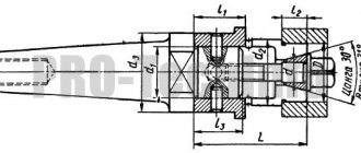
In order to secure a lathe chuck at the front end of the spindle, it is necessary to make or purchase an intermediate (adapter) flange , which is also called a faceplate .
On the spindle side, the intermediate flange must be screwed onto the spindle thread d and very accurately slide onto a cylindrical centering belt with a diameter of Ø d1 and a length of l mm.
On the side of the lathe chuck, the intermediate flange must have a centering belt - step D4 for precise installation and centering of the lathe chuck on the intermediate flange, and also have through holes for attaching the chuck. Obviously, for each standard size of lathe chuck there must be its own intermediate flange.
It is allowed to install 1 locking device against self-unscrewing on the intermediate flange of the design.
The disadvantage of threaded spindles is that when braking or reversing a high-speed machine, the chuck can jump off the spindle due to inertia. In addition, the lathe chucks mounted on these spindles with a sliding fit are not perfectly centered. Centering accuracy is affected by the clearance. With frequent screwing and unscrewing of cartridges, the gap increases due to wear of the mating surfaces. Under these conditions, even tight connections lose their original accuracy over time, and the need to repair the spindle head arises.
Medium and large lathes use flanged spindle ends with a centering short taper (7°7′30″). Tapered guides provide more accurate centering when installing chucks and faceplates.
DIY lathe chuck
Even today, lathes play a huge role in the production of certain parts. All components and all equipment on any machines change over time, as they are subject to wear.
All these elements of equipment must be of high quality and durable, since the quality of the finished product depends entirely on the quality of the installed parts. So is the lathe chuck. It is without this element that the machine becomes useless. Below we will analyze everything related to this element of the lathe. Let's start by finding out what this part is.
General concepts
The chuck is one of the main elements of turning equipment. It is due to this that the future workpiece is fastened (installed). It is attached to the headstock with the gearbox. The chuck mechanism consists of a cam device.
Purpose
It is this part of the machine that has the most important mission in any workpiece processing. Due to the cam mechanism, which is located inside the chuck itself, the workpiece is clamped and centered. This happens due to the simultaneous narrowing of the cams around the plane of the workpiece. After clamping the workpiece, the workpiece is clamped with a quill located on the tailstock. When these actions are completed, the machine starts and the part rotates, which can be processed.
Variety
Nowadays, lathe chucks are distinguished by the presence of fastening elements (jams). There are only three of these types:
Double cam
Such cartridges are capable of securing complex, asymmetrical and shaped parts. In such cartridges it is possible to secure surfaces that are not subject to treatment. They are used in small production, as well as in serial production.
Three cam
This type of equipment is the most common and is used in all work. Allows you to process round and hexagonal parts. This type of chuck uses three different jaws. Regardless of this, the workpiece is centered together with the clamping of all three cams.
Four cam
This type is used for processing rectangular workpieces. Here, for each cam, there is a separate mechanical unit, which makes all cams independent.
Types of jaw chucks
But the types of cartridges do not end with three types. They are also divided according to the mechanism for fixing the workpiece:
Collet
They consist of a sleeve with slots in which the petals are located (various modifications include from 3 to 6 petals). These petals act as cams.
Wedge
This type of equipment is used mainly on machines with numerical control. secured using 3 cams, which are located on a flat spindle.
Lever
These cartridges contain sliders, with the help of which the cams move by lever force. This type is used for small-scale production, as well as for processing a single workpiece.
Membrane view
In this case, a pneumatic drive is used, with the help of which the membrane is compressed. This type is used only for fine processing, to remove a thin layer of chips.
Drilling
These chucks are similar in principle to chucks for hand drills. When the nut is tightened with a special wrench, the cams are smoothly squeezed out. Due to this action, the part or tool is clamped.
Thermal cartridge
This type of device is very inconvenient to use. This is due to the fact that when attaching the workpiece, thermal heating of the chuck itself is performed, and the same actions are performed when removing the tool.
Hydraulic chuck
The principle of operation is similar to that of a thermal cartridge. The part is clamped by a liquid that compresses the cams under pressure. Due to the liquid contents in the cartridge, additional damping of vibrations that occur during operation is performed.
Design
Design of jaw lathe chuck
Let's look at the structural elements that make up the lathe chuck itself:
Used to carry out clamping actions.
Spring
Allows you to use the key to perform certain actions to clamp the part and vice versa.
Sleeve
Produces free passage of the key.
Stopper
Prevents the part from unscrewing while the machine is running.
Gear
Transmits rotational motion to the spiral disk.
Flange
The part on which the entire structure is fixed.
Spiral disc
Due to the rotational movement of the gear, this disk drives the cams.
Reverse cam
Used for clamping the workpiece from the inside.
Cam straight
Used for clamping the workpiece from the outside.
Frame
An element of a part on which the cam mechanism is located.
Overhead cams
For clamping long and short parts with large diameters.
Each of the parts of the entire mechanism performs a specific function and is not superfluous.
Assembly according to drawings
Drawing of a three-jaw chuck
The jaw chuck for turning equipment is assembled according to diagrams that can be downloaded from the Internet and printed on a printer. As a rule, factory cartridges cost a lot of money and therefore many have learned to make such parts homemade . Their design is simple, but quite understandable. Before you begin assembling this fixture, you must fully understand the entire mechanism of the chuck and cam mechanism. If it is not possible to make such elements yourself, then they can be ordered from any turner. It won't cost much.
Assembly begins with a flange on which all the necessary holes for fastenings are located. Following this, all the parts of the mechanism are gradually installed, which are completed by covering with the case and bolting the entire cartridge
Installation
Installing the jaw chuck
Installation is carried out as follows and in strict sequence:
Installation of the mandrel
First of all, this part is installed to ensure complete fitting of the cartridge.
Installing the chuck itself on the spindle
Using a frame, it is put on the spindle and secured with bolts.
Consolidation
The chuck is secured to the spindle with bolts. In this case, a simple open-end wrench will be a good helper.
Securing the workpiece
After installing the chuck, a part, workpiece or tool is fixed into it.
YORUMLAR • 70
Sorry, I gave the wrong link. Here's the correct one: trclips.com/video/q-jaGnanCQg/video.html
The same problem with satellites. I just chamfered it with a grinder: trclips.com/video/CJlAlZH6Nps/video.html
Everything would be fine. Only after sanding the grooves of the satellites, they would need to be washed with something.
what brand of machine?
I still haven't received an answer to my previous question.
The diameter is the same, but it is better to grind it locally.
@Sergey Aleksandrovich Is the diameter of the collar for mounting the cartridge the same? It’s just that my faceplate is still completely new (flat) and I need to machine a groove in it to fit the cartridge so that it fits tightly. And in the future, buying a Chinese cartridge, I’m thinking of sharpening the faceplate now.
I did not center the Soviet one. There was no indicator. Just installed and bored the cams. The mounting holes are slightly offset from the center, 1-2 dozen.
Hello. Tell me, how identical are the seats of this cartridge and the Soviet one (in particular, the diameters of the groove for the faceplate shoulder)? In the video you can see that you center the cartridge by hitting it through a wooden spacer. Did the Soviet one also have to be centered on this faceplate?
Sanych, Uncle Maxim for an injection. will say for sure))))))))))))))))
You should have marked the inside, you upset the balance, oh master master.
The cartridge on the adapter flange should fit with a slight interference, and not dangle like yours. You can lubricate the snail only with liquid oil, and only the gear drive with thick lubricant. Usually, after work, I took out the cams, cleaned them, sprayed them with oil, during idle time the excess oil drains and during operation, what is left does not fly apart.
I won’t sharpen the faceplate a second time.
I’m not a turner myself, but I looked it up to expand my knowledge. Thank you, Sanych. Shoot some more. By the way, when will the flea market be?
Go wild at flea markets trclips.com/video/M5j4uk1eSB8/video.html
Prima Wartung! Ich habe genau das Selbe Drehfutter und mache es genau so! Habe es heute justiert: trclips.com/video/dhnXiJijaXo/video.html ca. 1/100 Abweichung
I have a Belarusian one. 125 mm dia. Excellent quality.
where can I find out about the demagnetization device?
Thank you for the video. May I know what kind of degausser this is? Design, elements, what is it powered by?
I cleaned and lubricated my Sanou chuck too, much improved function. I also cleaned and oiled the Sanu cartridge, significantly improving the function. Your calibration of assembly is best method ever. Your calibration is done in the shortest way possible.
A well-known turner from the collective farm MTM said that the lathe chuck cannot be lubricated ((But when was that? By the way, any collective farm turner in the MTM could be classified as a generalist! That is, his tasks radically change every half hour!! Now he is sharpening a hairpin , and then he grinds the welded shaft! But that was already at least 10 years ago ((Now there are no collective farms anymore and MTM is rarely seen anywhere ((The turner said that once a week he disassembled the cartridge and blew it out with compressed air! By the way , he worked on 1K62, 58th year of manufacture, i.e. 3 years older than me)))
Varieties
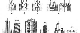
To bore the jaws of a lathe chuck, it is necessary to choose the optimal method for a particular type. Several types of cams are produced, each of which has design features.
Direct
This type of cam is designed to clamp a workpiece with a shaft on the outside and for a workpiece with a hole on the inside. The cams are directly located on top and grip the part.
Reverse
Necessary for clamping the workpiece from the outside. Used for processing hollow blanks so that there is something to cling to.
Invoices
This is a composite version of the cartridge, which is made of non-ferrous metal or stainless steel. Used when working with large-scale projects. This variation is used when working with workpieces of large diameter, and it does not matter whether they are long or short.
Prefabricated
A metal cam in this type is mounted on a steel rail. Alloy steel is used, and the cam teeth are ground, hardened and carburized.
How to squish it correctly?
To properly bore the cartridge, you must follow the sequence of actions. Professional boring is carried out in several stages, each of which must be performed with high quality and in accordance with all technical requirements.
Dismantling
First of all, it is necessary to dismantle the cartridge. Otherwise, it will not be possible to get rid of the workpiece runout and accurately align all the necessary axes. If the chuck is not clamped, but is in a free state on the machine, the defects will remain. After dismantling, it is necessary to remove the cams and clean them. Then you need to check the runout.
Sandpaper treatment
If there is a slight degree of wear and scuffing, it is enough to treat the part first with coarse-grained and then fine-grained sandpaper. In order not to distort the cam profile when sanding, it is necessary that the sandpaper covers approximately half of the cam profile and at the same time have a slight tension. If the cam wear is significant, full boring is necessary.
How to sharpen?
To groove the cams, a certain order must be followed:
- Install them by aligning them with the hole in the lathe chuck.
- Clamp the ring so that it can move freely.
- You will need two cutters: one for boring grooves, and the second for developing planes.
- Starting from low speeds, you should find the optimal rotation mode.
- The cutter for disassembling the planes must be installed so that contact occurs along the entire plane of the fists.
This way, conical boring is carried out and the workpiece can be fastened securely and safely.
Grinding
This is the final stage of boring, which is carried out only if there is a real need. At the same stage, a test is carried out with a metal shaft. The shaft is fixed in the chuck of the lathe and with its help it is possible to determine whether there is any runout. If there is runout, additional grinding is required.
To come in
Already registered? Sign in here.
There are currently 0 users on the page
There are no users viewing this page.
A method for restoring worn universal lathe chucks in repair production conditions is presented. Technologies for the restoration of individual elements are given.
Fig.1. 3 jaw chuck
Currently, in the main and repair engineering production, a large number of lathe chucks are used, which are used to install and secure workpieces of parts for various purposes. Over time, the elements of the cartridges wear out and there is a need to restore them in order to save money on these devices. The cartridge to be restored should be disassembled and its elements defective.
The body of a lathe chuck with through cracks cannot be restored. The body of the chuck being repaired must not be re-threaded to secure the cover, small bevel gear, or rack to secure the cam. If the threads in the indicated places are worn out, then you should drill out the holes and press plugs into them, in which you need to cut a new thread according to the dimensions indicated in the cartridge drawing.
If there is a one-sided or two-sided break in the cam guide in the body, it can be restored in the following sequence. Use an end mill on a vertical milling machine to remove the broken protrusion, and then use a T-shaped cutter to make a new groove and press a strip into it that corresponds to the direction dimensions given on the chuck drawing.
The restoration of the large bevel gear should be carried out in the following sequence [1]. This part must be installed and secured in the chuck of a lathe and checked for runout along the outer diameter and ends (permissible deviation 0.05 - 0.1 mm) and ground worn teeth along a cone, leaving traces of these teeth 4 - 5 mm high . Then the spent teeth should be fused. Surfacing can be performed with electrodes made of steel grades 20 or 45 [2]. The first layer of surfacing should be applied along the depressions of the spent teeth from the outer diameter of the gear to its hole. After surfacing the first layer, it must be cleaned of scale with a wire brush. Then the second layer is deposited: first along the edge of the outer diameter, then the inner diameter, and then the middle one. The thickness of the deposited metal layer should be 2–5 mm higher than the level of the end. After surfacing, the gear must cool in air [3].
The gear to be restored is installed and secured in the lathe chuck and checked for runout along the outer diameter and end with an accuracy of 0.1 mm. Then the gear is rotated along the outer diameter and the deposited layer along the cone. Then the gear is reinstalled in the chuck and the hole and second end are controlled with a cutter and the spiral is cleaned. Then the gear teeth are cut on a horizontal milling or gear planing machine [4].