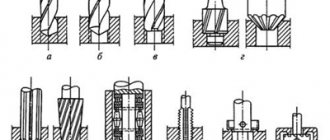
Mandrels with one-sided collet
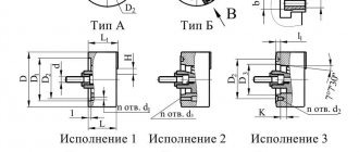
Mandrels with a single-sided collet are used for light work. The base surface of the workpiece must be processed taking into account the expansion of the collet to 0.5 mm. Recommended hole diameters for workpieces are 15 mm and above.
Dimensions, mm
| D | d (additional deflection for A/C) | d1 (additional deflection for A/G) | d2 | d3 | L | l1 | l2 | l3 |
| 15—20 | 6,5 | 17 | 22 | 27 | 36 | 19 | 7 | 17 |
| 21—25 | 8,5 | 23 | 28 | 33 | 47 | 22 | 10 | 20 |
| 26—30 | 10,5 | 28 | 33 | 38 | 54 | 24 | 12 | 22 |
| 31—35 | 10,5 | 33 | 38 | 43 | 61 | 26 | 16 | 24 |
| 36—40 | 12,5 | 38 | 43 | 48 | 74 | 29 | 20 | 27 |
| 41—45 | 16,5 | 45 | 50 | 55 | 82 | 32 | 20 | 30 |
Features of collet chucks
The main feature of the collet chuck, which is its advantage over other types of clamping equipment, is the uniform fixation of the working tool. The collet, under the influence of the nut, comes into contact with a large area of the cutter shank, which significantly reduces the level of vibration and deviation of the tool from the axis under lateral loads. All this together increases the accuracy of metal processing, allowing you to work with small parts while maintaining the necessary parameters of the finished product.
Another advantage of collet chucks for routers is the versatility of the equipment. Due to the fact that collets of different diameters can be inserted into the same chuck, it is possible to work with a large assortment of cutters without replacing the body itself. All this expands the possibilities in metal processing and also significantly speeds up the work process. The procedure for changing the cutting tool and collet also does not take much time - the nut can be unscrewed quickly enough by hand after loosening it with a wrench.
Mandrels with smooth collet
Mandrels with a smooth collet are used for light to medium work. The base surface of the workpiece must be processed taking into account the expansion of the collet to 0.5 mm.
Dimensions, mm
| D | d | d1 | L | l1 | l2 |
| 20-25 | 9,8 | M20x1.5 | 40 | 40 | 20 |
| 26—38 | 12,8 | M24X2 | 55 | 55 | 25 |
| 39—54 | 17,8 | M36x2 | 80 | 80 | 32 |
| 55—78 | 27,7 | M48x3 | 115 | 115 | 43 |
How to make your own collet chuck
When making various products with your own hands, situations arise when the available equipment does not allow you to perform the necessary operations. It is required to produce a collet chuck that meets the requirements, with the product being manufactured according to the developed sketch.
All work must begin with the preparation of a sketch with the elaboration of all the necessary details. The sketch of the chuck allows you to take into account all the features when making the necessary equipment and clamping mechanism with your own hands.
When making collets with your own hands, you need to consider several features:
- the internal diameter of the collet is equal to or less than the minimum diameter of the part;
- in a collet, an increase in the internal diameter is possible due to the expansion of the petals;
- to increase the production of adjustable collets after setting and improve the quality characteristics, additional grinding of the conical and guide parts of the collet is necessary;
- It is necessary to take into account that during long-term operation the elasticity of the collet blades is lost, as a result of which breakage may occur.
Self-centering collet plugs
Self-centering collet plugs are used for medium-sized jobs. The collet is expanded by pressure from the center. The base surface of the workpiece must be processed taking into account the expansion of the collet to 0.5 mm.
Dimensions, mm
| D | d | d1 | L | l | l1 | l2 |
| 30—34 | 26 | M20x1.5 | 65 | 32 | 27 | 16 |
| 35—39 | 33 | M20x1.5 | ||||
| 40—44 | 37 | M24x2 | 75 | 38 | 31 | 17 |
| 45—49 | 43 | M30x2 | 80 | 22 | ||
| 50—54 | 48 | M42X3 | 90 | 48 | 41 | |
| 55—60 | 53 | M42X3 |
Design Features
Collet chucks vary in type and size, but they all work on the same principle. The equipment consists of a set of collets and a self-clamping nut, which creates pressure on the end of the collet. Due to the pressure force, the collet moves into the tapered opening, simultaneously decreasing in diameter and providing a compression force on the part or tool shank. To remove the part, the nut is screwed together, increasing the diameter of the collet.
There are chucks with retractable, fixed and retractable collets. According to its purpose, this element can be a feeder or a clamping element. The feeder is a sleeve with three springy petals and ends directed towards the center. The collet is screwed onto a rotating rod, which feeds the workpiece through a cam mechanism or hydraulic drive. The elasticity of the petals ensures tight compression of the tool or part.
The design of the one-piece collet is a spring bushing with petals. The number of petals depends on the diameter of the part being fixed:
- three-lobed – parts or tools with a diameter of up to 3 mm;
- 4-petal – from 3 to 80 mm;
- 6-petal – parts with a diameter of more than 80 mm.
To fasten parts and tools of the smallest diameter, chucks with detachable clamping collets are used. The movement and fixation of the cams in this design is provided by special springs.
Mandrels with double-sided collet
Used for light work. The base surface of the workpiece must be processed taking into account the expansion of the collet to 0.5 mm.
Dimensions, mm
| D | d (additional deflection for A/C) | d1 | TO | l | l1 | L |
| 40—44 | 20 | 28 | 10 | 62 | 35 | 90 |
| 45—49 | 30 | 15 | 70 | 100 | ||
| 50—54 | 25 | 33 | 80 | 45 | 110 | |
| 55—59 | 30 | 38 | ||||
| 60—65 | 46 | 20 | 100 | 125 |
Types and principles of operation of chucks
Collet chucks are used mainly when processing cold-rolled rods or other metal products that have an already machined surface.
Structurally, cartridges can be classified according to functionality:
- with a fixed mechanism;
- with retractable mechanism;
- with retractable mechanism.
Each design has its own characteristics. The feeding type is made in the form of a steel sleeve with 3 cuts forming petals that have a springing effect.
Drawing No. 1 of the main spindle collet
Type F
Collets type F - clamping the main spindle are used to secure the workpiece.
Drawing No. 2 of the counter-spindle collet
Type LN
Collets type LN - counter spindle are produced elongated, size E depends on the standard size.
Drawing No. 3 collet type R
Type R
Type R – are pull-type collets.
Drawing No. 4 collet type T
Type T
Type T - clamping.
Drawing No. 5 collet BF
Type BF
BF type feed collet - designed for bar feeding.
When installed on the machine, the feed collet is threaded onto the pipe with the help of which it is fed into the working area. It is necessary to take into account the design feature - the size and shape of the collet, which must necessarily correspond to the profile of the bar being processed.
In preparation for processing, the rod moves through the petals, which, due to their design features, tightly hold the workpiece. During processing, when feeding the workpiece, the adhesion force between the petals and the product increases due to rotation. The principle of operation of the clamping elements is based on strengthening the adhesion of the petals to the workpiece during rotation of the working mechanism. Bushings with 3 petals are used for processing products up to 3 mm, four – up to 80 mm, six – over 80 mm. Typically, collets have an angle at the apex of the cone equal to 30º.
Collets for shaft 2 mm (0.1-3 mm) for micro drill
When processing thin rods, collets equipped with springs are used to increase the clamping force of the jaws. When increasing the diameter of the workpiece being processed, designs are used that are equipped with special inserts selected according to the dimensions of the product. Collet clamps are also used when machining with a drill, cutter or tap. The sleeve is fixed in the chuck with a nut, and the cutting tool is fixed directly in the collet. When fixed with a nut, the internal volume of the hole where the workpiece is installed is reduced, thereby increasing the force holding the rod stationary.
Cartridges of this design also have their drawbacks. First of all, the requirement that the shanks of the tool used must match the characteristics of the collets used. At enterprises, the most widely used collets are the ER type, which constitute the largest number in the total volume of tools used.
When performing complex work on the manufacture of products, various collets are used, indicating all sizes and technology for performing work operations, but often it is necessary to combine equipment or make the necessary collet chuck with the required characteristics with your own hands.
Video review of a lathe collet chuck
Collet mandrels for stepped holes
Used for light work. The base surface of the workpiece must be processed according to 2 or 3 accuracy classes.
Dimensions, mm
| D | D1 | d (additional deflection for A/C) | d1 | d2 | d3 | TO | l1 | l2 | l3 | L |
| 25—29 | By workpiece | 12 | 15 | D— 1 | 22 | 8 | 32 | 24 | 80 | 105 |
| 30—34 | 15 | 18,5 | 28 | 12 | 45 | 33 | 100 | 125 | ||
| 35—39 | 20 | 20 | 33 | 15 | 55 | 41 | 125 | 150 | ||
| 40—44 | 20 | 25 | 37 | 20 | 60 | 51 | 140 | 165 | ||
| 45—48 | 25 | 30 | 42 | 20 | 60 | 61 | 160 | 185 | ||
| 50—54 | 25 | 35 | 47 | 20 | 60 | 66 | 170 | 200 | ||
| 55—60 | 30 | 36,5 | 51 | 20 | 65 | 69 | 182 | 210 |
Mandrels with collet tightening through the spindle
Used for medium work. The base surface of the workpiece must be processed taking into account the expansion of the collet to 0.5 mm.
Dimensions, mm
| D | d(additional deflection A3/C3) | d1 | d2 | d3 | l1 | l2 | l3 |
| 45—49 | 26 | 29,5 | 60 | 40 | 35 | 25 | 175 |
| 50—54 | 35,5 | 60 | 45 | ||||
| 50—59 | 37,5 | 70 | 50 | ||||
| 60—64 | 41,5 | 70 | 54 | ||||
| 65—70 | 45,5 | 80 | 58 | 40 |
Collet mandrels with adjustable clamp
Used for light work. The base surface of the workpiece can be machined with large deviations.
Dimensions, mm
| D | d | d1 | d2 | d3 | TO | L | L1 | l | l1 | l2 | l3 | l4 |
| 48—54 | 19 | 25 | 44 | 38 | 25 | 235 | 170 | 40 | 85 | 30 | 15 | 15 |
| 55—64 | 20 | 25 | 50 | 42 | 25 | 250 | 185 | 100 | ||||
| 65—74 | 25 | 30 | 60 | 50 | 30 | 290 | 220 | 60 | 110 | 45 | 20 | 20 |
| 75—84 | 30 | 40 | 70 | 60 | 35 | 320 | 250 | 130 | ||||
| 85—95 | 35 | 40 | 80 | 70 | 35 | 365 | 275 | 70 | 145 | 25 |
Expanding mandrels with rollers
Used for medium work. The clamping is carried out by jamming the rollers between the workpiece and the mandrel. The base surface of the workpiece can be processed according to 8-9th accuracy classes.
Dimensions, mm
| D (additional deflection according to WITH ) | D1 | D2 | d (additional deflection according to C) | L | l | l1 |
| 25 | 19 | 30 | 6,05 | 100 | 75 | 30 |
| 30 | 22 | 34 | 8,05 | 120 | 90 | 40 |
| 35 | 27 | 40 | 8,05 | 120 | 90 | 40 |
| 40 | 30 | 44 | 10,05 | 135 | 100 | 60 |
| 45 | 33 | 50 | 12,05 | 155 | 120 | 60 |
| 50 | 36 | 54 | 14,05 | 170 | 130 | 70 |
