Spread the love
Fixtures and equipment are the most important component of successful work on CNC machines.
Fixing is a general term for any device that is used to securely hold a workpiece during processing.
“Fixtures” are solutions for fastening parts that are custom made for a specific part or situation.
Job retention has two components:
- The actual clamping device, such as a milling vice.
- A method for placing and securing this jig on your machine. This includes the ubiquitous T-slots, modular mounting plates, 4th axis solutions and more.
We'll look at different methods for locating restraints and then describe the choices for restraints.
But first, let's talk about why tooling and fixtures are so important, and how to know when you need to make special fasteners.
Equipment and devices: types and types
In the West, there is a saying among milling operators: “fixtures are where you make your money,” which translates roughly as: “Fixtures are what you make money from.” If you can make gadgets that save time, you will reap big profits.
T-slots
T-slots are the most common method of positioning and holding your work fixture. They are simple, reliable and work. To attach anything to a T-slot table, use T-slot nuts and matching studs or other fasteners that fit the nuts.
T-slot nuts
Although they are common, they have some disadvantages compared to other solutions. Aside from the fact that T-slots can collect chips and other debris, their biggest disadvantage is that it makes it difficult to return your vise or other table mount fixture to the exact same location and orientation. This can result in additional work each time the machine must be set up with new work attachments for a new job. Over time, the cost of such inefficiency can be quite high.
Just imagine what if, instead of a tool changer and tool table, you had to dial in each tool every time you used it? Wouldn't this be a huge barrier to improving the productivity of your processing workflow? Well, setup time can also be a big hindrance to productivity, and T-slots don't help here.
There are a few solutions that tried to make them a little better:
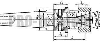
Correct installation of a conical part
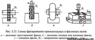
As long as the taper shank size matches the spindle diameter, installing the router bit on the router is a fairly simple procedure. The cutter is inserted into the spindle and secured with a tightening screw. This simplest and most effective method is suitable for machines with a horizontal or vertical spindle. This combination ensures quick tool changes. To install a cutter with a smaller shank diameter than the spindle, specialists use special bushings.
Vices and fixtures with key
If your T-slots are correct, you can install wrenches on the bottom of the vise or mounting plates that line up with the T-slots. You can also install the wrenches in T-slots that line up with the edge of the vise plate or base. This can save you quite a bit of time pulling out vices and such, and it's not difficult, so it's definitely worth thinking about.
The problem is that these solutions will help with one dimension (usually the short table dimension is the Y axis and is perpendicular to the slots), but we still have the problem of positioning along the T-slot axis. .
Luckily, there is a better way - auxiliary mounting plates (also called mounting plates).
Mounting plates, tooling plates and modular fastening
Accessory fixture plates (also called fixture plates or tool plates) are plates that fit on top of a T-slot table to provide a new way to position and secure fixtures. A typical tool plate looks like this:
Typical mounting plate
Tooling plates typically use a pattern of holes that alternate between holes for precision locating pins and threaded holes for fasteners. If this mesh is positioned accurately (or even if it is not and the positions are precisely known), you have a very repeatable way to install the tooling on the plate. The locating pins ensure precise positioning to within 0.01. Imagine being able to install a vise on a separate mounting plate with mounting pins and mounting holes, the repeatability of this operation will be about 0.01. If all your fixtures can fit on the tooling plate, you can actually switch the machine to a new fixture configuration very quickly. Saving time allows you to quickly recoup the cost of such a system.
The vise can be installed on one of these plates within one or two minutes. A CNC machine can be reconfigured in 5 or 10 minutes for a completely different job. In addition, the skill required of machine operators, as well as the likelihood of errors, are greatly reduced if fixtures do not have to be carefully adjusted each time. There are also advantages to creating modular G-code because it can rely on a positioning grid.
If accuracy greater than 0.01 is required, it is often better to use probing along with the selected g-code parameterization to correct the remaining error. You can try to fine-tune the parameters manually, but the probing solution may rely on everything being nearly correct to determine the last little bit of error correction that needs to be applied in the g-code itself. For example, you can very accurately apply rotation to g-code based on sensor output (aligning objects to axis motion).
Tool plates are usually made of cast iron or aluminum, although steel plates are also available. They can be purchased or made from scratch. For a complete guide, be sure to visit our page on mounting plates.
Devices for installing and securing workpieces on milling machines.
Universal devices (clamps, corner plates, prisms, machine vices, etc.) are designed for securing workpieces. They are used mainly in single and small-scale production.
Clamps are used to secure workpieces of complex shapes or large dimensions directly on the machine table. In Fig. Figure 1 shows different types of clamps: tile (Fig. a), fork-shaped (Fig. b), trough-shaped (Fig. c), curved universal. All clamps have oval holes or recesses to move the clamp relative to the workpiece being processed. In Fig. 2, a shows the fastening of the workpiece being processed on the machine table with a tile clamp, which rests on the workpiece at one end and on the lining at the other. The bolt head fits into the T-slot. table through the clamp hole. When tightening the nut with a wrench, the clamp is pressed against the workpiece, securing it. Stepped supports (Fig. 2, b), various bars of the required height, or special supports for tile clamps (Fig. 2, c) are used as a lining for the clamps.
Rice. 1. Tacks
Workpieces of small heights can be fixed directly on the machine table with clamps (Fig. 20, d and e). In some cases, it is convenient to use a spring-loaded clamp with a fairly large range of reach adjustment and securing the workpiece with a handle. The height-adjustable curved universal clamp is very convenient to use (Fig. 2, e).
Rice. 2. Securing the workpiece on the machine table
Workpieces of different heights can be secured with universal clamps. In the clamp shown in Fig. 3, a, the workpiece is secured with an L-shaped clamp with a recess into which the cracker is installed. The workpiece is secured with a bolt and nut. The stepped clamp (Fig. 3, b) consists of a housing in which there are ledges (steps) located along the recess of the housing at different heights. The lining rests on the ledges, inserting its slot into the slot of the clamp, and is pressed against it by a spring. The clamp can be turned over 180°. The clamp body has a through threaded hole for the clamp bolt and for attaching the entire clamp to the T-slots of the machine. The clamp allows you to secure workpieces of different heights within a certain range.
When finishing milling, tightening the bolts should not cause deformation of the workpiece.
Corner plates are used for installation and fastening of workpieces having two planes located at an angle of 90°. In Fig. 5, and a conventional corner slab is shown. It has one or two stiffening ribs and two shelves (equal or unequal, wide or narrow), located at an angle of 90°. In Fig. 5, b shows a rotating corner plate, the shelf of which can be rotated around its axis after releasing the nut and set to the required angle on the scale. Such plates are used when processing inclined planes.
Rice. 4. Universal clamps
Rice. 5 Corner slabs
In Fig. 5, c shows a universal corner plate that allows rotation of a fixed workpiece in two planes: horizontal - with handle I and vertical - by turning a block secured with bolts. The plate is a rotary table with three T-shaped slots. The angle of rotation of the table is measured on a scale.
In Fig. Figure 5 shows the fastening of a long and wide but thin strip to a corner slab with clamps. To ensure proper installation of the corner plate on the table, its base has a tenon that fits into the groove of the table.
Before fixing the workpiece on the corner plate, you must carefully check the correct installation of the plate itself on the machine table using a thickness gauge or indicator.
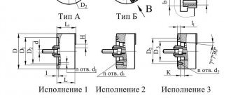
By design, machine vices are divided into simple, rotary and universal. In Fig. 7 shows a machine vice with a manual clamp. They are a simplified modification of pneumatic machine vices with a high degree of modification (80%). To power the hydraulic drive of machine hydraulic or pneumatic vices, an individual hydraulic station of the GMT type or a pneumatic-hydraulic converter of the PMT type, operating from the factory pneumatic network, is used. The use of special removable jaws and pads for machine vises leads to a significant reduction in the time spent on installing workpieces. In Fig. 8 shows several examples of designs of replaceable jaws for securing workpieces (a - with inclined planes; b - processed along the outer planes and ends; c, d - shafts). Such sponges can be made, if necessary, for any workpieces being processed.
Rice. 6. Securing the workpiece on the corner plate
Rice. 7. Machine vice with manual (pneumatic) clamp
Hydraulic and air-hydraulic vises provide greater clamping force than pneumatically driven vises. In Fig. 26 shows a hydraulic rotary vice, the feature of which is the simultaneous movement of both jaws, ensuring self-centering of the part. The workpieces are secured under an oil pressure of 4900 kPa supplied from the hydraulic system of the machine or from a separate pump unit into the base cavity. Under oil pressure, the piston moves down, and the levers, turning around their axes on the screws, press both jaws to equal distances. To install and secure workpieces or special overlays, T-shaped grooves are provided on the upper and side planes of the jaws. Preliminary adjustment of the vice is done with screws. The ability to rotate the body relative to the base 9 allows you to process workpieces with rotation around an axis within 360° with an accuracy of 1° on the scale. The mechanized stroke of the movable jaws in this vice is 24 mm. When adjusting, the jaws are moved apart from 0 to 200 mm. The clamping force at the specified oil pressure reaches 53955 N.
Recently, devices with barium oxide magnets have begun to be used to secure steel and cast iron workpieces with a flat supporting surface. Devices with barium oxide magnets have a number of advantages compared to previously used magnetic devices, namely: there is no residual magnetism in the fixed workpieces, the metal-cutting tool is not magnetized, non-scarce materials are used for the manufacture of such devices.
Rice. 8. Replacement jaws for machine vices
Rice. 9. Hydraulic self-centering rotary vice
Rice. 10. Device with barium oxide magnets
Rice. 11. Installing a vice on the milling machine table
Magnetic vices can be installed using keys (crackers) inserted into the groove in the base of the vice. These keys are inserted into the middle groove of the machine table. Screwing the nuts of the clamping bolts is done gradually. Over-tightening one nut and then all the others can cause the vise to become misaligned. The vice can be installed directly on the milling mandrel. The jaws of the vice are installed parallel to the axis of the milling mandrel. In this case, the mandrel is brought into contact with the stationary jaw of the vice and then the nuts of the clamping bolts are tightened. In Fig. Figure 11, b shows the installation of a vice for the case when the jaws are located perpendicular to the axis of the milling mandrel. A square is fixed in the jaws of the vice, which is pressed against the milling mandrel with its free shelf. To avoid deformation of the mandrel, it is necessary to use a feeler gauge, which is inserted between the milling mandrel and the fixed jaw or free flange of the square. If installed correctly, the dipstick can be pulled out with little effort.
Rice. 12. Alignment of the workpiece when installing it in a vice
Alignment of workpieces processed in a vice. Simultaneously with securing the workpiece, the correctness of its position is checked and installation errors are corrected. The correct installation of the workpiece in the vice in relation to the machine table is checked with a thickness gauge. For more accurate installation of the workpiece, an indicator with a stand is used instead of a thickness gauge.
When using various removable pads for the vice, the process of installing the workpiece is simplified and, in some cases, subsequent alignment is not required. A tight fit of the lower plane of the workpiece to the lining is achieved by tapping with a copper or brass hammer. Before securing workpieces with already machined surfaces in a vice, it is necessary to remove any burrs formed during the previous transition, if they may interfere with the correct installation or fastening of the workpiece. The jaws of the vice should be covered with covers made of sheet copper, brass or aluminum to protect the treated surfaces from dents. In addition, it is always necessary to sweep away chips from the table, workpiece supporting surfaces, clamping devices, vices, and pads before processing. Thin-walled workpieces of low rigidity should not be clamped with great force to avoid their deformation and, consequently, distortion of size and shape after processing.
In large-scale and mass production, special devices for installing and securing a specific part are widely used. Securing workpieces in special devices not only reduces the time for their installation and alignment, but also ensures higher processing accuracy. The pneumatic system must be operationally tested for air leaks. The same must be done for hydraulic clamps.
Universal devices (clamps, corner plates, prisms, machine vices, etc.) are designed for securing workpieces. They are used mainly in single and small-scale production.
Clamps are used to secure workpieces of complex shapes or large dimensions directly on the machine table. In Fig. Figure 1 shows different types of clamps: tile (Fig. a), fork-shaped (Fig. b), trough-shaped (Fig. c), curved universal. All clamps have oval holes or recesses to move the clamp relative to the workpiece being processed. In Fig. 2, a shows the fastening of the workpiece being processed on the machine table with a tile clamp, which rests on the workpiece at one end and on the lining at the other. The bolt head fits into the T-slot. table through the clamp hole. When tightening the nut with a wrench, the clamp is pressed against the workpiece, securing it. Stepped supports (Fig. 2, b), various bars of the required height, or special supports for tile clamps (Fig. 2, c) are used as a lining for the clamps.
Rice. 1. Tacks
Workpieces of small heights can be fixed directly on the machine table with clamps (Fig. 20, d and e). In some cases, it is convenient to use a spring-loaded clamp with a fairly large range of reach adjustment and securing the workpiece with a handle. The height-adjustable curved universal clamp is very convenient to use (Fig. 2, e).
Rice. 2. Securing the workpiece on the machine table
Workpieces of different heights can be secured with universal clamps. In the clamp shown in Fig. 3, a, the workpiece is secured with an L-shaped clamp with a recess into which the cracker is installed. The workpiece is secured with a bolt and nut. The stepped clamp (Fig. 3, b) consists of a housing in which there are ledges (steps) located along the recess of the housing at different heights. The lining rests on the ledges, inserting its slot into the slot of the clamp, and is pressed against it by a spring. The clamp can be turned over 180°. The clamp body has a through threaded hole for the clamp bolt and for attaching the entire clamp to the T-slots of the machine. The clamp allows you to secure workpieces of different heights within a certain range.
When finishing milling, tightening the bolts should not cause deformation of the workpiece.
Corner plates are used for installation and fastening of workpieces having two planes located at an angle of 90°. In Fig. 5, and a conventional corner slab is shown. It has one or two stiffening ribs and two shelves (equal or unequal, wide or narrow), located at an angle of 90°. In Fig. 5, b shows a rotating corner plate, the shelf of which can be rotated around its axis after releasing the nut and set to the required angle on the scale. Such plates are used when processing inclined planes.
Rice. 4. Universal clamps
Rice. 5 Corner slabs
In Fig. 5, c shows a universal corner plate that allows rotation of a fixed workpiece in two planes: horizontal - with handle I and vertical - by turning a block secured with bolts. The plate is a rotary table with three T-shaped slots. The angle of rotation of the table is measured on a scale.
In Fig. Figure 5 shows the fastening of a long and wide but thin strip to a corner slab with clamps. To ensure proper installation of the corner plate on the table, its base has a tenon that fits into the groove of the table.
Before fixing the workpiece on the corner plate, you must carefully check the correct installation of the plate itself on the machine table using a thickness gauge or indicator.
By design, machine vices are divided into simple, rotary and universal. In Fig. 7 shows a machine vice with a manual clamp. They are a simplified modification of pneumatic machine vices with a high degree of modification (80%). To power the hydraulic drive of machine hydraulic or pneumatic vices, an individual hydraulic station of the GMT type or a pneumatic-hydraulic converter of the PMT type, operating from the factory pneumatic network, is used. The use of special removable jaws and pads for machine vises leads to a significant reduction in the time spent on installing workpieces. In Fig. 8 shows several examples of designs of replaceable jaws for securing workpieces (a - with inclined planes; b - processed along the outer planes and ends; c, d - shafts). Such sponges can be made, if necessary, for any workpieces being processed.
Rice. 6. Securing the workpiece on the corner plate
Rice. 7. Machine vice with manual (pneumatic) clamp
Hydraulic and air-hydraulic vises provide greater clamping force than pneumatically driven vises. In Fig. 26 shows a hydraulic rotary vice, the feature of which is the simultaneous movement of both jaws, ensuring self-centering of the part. The workpieces are secured under an oil pressure of 4900 kPa supplied from the hydraulic system of the machine or from a separate pump unit into the base cavity. Under oil pressure, the piston moves down, and the levers, turning around their axes on the screws, press both jaws to equal distances. To install and secure workpieces or special overlays, T-shaped grooves are provided on the upper and side planes of the jaws. Preliminary adjustment of the vice is done with screws. The ability to rotate the body relative to the base 9 allows you to process workpieces with rotation around an axis within 360° with an accuracy of 1° on the scale. The mechanized stroke of the movable jaws in this vice is 24 mm. When adjusting, the jaws are moved apart from 0 to 200 mm. The clamping force at the specified oil pressure reaches 53955 N.
Recently, devices with barium oxide magnets have begun to be used to secure steel and cast iron workpieces with a flat supporting surface. Devices with barium oxide magnets have a number of advantages compared to previously used magnetic devices, namely: there is no residual magnetism in the fixed workpieces, the metal-cutting tool is not magnetized, non-scarce materials are used for the manufacture of such devices.
Rice. 8. Replacement jaws for machine vices
Rice. 9. Hydraulic self-centering rotary vice
Rice. 10. Device with barium oxide magnets
Rice. 11. Installing a vice on the milling machine table
Magnetic vices can be installed using keys (crackers) inserted into the groove in the base of the vice. These keys are inserted into the middle groove of the machine table. Screwing the nuts of the clamping bolts is done gradually. Over-tightening one nut and then all the others can cause the vise to become misaligned. The vice can be installed directly on the milling mandrel. The jaws of the vice are installed parallel to the axis of the milling mandrel. In this case, the mandrel is brought into contact with the stationary jaw of the vice and then the nuts of the clamping bolts are tightened. In Fig. Figure 11, b shows the installation of a vice for the case when the jaws are located perpendicular to the axis of the milling mandrel. A square is fixed in the jaws of the vice, which is pressed against the milling mandrel with its free shelf. To avoid deformation of the mandrel, it is necessary to use a feeler gauge, which is inserted between the milling mandrel and the fixed jaw or free flange of the square. If installed correctly, the dipstick can be pulled out with little effort.
Rice. 12. Alignment of the workpiece when installing it in a vice
Alignment of workpieces processed in a vice. Simultaneously with securing the workpiece, the correctness of its position is checked and installation errors are corrected. The correct installation of the workpiece in the vice in relation to the machine table is checked with a thickness gauge. For more accurate installation of the workpiece, an indicator with a stand is used instead of a thickness gauge.
When using various removable pads for the vice, the process of installing the workpiece is simplified and, in some cases, subsequent alignment is not required. A tight fit of the lower plane of the workpiece to the lining is achieved by tapping with a copper or brass hammer. Before securing workpieces with already machined surfaces in a vice, it is necessary to remove any burrs formed during the previous transition, if they may interfere with the correct installation or fastening of the workpiece. The jaws of the vice should be covered with covers made of sheet copper, brass or aluminum to protect the treated surfaces from dents. In addition, it is always necessary to sweep away chips from the table, workpiece supporting surfaces, clamping devices, vices, and pads before processing. Thin-walled workpieces of low rigidity should not be clamped with great force to avoid their deformation and, consequently, distortion of size and shape after processing.
In large-scale and mass production, special devices for installing and securing a specific part are widely used. Securing workpieces in special devices not only reduces the time for their installation and alignment, but also ensures higher processing accuracy. The pneumatic system must be operationally tested for air leaks. The same must be done for hydraulic clamps.
Ball locks and other solutions for quick tool insert changes
By now I hope you can see how much setup time you can save by using tooling plates. What could be better? There are at least two different ways to make setting up fixtures and accessories even easier: quick-change tool plates and trays.
With the Quick Change system, the time required to handle locating pins and fasteners is reduced with some kind of integrated solution that allows for precise positioning and very fast locking. One of them is the ball lock system:
Ball lock system
Ball locks are a system for quickly removing and installing tool plates. This system provides precise positioning and secure retention with 4 ball locks. Simply align the plate with the accessory plate (which has receiver bushings and is mounted on the table), drop the retainer ball shanks into the hole, tighten the bolt on top of the retainer ball shank, and you're done. It's really quick and easy to install four bolts without fiddling with locating pins or additional fasteners. We are talking about a 30-second changeover time, which is really very fast.
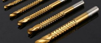
Features of the cutting element
Each type of replacement cutter has its own shape and size. The method of its installation may also depend on this. So the attachment type of element has a hole for putting on the router. End mills have a shank in their design. This tool has a small diameter. All sizes of replaceable consumable parts are standardized according to GOST.
Pallets
The next step is pallets. It's like automatic tool plates when everything else was manual. A typical pallet machine allows you to adjust one while the machine is working on another. Changing the pallet occurs by removing the old pallet outside the milling zone of the machine and installing a new one. This minimizes the amount of time the machine must be idle and allows adjustments to be made in parallel with processing.
Some machines have what are called "pallet pools", which allow you to set up multiple pallets in advance and schedule them to run. A pallet pool can allow a machine to run unattended for quite some time and can be a useful part for full automation.
Pallets are typically only seen on horizontal machining centers and some high-performance vertical machining centers. This is a full production feature that is quite expensive, so the cost needs to be justified.
4th axis, journals and tool columns
Sometimes it is useful to be able to apply another dimension to our thinking - in this case, the 4th Axis. In CNC, the 4th axis is usually the rotary axis. It is aligned to rotate along an axis parallel to one of the other three axes of the machine. On vertical machines, the 4th axis is often parallel to X or Y and routed downwards. On horizontal ones, the 4th axis is also parallel to X or Y, but it is vertical.
From a workplace perspective, the 4th axis can be used to introduce new orientations for two purposes:
1. It allows access to more sides of the part so processing can continue without the need to turn parts over by hand.
2. This allows access to more parts that can be positioned around the 4th axis.
To learn more about these applications, check out our excellent 4th Axis Basics series.
Devices and equipment. Working solutions
Having figured out how we are going to place and attach our attachment to the milling machine, let's look at what types of attachment there are in principle.
Milling vice
Pair of milling vicesOLYMPUS DIGITAL CAMERA
Today, the most popular solution for fixing workpieces is a vice. There are many manufacturers of these vises, a notable example being Kurt, who produced the first vises in the 1950s.
For a more detailed description of the machinist's vice, see our Complete Guide to the Vise. It's full of useful information.
Clamps, accessories and fixtures for plates
As useful as vices are, they do have their drawbacks. They have a hard time working with really large plates, although as mentioned, you can move the jaws to the extreme position for medium-sized plates. And they may also not be optimal for very small parts. Of course, you can place multiple parts in an array, but this is often inconvenient.
It's difficult to get small parts to fit so tightly with a vise, but the plate jig makes it easy. Mitee Bite Pit Bull clamps are used here. The effect is not unlike a tiny milling vice that fits every part perfectly.
When it comes time to handle large sheets or a lot of small parts, it's usually time to take the vise off the table and use clamps.
Step clamps
The most common type of clamp is called step clamp because it has small steps machined into it. They are typically used with T-slots, although you can also bolt them into the tool plate. Here are some typical stepped clamps:
The step clamp pressure plate, the step block supporting end of the clamp, and the bolt pass through the T-slot nut
Step Clamp Set
The photo shows a typical set of stepped clamps. It may be handy to stock up on an extra set so you have more clamping parts to work with. By stacking stepped blocks on top of each other and using longer bolts, you can clamp fairly tall workpieces. When using stepped clamps, keep the bolt close to the workpiece rather than the stepped block. It may be helpful to tilt the clamp onto the piece, raising it a step or two from level. You can also place a pad of soft material between the clamp and the workpiece to prevent damage to the workpiece.
Clamping blocks
Step clamps grip the top of the workpiece, which is sometimes inconvenient because you may need to machine the captured area. Toe clamps grip the side of the workpiece, allowing full access to the top of the workpiece. Many different types available:
This toe clamp moves the clamp down the ramp as it is tightened to press against the workpiece
These Mitee Bite Edge clamps have an eccentric bolt head that forces the hex against the workpiece as you tighten it.
Double-sided tape, glue, wax and low melting point alloys
Some workpieces are very difficult to hold because they are thin or because of their shape. As a rule, it is simply impossible to clamp them. Solutions for these situations include double-sided tape, glue, wax, and low melting point alloys.
The glue should be something that is released when needed. For example, Super Glue releases at a certain temperature, as does LocTite. The fumes from it are toxic, so try to remove them with good ventilation. Double-sided tape works great, especially for very thin materials.
Wax and low melting point alloys (usually bismuth alloys). They can be used to build up the workpiece and create a gripping zone. When processing is complete, the wax or alloy can be melted and stored for reuse.
Vacuum devices
Do you need to apply even pressure to hold the part? It can generate significant holding force given sufficient surface area. And it doesn't depend on the shape or how thin the material is. We have a good article on how to make your own vacuum attachments.
Perhaps the biggest disadvantage of vacuum tools is that their clamping force is limited by the surface area. Because of this, small parts can come off relatively easily. When the cutting forces exceed the clamping force that the vacuum table can provide, the part will pop out and deteriorate. This is a common problem for vacuum table users. This is especially true for small parts that do not have a large surface area.
Chucks and collets: for round parts
Typically round parts are machined on lathes, although in many cases milling may be required. If you have a lathe/mill, it may not be necessary to put it on a milling machine. But if you just need to work on some round parts on the router, you can use the same fasteners as for lathes. Simply bolt them on or press them against the mill table. For example, use a three-jaw chuck or a collet chuck set.
Lathe chucks are especially common on 4-axis because we often start with a round workpiece.
From time to time we put round pieces on the table because it's much faster. Consider this setup for processing round parts:
4-axis installation
I would never have thought, but many experts say that this 4-axis setup is very effective. It was capable of cutting aluminum rods to length, providing square edges, and drilling and tapping holes faster than a lathe.
Expansion mandrels, mandrels and studs
We can use expansion mandrels, mandrels or studs. The idea is to place the flared cylinder into a hole on the underside of the workpiece. This will secure the workpiece in place. So, you can access the workpiece from all sides except the bottom. This way, you won't collide with the support being processed (you need to remember where the mandrels are so you don't have one in the middle of the pocket!).
Here's a fixture using flared studs:
Turning the bolt spreads the pin apart to allow the workpiece to be clamped
There are many similar devices available to suit your needs. These are especially common for lathes, but as we already mentioned, you can use a lathe tool at work if you can find a way to secure it to the table.
Installation of cutters
The simplest method is to directly install the cutter on the spindle and clamp it with a nut. The direction of the thread must be opposite to the direction of rotation of the spindle.
Chucks are used to install end mills on the spindle. Backed cutters are secured with a shank in a collet chuck. Single-cut, non-backed cutters are secured in special chucks with a screw.
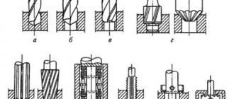
When directly seated on the spindle (Fig. a
) cutter 3 rests against the shoulder of spindle 7 and is clamped with nut 5. To change the height position of the cutter, spacer rings 2, spacers or washers 4 are used.
If the diameter of the mounting hole is larger than the diameter of the spindle, use a landing on the spindle through a bushing (Fig. b
). The cutter is first secured to sleeve 1 with nut 2, and then the sleeve is installed on the spindle and secured with a tightening nut.
In the case where the spindle does not have a thread for attaching a cutter, use a collet mandrel (Fig. c
). The mandrel has an inner conical split 1 and an outer 2 bushings. The cutter is installed on the outer sleeve and secured with a nut. Then the mandrel with the tool is installed on the spindle and secured by rotating the upper tightening nut. In this case, the outer bushing moves along the inner conical bushing, as a result of which its split part tightly covers the spindle.
Methods for attaching milling cutting tools to machine spindles:
a - direct landing; b - landing through a bushing; c - collet mandrel
If the machine spindle does not have axial adjustment movement, the cutter can be mounted in an installation head equipped with a device for adjusting the position of the cutter relative to the working surface of the table (Fig. d
). The position of head 2 with the cutter is adjusted with the inner sleeve loosened by rotating screw 1, which rests against the end of the spindle.
Standard fastening is common (Fig. e
) of the cutter head on a horizontal spindle with two short conical collets 3, clamped with nuts 1. Pins 4 in the head body fit into the slots of the collets, preventing their rotation. When screwed in, guide screw 2 fits into the keyway of the spindle and serves to fix the head and increase the reliability of torque transmission.
In foreign models of machine tools, hydroplastic devices for securing cutters on spindles have become widespread (Fig. e
). Thin-walled bushing 2 is pressed into the cutter body 3. The inner surface of the bushing is both centering and clamping. Hydroplastic 4 is injected into the cavity between the sleeve and the cutter under pressure. The pressure is created by rotating the plunger screw 5. To detach the cutter, the pressure in the cavity is reduced by unscrewing the screw 6. The fastening ensures increased accuracy of centering the cutter on the spindle 1.
Methods for attaching milling cutting tools to machine spindles:
g - in the installation head; d - two short conical collets; e - hydroplastic device; g - in a special eccentric chuck
Backed end mills are mounted in collet chucks, non-backed end mills are mounted in special chucks with eccentricity e
the axis of the hole for the tool relative to the axis of the chuck shank (Fig.
g
). The cutter 2 is held in the chuck body 3 by screw 1. The chuck shank 5 is installed in the tapered hole of the spindle 6 and tightened with a nut 4. The chuck body has six holes for screwing in balancing screws.
Author: Doctor of Technical Sciences, Professor V.V. Amalitsky