January 17, 2018
power managementautomationcritical applicationslab instrumentsInfineonarticlediscrete semiconductorsIGBT
Until now, in many industries there is no alternative to the application of protective and decorative coatings through galvanization . But the 21st century places new demands on flexibility and environmental friendliness of production, which is why the requirements for equipment that controls the electrical parameters of electroplating have increased. Fortunately, at the same time, an element base appeared that meets new requirements, in particular, Infineon IGBT modules .
Already at the dawn of the development of electroplating, a problem arose due to the fact that the coating process required direct current, while alternating current networks were being developed everywhere. At first, electroplating installations were powered by galvanic cells. Then, with the invention of mercury rectifiers at the beginning of the 20th century, it became possible to apply coatings by receiving energy from an alternating current network. Since then, the equipment that provides the specified power supply parameters for the galvanic bath is called a “rectifier” among electroplating specialists. Although now this is a much more complex device, which includes not only a voltage converter and, in fact, a rectifier, but also a stabilizer and some other components that provide additional functions (for example, timers). From the point of view of electrical engineering, such systems are correctly called “power supplies”. However, in this article we will use an already established term.
Each type of galvanic process and each coating material has its own electrical parameters. In some cases it is necessary to stabilize the voltage, in others it is necessary to stabilize the current density (the ratio of the current strength to the surface area of the product being coated).
The ability to adjust parameters in rectifiers based on semiconductor diodes was realized by switching taps from the transformer winding. At the same time, to ensure high quality coating, an additional voltage stabilizer was required at the input of the rectifier (ferroresonant, relay, electromechanical). More advanced thyristor rectifiers, which replaced diode rectifiers in the 60s of the 20th century, made it possible to smoothly adjust the parameters. It became possible to combine a rectifier and stabilizer in a single device. However, until the 2000s, it was common practice to supply industrial plants with rectifiers specifically designed for a specific galvanic process.
The global economic crisis of 2008 led to the fact that companies involved in electroplating began to incur losses. A solution was found in the creation of flexible production facilities that can adapt to the needs of a wide variety of customers [1]. As a result, rectifiers whose parameters can be quickly changed have become in demand in electroplating production.
At the time of writing, in Russia there was also an increase in interest in rectifiers for electroplating based on IGBT transistors, which is due to the policy of import substitution, as well as the desire of domestic enterprises to increase exports, which requires improving the quality and reducing the energy intensity of products.
Features of the design of a rectifier for electroplating
It is a common misconception that the design of a rectifier for electroplating is not much different from other types of power supplies. Since rectifiers for electroplating are expensive, you can find many descriptions on the Internet of how to make such a rectifier from a regular power supply. But such a solution is applicable only for amateur production of things in a single copy. In industrial production, it is possible to use only rectifiers specifically designed for electroplating. The reason for this is some features of the operation of such devices:
- Low output voltage (as a rule, it lies in the range of 6...48 V) combined with a high (up to 12000 A) current value. It is not surprising that the rectifier is often connected to the galvanic bath not by a cable, but by a busbar.
- The load resistance during operation can change several times.
- The specified current or voltage must be maintained at the output with an accuracy of no worse than 3%. This is necessary to ensure high quality coating (which is carried out in a certain optimal mode) and repeatability of serial production.
- Low level of pulsation at the output, since pulsations with frequencies of 50...300 Hz have a bad effect on the quality of the coating, especially when it comes to modern environmentally friendly technologies for galvanic deposition of nickel and its alloys.
- To obtain a more even surface, it is desirable to have a reverse mode, when you can periodically change the polarity of the connection to the bath with an interval of a few to tens of seconds.
- It is desirable to have a current limiting function at a user-specified level while stabilizing the voltage (if the current exceeds the specified value, the output voltage decreases).
The large power required for electroplating requires the rectifier to be powered from a three-phase network. An exception are rectifiers used in small repair shops, at craft enterprises, as well as at home by those who like to make something (precautions should be taken to ensure that harmful substances do not reach neighbors!).
What do we need
The power supply 1) reduces the voltage from 220 Volts to a small one and 2) rectifies it, i.e. turns a variable into a constant. “Plus” and “minus” in electroplating must be observed. Any network adapter can do this, for example, a mobile phone charger.
What else do we need? 3 - regulator, 4 - indicator. The regulator is a knob that we turn. The indicator shows the current strength. And all this farming in one building. So that wires and parts do not lie chaotically on the table, to the delight of children and the cat.
Environmental requirements
The accuracy of setting the current or voltage mode (depending on the process) helps reduce emissions of harmful substances. For example, when the optimal value of current density from a galvanic bath is exceeded, the intensity of the release of harmful substances increases significantly.
The current trend in the application of protective and decorative coatings is the transition from chrome plating to nickel plating, which is due to the need to protect the environment, since chromium is considered a more harmful material. The prevalence of chrome plating is associated with the ease of obtaining durable galvanic coating at the same technological level. Durable coatings with nickel and its alloys can be obtained using the technology of metal recovery from urea-based ionic melts. This process, as shown by research results [2], is sensitive to the voltage at the output of the rectifier. Depending on the potential difference, either pure nickel or a nickel alloy, or nickel or a nickel alloy contaminated with carbon is deposited. This requires high precision voltage stabilization. With this coating technology, the current-voltage characteristic of the galvanic bath may have a section with negative resistance, which places increased demands on the stability of the rectifier.
Rectifiers of the VAK and VAKR series.
VAK - (B) rectifier (A) automated (K) on silicon valves.
VAC rectifiers were widely used in electroplating shops in the USSR. There are still factories where these devices work properly. Thanks to the use of thyristors, the units have smooth regulation of rectified voltage up to 6/12/9/18/24/48 V and automatic stabilization of rectified voltage and current up to 100/320/630/1600/3200/6300/12500/25000 A. The stabilization accuracy is +/- 5%.
The appearance of the unit is similar to the VAKG.
Thyristor rectifiers
Rice. 1. Thyristor rectifier, made according to a direct circuit
Figure 1 shows the circuit of a simple three-phase thyristor rectifier. The abbreviation SIFU in the diagram means “Pulse-Phase Control System”. This system regulates and stabilizes voltage. This rectifier is built according to the so-called direct circuit, which does not provide for alternating current frequency conversion. The operating principle of thyristor rectifiers built according to this scheme is based on cutting off part of the sinusoid in the intervals between certain phase values (cut-off angles). As a result, only part of the electrical power is supplied to the output of the rectifier.
The output voltage graph for a thyristor rectifier is shown in Figure 2. The problem with thyristor rectifiers for electroplating (as, indeed, in the case of diode rectifiers used earlier) is that significant voltage ripple is observed at the output, at least 14%. It is almost impossible to smooth out ripple at the output using a choke, since very low voltages and high currents are used in electroplating. At a low ripple frequency (300 Hz when powered from a three-phase network with a frequency of 50 Hz), you will need a choke with a large number of turns, and therefore a large DC resistance, which is unacceptable. At the output of thyristor rectifiers, only high-frequency chokes with a small number of turns are installed, suppressing interference created by other devices.
Rice. 2. Voltage at the output of the rectifier (blue) and current at the input along one of the phases of the thyristor rectifier (green) without power corrector
Pay attention to the shape of the current consumed: it is far from a sinusoid. To obtain an acceptable power factor in rectifiers built according to a direct circuit, bulky correctors are used.
The disadvantage of thyristors is their inertia. When a control pulse is applied, a conductive zone first forms near the boundary of the control electrode and only then spreads across the area of the structure at a speed of 0.03...0.1 mm/s. During switching, the thyristor heats up. When the thyristor crystal is heated above 70°C, it may spontaneously operate without a control pulse. Therefore, thyristors require efficient heat dissipation. Due to complex cooling systems, thyristor rectifiers for electroplating are, as a rule, bulky devices made in the form of floor-standing cabinets (Figure 3).
Rice. 3. Placing thyristor rectifiers for electroplating in cabinets
At the same time, thyristor rectifiers for electroplating have some advantages. The technology has been well established for a long time, so servicing of such devices can be carried out on site by any specialist who knows how to repair power supplies for industrial applications.
Rectifiers with non-stepping current regulation.
To rectify the current in the first rectifiers until 1969, a diode bridge with copper-oxide diodes (cuproxy rectifiers) was used (Figure 1). In old galvanic shops, selenium rectifiers BC, VSA, VSG, WSMR with air and oil cooling, rated voltage 3.5/4.5/6/12V and current strength 100/200/300/600/1000/1200/2000 are sometimes used /2500/5000 A. These units have a common drawback - the lack of smooth adjustment of voltage and current density.
Figure 1 — Appearance of selenium rectifier VSA-3M
Adjustment of the rectified voltage is carried out by changing the voltage supplied to the selenium bridge using a regulator with a magnetic shunt. The shunt moves using a screw gear.
After selenium rectifiers, germanium rectifiers of the WAGG type were manufactured for voltages of 4.5/6/9/12V and currents of 600/3000/6000A.
Inverter rectifiers
It is possible to ensure a high power factor, low level of output ripple and high conversion efficiency by building a rectifier according to the inverter circuit shown in Figure 4. The electric current entering the input of the primary rectifier from the network is rectified and smoothed. The resulting direct current powers an inverter, which produces alternating current of a significantly higher frequency than the frequency of the current in the network. A compact high-frequency transformer is connected to the inverter. The current from the secondary winding of the transformer is supplied to the secondary rectifier, from where, through a smoothing choke, to the output of the device. You can smooth out ripple to a level of less than 3% at high frequencies using a choke with a small number of turns. By controlling the parameters of the inverter, you can stabilize the voltage or current at the output at a given level, as well as work out more complex programs, for example, stabilize the voltage until the current exceeds a specified value, and then reduce the voltage so that the current remains at a given limit level .
Rice. 4. Block diagram of a typical inverter rectifier
Until recently, thyristors were the main element base in the construction of powerful inverters. Thyristor inverters can operate at frequencies of no more than 3 kHz. Increasing the frequency at which the thyristor operates will require additional cooling compared to a frequency of 50 Hz. As a result, the inverter rectifier turns out to be even more bulky compared to a rectifier made according to a direct circuit.
A special feature of a thyristor compared to other power semiconductor devices is that it is turned on by a pulse supplied to the control electrode, but it turns off only when the voltage difference between the anode and cathode is less than a certain value. As a result, thyristor inverters have a narrow operating load range. For electroplating, this is unacceptable, since to improve the quality of the coating, it is recommended to lower the product being coated into a galvanic bath already under voltage, which leads to a change in the load on the rectifier over a wide range.
The listed problems have led to the fact that mass-produced models of thyristor rectifiers for galvanics are built only according to the direct circuit.
Volts and Amps
Don’t want to delve into how volts differ from amperes? We will not. Let's just decide how many we need. Just remember: voltage is volts, current (or simply “current”) is amperes.
1 amp = 1000 milliamps. 1A = 1000mA *With Latin and Russian letters, whether to write “Ampere” with a capital or small letter is a complete pandemonium, get used to it. mA is the same as mA . Volts V (in Russian) or V.
Good news: 2-3 Volts are enough for copper plating; any power supply will supply them without problems.
* Chrome plating and anodizing of aluminum requires relatively high voltages. These processes are clearly not for beginners, so we will focus on copper and nickel plating.
Second news: the required current depends on the area of the masterpiece being created. Approximately 20mA = 0.02 Ampere per square centimeter. For copper plating of one bead, earring, pendant or some small accessories, the current from any power supply is enough.
However, over time, appetites grow. For a bas-relief the size of a palm or for simultaneously freezing 10 large beads, the current strength begins to be insufficient - well, just like money in real life.
* A fist-sized wire lampshade required 4 Amps. Although its area (holes do not count) does not seem so large. At a current of 2A, not only the process speed is half as much as at 4A. You can live with this, but the coating turned out dull. At high current and with shine-forming additives in the electrolyte, the coating becomes shiny and mirror-like. Does not require any polishing or varnishing.
Application of IGBT
Rice. 5. An example of an IGBT rectifier capable of delivering current up to 1500 A
A more promising element base for inverter rectifiers are IGBTs. Here are their main advantages compared to thyristors:
- at least an order of magnitude shorter transition time from the “closed” state to the “open” state and back;
- the ability to create powerful inverters with an operating frequency of up to 30 kHz;
- good handling. Applying one voltage or another to the gate clearly causes the IGBT to open or close.
Quick switching from one state to another reduces the heating of the device. The high operating frequency of the inverter radically reduces the size of the transformer and chokes, which makes it possible to create compact rectifiers (Figure 5). Finally, good controllability makes it possible to create inverters that operate stably when the load changes over a wide range, which is very important for electroplating. The small size of the rectifier simplifies its protection from moisture and dust, which allows the rectifier to be located as close as possible to the galvanic bath. This makes more efficient use of the production workshop area and reduces the cost of busbar trunking.
A comparison of the characteristics of typical Russian-made rectifiers based on thyristors and IGBTs is given in Table 1.
Table 1. Characteristics of domestic rectifiers for electroplating powered by a three-phase AC 380 V network
| Name | HBA TE1-800/24T | IMP Gold UNIV-800A/12V | HBA TV1-1600/12T | NEON IPG-12/1500-380 |
| Element base | Thyristors | IGBT | Thyristors | IGBT |
| Cooling type | Vodyanoye | Forced air | Vodyanoye | Forced air |
| Output voltage, V | 2,4…24 | 0…12 | 0…12 | 1…12 |
| Output current, A | 80…800 | 0…800 | 160…1600 | 15…1500 |
| Efficiency, not less, % | 78 | 87 | 78 | 88 |
| Power factor, not less | 0,85 | No data | 0,85 | 0,86 |
| Ripple coefficient, % | No data | 2% | No data | 1 |
| Degree of protection | No data | IP32 | No data | IP54 |
| Dimensions, mm | 1000x600x1740 | 470x410x450 | 1000x600x1740 | 720x510x670 |
| Weight, kg | 440 | 41,5 | 470 | 120 |
Servicing IGBT rectifiers is more difficult than thyristor rectifiers. But the relatively low mass of the rectifier makes it possible to organize its delivery to a service center.
DIY power supply for electroplating
PCB Assembly from $30 + FREE Shipping Worldwide + Stencil
The webinar program includes: Silent Switcher® technology - a combination of high efficiency and ultra-low EMI levels, uModule® technology - highly integrated power supply solutions, micro- and nano-power DC/DC converters, backup power solutions, digital power system management (PSM), optocoupler-free isolated flyback converters. The practical part of the webinar will demonstrate examples of working with Analog Devices tools for designing power supplies.
| Attachments: |
| IMG_4965.JPG [75.02 KiB] Downloads: 2309 |
_________________ About how many wonderful discoveries the spirit of enlightenment is preparing for us.
“When a society has no color differentiation of pants, then there is no purpose!”
Connfly, one of Asia's leading manufacturers of standard connectors, and Compel, as part of a partnership program for warehouse development, are introducing installation panels for microcircuits. The DS1001-01 series sockets are made in a Dual In-Line housing and are designed for multiple placement and connection of DIP integrated circuits into electronic devices.
_________________ About how many wonderful discoveries the spirit of enlightenment is preparing for us.
“When a society has no color differentiation of pants, then there is no purpose!”
Best the enemy of the good .
_________________ Although optics magnify images, looking through an optical sight, all problems become smaller.
_________________ The invention and acquisition of RADIO is the greatest achievement of humanity, which has no equal.
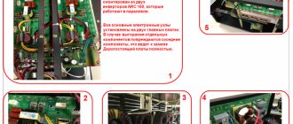
good day everyone, need forced me to make an installation for galvanization, the conditions are quite strict but not impossible, the reactor itself is ready but the question arose about the current source; there are two transformers from UPS each with two windings of 8.5 V, connected in series or in a circuit with a common one point which gives 16V at the output or so in parallel which gives us 8.5V
Let's start with everything about the power supply, let's talk about the current stabilizer. Before this, a thermally unstable linear stabilization circuit melted, of this kind, in fact, everyone understands that at a current above 20A it will heat up fiercely, which is what happened and what happened was that I had a local overheating of the transistors, they shorted out and there was a breakdown of the diodes in the rectifier
I had a strong desire to make a pulse stabilizer, but unfortunately my knowledge of electronics is not enough to make a PWM power supply or similar ones, I desperately ask for help
that's what you need: current stabilizer 1-30a 4.5v power supply 16 volts at the output voltage regulation is desirable but not required long-term operating mode current regulation is required load galvanic bath with resistance changing during the process must be able to hold a given current by changing the voltage pulse or similar in order to get rid of thermal unstable elements
_________________ Nothing strengthens mutual trust more than 100% prepayment! Dmitry, RK3AOR.
where is the processor power bus with low voltage mosfets? I repeat that I have poor understanding of microcontroller circuitry
I found a driver from Intel on the motherboard and this is the basic principle (see attachment) can you advise how to convert it to my needs?
| Attachments: |
| capture-20130109-231845.jpg [235.84 KiB] Downloads: 1847 |
_________________ Nothing strengthens mutual trust more than 100% prepayment! Dmitry, RK3AOR.
transformers 8.5 windings are made of copper wire, 2 squares of X3 wires, that is, 6 square windings
specialties are needed because the resistance constantly jumps during the process, and the process takes about a week (precipitation of salts), so it needs to be held by itself, and there is no latre available
_________________ Everything is not as it seems
I have two transformers but I doubt that I can connect them according to this scheme, one primary, two secondary at 8.5 they are connected with a common point like here
the load is turned on is also interesting, in fact the powder is easy to get, you can try it, I just wonder how long it will take to debug without an oscilloscope
The truth is that it immediately catches your eye that the author himself writes that at least 100 watts of heat will be dissipated by transistors, you will agree that this is a pretty big number, the radiators will turn out to be a whole barathea with airflow
_________________ Don’t interfere! WITH." Why doesn’t the Lord give us a helping hand for so long? And the worst thing is: maybe he’s holding out, but we don’t notice it longer and longer?”
_________________ Everything is not as it seems
I didn’t find the circuit diagrams of these models, a pulsed current source with current stabilization is enough for me, the circuit from the motherboard will do, all that remains is to decide how to control it, and come up with a two-layer signet, all the parts can be removed directly from the motherboard, although everything will be in the SMD with what it is connected a number of difficulties, and it will be difficult to catch errors without an oscilloscope
True, the stabilizer from the motherboard is a microscope, it’s not even nails, it’s an electronic microscope to chop stones
Last edited by Darknew Thu Jan 10, 2013 02:51:05, edited 2 times in total.
_________________ Nothing strengthens mutual trust more than 100% prepayment! Dmitry, RK3AOR.
Time zone: UTC + 3 hours
Who's on the forum now?
This forum is currently viewed by: no registered users and guests: 38
Selection of IGBT for rectifier
Let's consider the block diagram of the inverter rectifier shown in Figure 4. The primary rectifier is made according to the Larionov scheme, as the most efficient. The DC voltage at the rectifier output is calculated using formula 1:
$$U_{в}=\sqrt{2}\times U_{lin}=537\hspace{0.25em}В,\qquad{\mathrm{(}}{1}{\mathrm{)}}$$
where 380 V is the linear supply voltage.
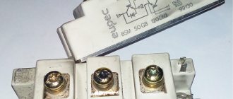
To build an inverter converter we will use a bridge circuit. For this we need 4 IGBTs. The maximum voltage values with which the IGBT can operate form a series of fixed values. Taking into account all the necessary voltage reserves, we will select a value of 1200 V.
It should be borne in mind that the maximum current at the output of the secondary rectifier will be several to tens of times greater than the current flowing through the IGBT, since there is a step-down transformer after the inverter.
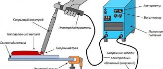
Because electroplating is a highly specialized field, IGBT manufacturers do not always make specific recommendations about what from their range can be used for a given application. However, the operating mode of the IGBT in a rectifier for electroplating is approximately the same as in an inverter welding machine: high power, low voltage, high current, changing load parameters. From this it follows that if a manufacturer does not separately highlight products for electroplating in its assortment, then it is necessary to choose the fastest IGBTs intended for welding machines.
Let's consider IGBT modules as the basis for building an inverter converter. IGBT switching losses increase as the chip temperature increases. When overloaded, the IGBT module heats up and losses increase even more. To prevent rectifier failure, temperature sensors are installed on IGBT modules (many modules already have them built-in). If a certain temperature value is exceeded, the rectifier turns off until it cools down completely. The part that is in the galvanic bath at this time, as a rule, goes to waste.
From a reliability point of view, the best option for electroplating is IGBT modules manufactured by Infineon Technologies, based on IGBT4 technology. A unique feature of the IGBTs used in these modules is the normalization of switching losses at a maximum permissible chip temperature of 150°C. This allows the cooling system to be designed in such a way as to almost completely eliminate emergency shutdown of the rectifier due to overheating of the inverter elements.
Other advantages specific to the IGBT4 series are high speed and low switching losses. This was achieved through the use of proprietary TrenchStop technology. In such a transistor, the drift N-zone is made in the main plate, which has the required thickness and doping level, and the thin N+ buffer layer, the lower P+ emitter and the upper MOSFET structure are implemented by local doping with precisely maintained optimal parameters. This structure became possible thanks to new technological solutions that made it possible to work with silicon wafers with a thickness several times smaller than the thickness of standard substrates [3]. In addition, the use of doping instead of epitaxial growth reduced the technological scatter, which made it possible to normalize the parameters at elevated temperatures.
Rice. 6. EconoDual 3 housing provides increased thermal conductivity
Within the IGBT4 series, the E4 modification has the highest performance. By the way, it is recommended by the manufacturer for welding machines, that is, it can also be used in rectifiers for electroplating. It is preferable to use the option in the EconoDUAL 3 housing (Figure 6), as it has improved heat dissipation and a built-in temperature sensor, which increases the reliability of the system. In addition, this housing has a low parasitic inductance of the elements, which is important for a powerful inverter.
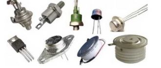
Often, designers of rectifiers for electroplating use discrete IGBT transistors, and there are objective reasons for this: ease of board routing, the ability to use old production lines, and reduced repair costs when only one transistor fails. For such cases, Infineon offers a series of high-speed discrete IGBT transistors with TrenchStop technology in a wide range of packages: from standard SMD DPAK and D2PAK packages to three- and four-terminal TO-220 and TO-247.
A simple electroplating power source from a computer power supply
The article discusses the design of a power source designed for use in electroplating. It is made on the basis of an ATX computer power supply and allows you to supply a stabilized current of up to 20A to the load for a time set using a timer.
The topic of amateur electroplating is quite popular. Electroplating technology requires a stable current source of fairly high quality. The use of medium-power amateur radio laboratory power supplies is not always acceptable for this purpose, since they usually try to balance the characteristics in such a way as to obtain a large output voltage range at a small current. On the other hand, all kinds of chargers for lead-acid batteries allow you to obtain a high current, often stabilized, but have poor output voltage quality, which does not allow you to obtain a smooth metal coating of the product.
Thus, the author decided to produce a specialized power source for use in electroplating (IG), which has the following main technical characteristics:
- mains supply voltage
230V;
- two interconnected channels with a continuously adjustable stabilized DC output voltage: in the first channel - from 0 to 20 V at a current of up to 10 A;
- in the second channel - from 0 to 8 V at a current of up to 20 A;
A lot of articles have been written about the modification of computer power supplies (BPSU), including by the author. A feature of this design is the use of a 5-volt output of the BPPK to obtain a large output current, a modified control and indication circuit, and the ability to connect a shutdown timer.
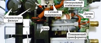
Description of the device circuit
The electrical circuit diagram of the IPG is shown in the figure. The IPG was based on a 300 W ATX power supply with a temperature sensor to control the rotation speed of the cooling fan. The original BPPK used a PWM controller of the DR-B2005 type, so an additional control board on the TL494 (DA3) controller was used to remake it. More information about such a replacement of a PWM controller can be read in the article “Converting computer power supplies with PWM controllers such as DR-B2002, DR-B2003, SG6105 into laboratory power supplies.” The control circuit is similar to that described in the article “Bipolar power supply - charger from a computer power supply.” To provide indication of the transition of the IPG to the current limiting mode, according to the recommendations given in the article by V. Andryushkevich “Converting a computer power supply into a laboratory and charger” (Radio - 2012, No. 3), a comparator DA2 was added to the control circuit, the output of which is loaded by LED HL2.
The circuit of the control circuit power supply module based on transformer T1 of the “standby” mode of the BPPK is similar to that described in the article “Conversion of computer power supplies with PWM controllers such as DR-B2002, DR-B2003, SG6105 into laboratory power supplies.” The original BPPK had a temperature sensor and the author decided to leave it, since automatic adjustment of the cooling fan speed significantly reduces noise. Therefore, an integrated stabilizer DA1 was added to the power supply circuit of the M1 fan, which supplies a stabilized voltage = 12 V to the thermostat.
The power supply module has two channels, since the 12-volt and 5-volt outputs of the T2 power transformer with the corresponding rectifiers are used. Using a 5-volt output allows you to get more current when needed than using a 12-volt output. The rectification and filtering circuits for both channels have no special features and correspond to the standard BPPK circuit. The current sensor Rш1 is connected to the common wire break, so it does not matter which channel is loaded, the current limitation will work in any case.
To indicate the level of output voltage and current, a widely used small-sized digital multimeter of the DT830V type was used, from which all standard dividers were removed, and the input circuit R6, R8, C7 was assembled, a decoupling capacitor C8, a shunt Rsh2 and an additional resistance R5 were installed. Measurements are made at a limit of 20V, which allows you to display the voltage and current value with two decimal places, that is, from 0.00 to 19.99. Using switch SA1, the voltage measurement channel is selected, and switch SA3 selects the type of work. The multimeter is powered by a separate stabilizer based on elements T3, VD5, VD10, C3, which is not galvanically connected to the rest of the circuit elements.
The IPG shutdown timer is based on the popular Chinese electronic-mechanical clock with an alarm clock. The clock is powered from the standby power supply BPPK through contact K1.1 of relay K1. The power circuit is a parametric stabilizer based on elements R4, HL1 with a stabilization voltage of about 2 V. Then this voltage is normalized to the nominal (about 1.5 V) using diode VD11 and filtered by capacitor C6. The capacitance of the capacitor is selected in such a way that the VD11 LED blinks while the clock is running, thus indicating its progress. Contact SA2 of the clock, which turns on the alarm signal, when closed, energizes relay K1, contact K1.1 opens, turning off the power to the control circuit and clock. Thus, the key transistors are not controlled and the voltage from the IPG output is removed.
Design, details and adjustment of IP
All elements of the IPG, except for the clock, are located in the BPPK case, in one of the sides of which a large hole is cut to accommodate the front panel with controls and indications. The clock is connected to the main unit through a connector located on the back wall of the IPG using a cable.
The individual functional blocks of the design are assembled either on separate printed circuit boards or by surface mounting. Printed circuit board drawings are not provided, as they underwent significant changes during the development process. In addition, the size and shape of the blocks will depend on the design of the original BPPK.
The rectifier diodes (diode assemblies) VD3, VD4 of the 12-volt circuit and VD7, VD8 of the 5-volt circuit were not changed, since the output voltage of the IPG does not exceed their maximum permissible parameters. In the original BPPK, to provide greater load capacity in the 5-volt circuit, two parallel-connected diode assemblies were installed: VD7, VD8 and VD6, VD9, one of which is sufficient and the second can be dismantled. Group stabilization throttle L1 is left unchanged. Filter capacitors C4, C5 were replaced in accordance with the ratings indicated in the diagram. You should also install load resistors R1, R2. The current sensor Rш1 is made of several parallel-connected pieces of brass wire with a diameter of 0.8 mm (previously served as a shunt of the old combined device) and is sealed into the common wire gap directly on the BPPK board.
You can take the design described here as the basis for the control unit board on TL494, adding a DA2 comparator to it. Details about setting up the control circuit are described in the original article by V. Andryushkevich. It is recommended to shunt the middle terminals of variable resistors R9, R12 to ground with capacitors with a capacity of 0.01-0.1 μF. It should be noted that to ensure more accurate adjustment of the current limit, it will be useful to add to the circuit and display on the front panel another variable resistor with a resistance 10 times less than R9, connected by a potentiometer to the gap in the wire connecting pin R9 to the common wire. By selecting resistor R11, the maximum voltage of the first IPG channel (0...20 V) is set, which is controlled by the control circuit. The voltage of the low-voltage channel (0...8 V) is regulated indirectly by monitoring the voltage of the first channel.
Remaking a DT830 type multimeter consists of shortening the printed circuit board to the smallest possible size and installing the necessary elements shown in the diagram. Depending on how you install the multimeter, you should also cut and shape its body. In this design, it was more convenient to move the multimeter outside the front panel, so the lower part of the case was carefully cut off and re-glued higher.
The watch's power circuit is located in the battery installation niche, with the HL1 LED displayed on the dial. The output of the SA2 alarm contact that goes into the clock circuit should be cut and a conductor connected to it. The second end of the contact is located on the minus of the clock power supply. The circuit located in the clock is connected to the main unit with a three-wire cable with an “audio” plug (TRS) installed at the end. This is convenient, as it allows you to easily replace the clock if it breaks down, or turn it off as unnecessary. A magnetic tape is glued to the base of the watch, with which it is securely attached to the body of the power source.
To switch the power supply to the control circuit, a small-sized relay K1 of the RES-15 type is used. Instead, you can use any other relay with one normally closed contact and a rated voltage of no more than 15 V. The current-limiting resistor R3 is selected experimentally to ensure normal operation of the relay under current. Instead of a relay, you can also use a low-power field-effect transistor with an insulated gate.
Shunts Rш1, Rш2 should be placed inside the case in such a way that they are well blown by a cooling fan, since they can dissipate a lot of power. The use of two shunts in the IPG design is due to the fact that the author used a previously manufactured and debugged multimeter and control board. In the new design, it is easier to use only a multimeter shunt, as was done in the design described in the article “Bipolar power supply - charger from a computer power supply.”
With the exception of previously described cases, there are no special requirements for the details of the device, and any available elements with parameters similar to the elements specified in the diagram can be used.
Concluding remarks
In addition to using IPG in the electroplating process, the presence of a shutdown timer in the described design makes it possible to automate other tasks, for example, charging batteries with a stable current for a given time.
Literature
- Elinek T.V. Advances in electroplating technology. Review of world specialized literature for 2008-2009 // Electroplating and surface treatment. 2010. No. 4, pp. 13…18;
- Babaskina S.Yu., Korbit A.A., Filimonov V.A., Yakubovskaya S.V. Nickel plating electrolytes based on urea melt // Creation of new and improvement of existing technologies and equipment for applying galvanic and their replacement coatings: materials of reports of the republican scientific and technical seminar. Minsk, BSTU, 2011, pp. 31...35;
- Popov A., Popov S. Infineon - the new leader in the IGBT market. Electronics News No. 8/2016.
•••
Power supply for electroplating
#1 S VICTOR S
- Gender: Man
- City: Planet Earth
Hello ! I would like to make myself a power supply for electroplating! Please share who has encountered this and prevailed, sensible links are also welcome. I’ll tell you right away there is no way to buy. THANK YOU!
#2 Zhenya-Zhenya
- Gender: Man
It depends on what V and A modes are required?
You can figure something out from a computer power supply. And practically for nothing.
*they made me a mini welding machine from a power supply from a computer!
#3 Jonik
#4 S VICTOR S
- Gender: Man
- City: Planet Earth
Hello. How is a power supply from a hundred amperes not enough to wake up? For a pencil it can handle it! but for refining, no it seems!!
#5 Jonik
Hello. How is a power supply from a hundred amperes not enough to wake up? For a pencil it can handle it! but for refining, no it seems!!
#6 S VICTOR S
- Gender: Man
- City: Planet Earth
Hello. How is a power supply from a hundred amperes not enough to wake up? For a pencil it can handle it! but for refining, no it seems!!
What does refining have to do with it? My Nokia charger covers it well at 0.5 ampere even in the bath.
Electrolytic refining is directly connected to the power supply! Thanks for charging from Nokia! I’ll try it. Isn’t the current in the charging pulsating by chance?
#7 Ashir
- Gender: Man
- City: Ashgabat
- Interests: I want to learn everything about jewelry making
*they made me a mini welding machine from a power supply from a computer!
Sorry, if possible, please tell me how this can be done and what do you use it for?
Selection of IP according to the degree of protection of the case
When choosing the degree of protection of the IP housing, its location should be taken into account. When located directly in the workshop near the galvanic line, the degree of protection should be chosen at least IP54 due to the presence of aggressive substances in the air and the possibility of splashes of reagents on the IP housing.
With a low degree of protection, this can lead to oxidation of the electronic components of the power supply and its failure. The key to reliable and trouble-free operation of the IP with this arrangement is timely maintenance and cleaning of cooling units (radiators, ventilation grilles and fans) from contaminants.
It is also possible to install a power supply directly in the workshop with a housing protection level lower than IP54, but only if the power supply is installed in a separate box with supply and exhaust ventilation, the parameters of which are higher in performance than the performance of the power supply cooling system. This installation method complicates the maintenance of the power supply and, if there are errors in the design of the ventilation system, can lead to failure of the power supply.
The most preferable, but at the same time expensive, method is to install the IP in a separate room. This arrangement ensures clean air in the room without aggressive components, easy access for maintenance and increases the service interval. But installation and operating costs also increase.
Technology
The power part of the electroplating sources consists of high-quality high-voltage IGBT transistors, which reduces weight and increases the efficiency of inverters by up to 90%. This high efficiency significantly reduces energy consumption and current load on the power supply network.
All sources for electroplating
STRAT can be used in various metal deposition processes and guarantee high accuracy and stability of output characteristics. The devices provide protection against short circuit, overheating and overload. All internal elements are well secured and protected by a durable metal case. The front panel contains: a digital display screen for the output parameter, an adjustment knob and cable sockets.