Field semiconductors
The MOSFET technology semiconductors used in inverters are field-effect power transistors with an insulated gate. The semiconductor is controlled by voltage, unlike bipolar transistors, which are controlled by current. The key channel has a high conductivity of 1 mOhm. When closed, they have a huge input impedance.
Initially, field-field semiconductors were and are still used as switches. In switching power supply circuits, field switches with an induced gate are used. In this design, at zero gate-source voltage, the channel is closed.
To open the key, a potential of a certain polarity must be applied. No power sources are required to operate the key. These semiconductors are often used in power supplies and inverters.
Which is better MOSFET or IGBT?
Some companies keep up with the times and in the production of welding inverters use American IGBT transistors, the switching frequency of which is 50 kHz, i.e. 50,000 times per second. IGBT technology was chosen for a reason, because their operating temperature range, while maintaining parameters, is much greater than that of MOSFETs, i.e. when heated, MOSFETs’ quality characteristics decrease.
The design of SAI (Resanta) uses one small board, which is installed vertically, as well as 4 IGBT transistors (they work separately from each other, i.e. they all do not burn out if one burns out like a MOSFET) and 6 rectifier diodes (not 12 like a MOSFET), respectively, the fault tolerance is lower. This is another “plus” of IGBT.
You can remind the buyer that modern welding inverters use only 4 individual transistors, and not 12 cascade-dependent ones like MOSFETs. Anything can happen in life, but no matter what happens if one transistor fails (if not a warranty case), a replacement will cost the buyer somewhere in the region of 400 rubles, and not 12 × 110 rubles. = 1320 rub. I think the difference is significant.
How to distinguish: Visually, IGBT devices mostly differ from MOSFETs in the vertical arrangement of power connectors, since there is only one board and is usually installed vertically. For MOSFET devices, the outputs are usually located horizontally, since the boards in the structure are horizontally fixed. It is impossible to say for sure that this is 100% true. More precisely, you can say by removing the casing from the device.
Many are transistorized. For example, it has currently launched devices on the market (using MOSFET technology) with stickers on the side panels “TOSHIBA transistors are used” and “Mitsubishi transistors are used.” They are trying to crawl out on loud and familiar brands. In practice this has not been confirmed. So at the largest International Instrumental Exhibition in Russia, Moscow International Expo (MITEX-2011), which took place in November 2011. at Expocentre (Moscow), I asked representatives of this company’s stand to disassemble their AIS with the sticker “Mitsubishi transistors are used” and demonstrate these transistors. As a result, the welding inverters were disassembled, but these transistors were not found. The employees themselves were shocked to discover unnamed transistors.
Bipolar device
IGBT is an insulated gate bipolar transistor used in inverter. In fact, it consists of two transistors on one substrate. The bipolar device forms a power channel, and the field one is a control channel.
The connection of two types of semiconductors allows you to combine the advantages of field and bipolar devices in one device. The combined device can, like a bipolar device, operate with high potentials; the channel conductivity is inversely proportional to the current, and not its square, as in a field-effect transistor.
In this case, the IGBT transistor has economical field device control. The power electrodes are called as in a bipolar device, and the control electrode is called a gate, as in a MOS device.
IGBT transistors for welding inverters and power drives, where they have to operate at high voltages, began to be used as soon as the technology for their production was debugged. They reduced the size, increased the performance and power of inverters. Sometimes they even replace thyristors.
In an IGBT inverter, to ensure the operation of powerful switches, drivers are used - microcircuits that amplify the control signal and accelerate fast charging of the gate.
Some models of IGBT transistors operate with voltages from 100 V to 10 kV and currents from 20 to 1200 A. Therefore, they are more often used in power electric drives and welding machines.
Field-effect transistors are more often used in pulsed sources and single-phase welding inverters. With current parameters of 400-500 V and 30-40 A, they have the best performance characteristics. But since IGBT devices can be used in more severe conditions, they are increasingly used in welding inverters.
general information
Transistors - what are they? Surely everyone who has ever encountered the repair or banal disassembly of radio electronics has heard this term. In simple terms, a transistor is an electronic part with terminals made of semiconductor material. The main function of a transistor is to amplify or generate electrical signals coming from outside. Switching is also performed using transistors.
At the moment, transistors are found in any electronic device and are one of the most important components. In the middle of the last century, several scientists received the Nobel Prize for the invention of the transistor. And since then, this small device has radically changed the world of electronics.
Transistors are very small and compact. They are economical and inexpensive to produce. Despite its modest size, the transistor is resistant to mechanical stress and durable. Transistors are also able to operate properly at low voltages and high currents. It was thanks to these advantages that by the end of the 20th century, transistors became an integral part of every electronic device. Including inverter welding machines.
Welding Application
A simple welding inverter is a switching power source. In a single-phase inverter power supply, alternating current with a voltage of 220 V and a frequency of 50 or 60 Hz is rectified using powerful diodes, the switching circuit is bridged.
Then the inverter converts direct voltage into alternating voltage, but at a high frequency (from 30 kHz to 120 kHz). Passing through a step-down high-frequency transformer (converter), the voltage drops to several tens of volts. This current is then converted back to direct current.
All transformations are necessary to reduce the size of the welding machine. The traditional welding inverter circuit turned out to be reliable, but had very large dimensions and weight. In addition, the characteristics of the welding current with a traditional power source were significantly worse than those of an inverter.
Transmission of electricity at high frequencies allows the use of small-sized transformers. To obtain a high frequency, direct current is converted using high-voltage, powerful power transistors into alternating current with a frequency of 50-80 kHz.
To operate powerful transistors, the 220 V voltage is rectified, passing through a bridge circuit and a filter of capacitors, which reduces ripple. An alternating signal from a square pulse generator is supplied to the control electrode of the semiconductor, which opens/closes the electronic keys.
The outputs of the power transistors are connected to the primary winding of the step-down transformer. Due to the fact that they operate at high frequencies, their dimensions are reduced several times.
Which is better MOSFET or IGBT?
Some companies keep up with the times and in the production of welding inverters use American IGBT transistors, the switching frequency of which is 50 kHz, i.e. 50,000 times per second. IGBT technology was chosen for a reason, because their operating temperature range, while maintaining parameters, is much greater than that of MOSFETs, i.e. when heated, MOSFETs’ quality characteristics decrease.
The design of SAI (Resanta) uses one small board, which is installed vertically, as well as 4 IGBT transistors (they work separately from each other, i.e. they all do not burn out if one burns out like a MOSFET) and 6 rectifier diodes (not 12 like a MOSFET), respectively, the fault tolerance is lower. This is another “plus” of IGBT.
You can remind the buyer that modern welding inverters use only 4 individual transistors, and not 12 cascade-dependent ones like MOSFETs. Anything can happen in life, but no matter what happens if one transistor fails (if not a warranty case), a replacement will cost the buyer somewhere in the region of 400 rubles, and not 12 × 110 rubles. = 1320 rub. I think the difference is significant.
How to distinguish: Visually, IGBT devices mostly differ from MOSFETs in the vertical arrangement of power connectors, since there is only one board and is usually installed vertically. For MOSFET devices, the outputs are usually located horizontally, since the boards in the structure are horizontally fixed. It is impossible to say for sure that this is 100% true. More precisely, you can say by removing the casing from the device.
Many are transistorized. For example, it has currently launched devices on the market (using MOSFET technology) with stickers on the side panels “TOSHIBA transistors are used” and “Mitsubishi transistors are used.” They are trying to crawl out on loud and familiar brands. In practice this has not been confirmed. So at the largest International Tool Exhibition in Russia, Moscow International Tool Expo (MITEX-2011), which took place in November 2011. at Expocentre (Moscow), I asked representatives of this company’s stand to disassemble their AIS with the sticker “Mitsubishi transistors are used” and demonstrate these transistors. As a result, the welding inverters were disassembled, but these transistors were not found. The employees themselves were shocked to discover unnamed transistors.
Source
You don’t need to have a 100% understanding of the intricacies of electrical engineering to express an opinion on a topic. The title " MOSFET or IGBT?" reminiscent of the old format competition: VHS or DVD? Who will win? And let them say that the comparison is not correct. But the DVD format is great, the sound and image quality are wonderful, and we are all so used to the good old VHS...
For those who do not understand what we are talking about, let us explain. Today, there are two manufacturing technologies for welding inverters,
A logical question arises: what to choose, old, time-tested, or relatively new, but more technologically advanced?
Let’s try to give a couple of arguments and, as they say, closer to the “body”...
Whatever you say, IGBTs occupy a smaller volume and at the same time allow for a higher output current, they heat up less. Isn't this an argument in favor of IGBT? The objections are that the IGBT circuits are not yet perfectly thought out, etc., the developers did not have time for this and they sound “tight”.
Of course, if you buy an inverter for household welding, then it is not so important what transistors it has inside. It doesn't really matter what's inside. The main thing is that the electrode ignites normally, the arc does not jump back and forth, so that the electrode does not stick. It is also desirable that the inverter operate at a reduced voltage in the network, without being afraid of voltage surges, so that the yellow overheating lamp rarely lights up.
If we are talking about small volumes of household work, then almost any inverter will become your reliable friend and comrade, the same Resanta or Svarog, or Fubag, or the domestic Fast and the Furious, etc. and so on.
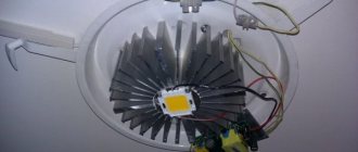
But what if you need a professional device, when you have to cook all day. In our opinion, IGBT is better here. Why? Let’s take the PICO 180 welding machine as an example—it’s a beauty, not a welder! Let's take its cooling system as an example. It is intelligent and turns on only when the transistors heat up. And in PICO, even after 15 or more minutes of welding at low currents, the fan does not budge. This means that the circuits are cold, the body of the device is cold. And all these are IGBTs; they heat up less intensely than MOSFETs and at higher currents. So what do I get from this, you say? Very simple. The less the fan runs, the better! Especially if you work in dusty areas. The main enemy of the inverter is dust. It is the main reason for the premature failure of inverters. Accordingly, the less dust is drawn into the welding machine, the better! This means that the longer the coolers are not turned on, the better! This can only be achieved with IGBT.
An undoubted advantage is also that high power is achieved with even lower weight. Every gram matters if you have to carry an inverter on your shoulder all day.
The downside at one time was the high cost of repairing IGBTs and the inability to sometimes find spare parts. But time passes, technology improves, and what was previously expensive and inaccessible becomes commonplace and easily replaceable! So our opinion is that the future lies with new technologies. And what do you think? Should we agree with this?
Today it is no longer a secret to anyone who won the “VHS or DVD” battle.
Source
Power inverter unit
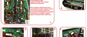
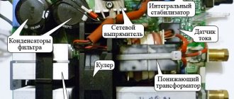
An alternating voltage of 220 V is some average value, which shows that it has the same energy as a direct current of 220 V. In fact, the amplitude is 310 V. Because of this, 400 V capacitors are used in filters.
The bridge rectifier assembly is mounted on the radiator. Cooling of the diodes is required because large currents flow through them. To protect the diodes from overheating, there is a fuse on the radiator; when a critical temperature is reached, it disconnects the bridge from the network.
Electrolytic capacitors with a capacity of 470 μF and an operating voltage of 400 V are used as a filter. After the filter, the voltage is supplied to the inverter.
When switching keys, pulsed current surges occur, causing high-frequency interference. To prevent them from penetrating the network and spoiling its quality, the network is protected with an electromagnetic compatibility filter. It is a set of capacitors and a choke.
The inverter itself is assembled using a bridge circuit. IGBT transistors with voltages from 600 V and currents corresponding to this inverter are used as key elements.
They are also mounted on radiators using special thermal paste. When these transistors switch, voltage surges occur. To suppress them, RC filters are used.
The alternating current obtained at the output of the electronic keys is supplied to the primary winding of a high-frequency step-down transformer. The output of the secondary winding produces alternating current with a voltage of 50-60 V.
Under load, when welding is in progress, it can deliver current up to several hundred amperes. The secondary winding is usually made with tape wire to reduce size.
At the output of the transformer there is another powerful diode bridge. The necessary welding current is already removed from it. Fast-acting power diodes are used here; others cannot be used because they get very hot and fail. Additional RC circuits are used to protect against surge voltages.
Which is better igbt or mosfet in a welding inverter
You don’t need to have a 100% understanding of the intricacies of electrical engineering to express an opinion on a topic. The title "MOSFET or IGBT?" reminiscent of the old format competition: VHS or DVD? Who will win? And let them say that the comparison is not correct. But the DVD format is great, the sound and image quality are wonderful, and we are all so used to the good old VHS...
For those who do not understand what we are talking about, let us explain. Today, there are two manufacturing technologies for welding inverters,
A logical question arises: what to choose, old, time-tested, or relatively new, but more technologically advanced?
Let’s try to give a couple of arguments and, as they say, closer to the “body”...
Whatever you say, IGBTs occupy a smaller volume and at the same time allow for a higher output current, they heat up less. Isn't this an argument in favor of IGBT? The objections are that the IGBT circuits are not yet perfectly thought out, etc., the developers did not have time for this and they sound “tight”.
Of course, if you buy an inverter for household welding, then it is not so important what transistors it has inside. It doesn't really matter what's inside. The main thing is that the electrode ignites normally, the arc does not jump back and forth, so that the electrode does not stick. It is also desirable that the inverter operate at a reduced voltage in the network, without being afraid of voltage surges, so that the yellow overheating lamp rarely lights up.
If we are talking about small volumes of household work, then almost any inverter will become your reliable friend and comrade, the same Resanta or Svarog, or Fubag, or the domestic Fast and the Furious, etc. and so on.
Soft start
To power the inverter control unit, a stabilizer is used on a microcircuit with a radiator. The supply voltage comes from the main rectifier through a resistive divider.
When the welding inverter is turned on, the capacitors begin to charge. The currents reach such high values that they can burn out the diodes. To prevent this from happening, a charge limiting circuit is used.
At the moment of starting, the current passes through a powerful resistor, which limits the starting current. After charging the capacitors, the resistor is switched off and shunted using a relay.
MOSFET or IGBT?
Let's look at the differences in general first. Currently, all inverter manufacturers (MMA) are produced using two semiconductor technologies: IGBT and MOSFET. I will not go into details, I will only say that the circuit design of these devices uses different semiconductor transistors IGBT and MOSFET. The main difference between these transistors is the different switching current. IGBT transistors have high current.
To make a standard inverter, you will need 2-4 IGBT transistors (depending on the duty cycle), and MOSFETs - 10-12, because they cannot pass large currents through themselves, so they have to be divided into such a large number of transistors. That's actually the difference.
The subtlety is that the transistors get very hot and need to be installed on powerful aluminum radiators. The larger the radiator, the greater the heat removal from it, and, consequently, its cooling capacity. The more transistors, the more cooling radiators need to be installed, therefore, the dimensions, weight, etc. increase. MOSFET definitely loses here.
In practice, MOSFET circuitry does not allow creating a device on one board: that is, the devices that are currently on sale are assembled mainly on three boards. IGBT devices always come on the same board.
Switching frequency
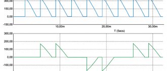
In Fig. Figure 7 shows diagrams of the process of switching on a MOSFET and IGBT module at a specific operating point. Without touching on the values of VDS/VCE and ID/IC, we note that the current value of power dissipation p(t) is determined by the product of the instantaneous values of current and voltage. The integral p(t) reflects the total dissipation power of the switch over a certain period of time, including losses on all transistors and diodes included in the module.
Rice. 7. The process of “hard” switching on and off on a resistive