First mentions
In the 700s AD. a unit was created that partially resembles a modern lathe. The story of its first successful launch begins with wood processing by rotating the workpiece. Not a single part of the installation was made of metal. Therefore, the reliability of such devices is quite low.
At that time, the lathe had low efficiency. The history of production has been reconstructed from surviving drawings and drawings. It took 2 strong apprentices to unwind the workpiece. The accuracy of the resulting products is low.
History dates information about installations vaguely reminiscent of a lathe to 650 BC. e. However, the only thing these machines had in common was the processing principle - the rotation method. The remaining nodes were primitive. The workpiece was literally set in motion by hand. Slave labor was used.
The models created in the 12th century already had some kind of drive and could be used to produce a full-fledged product. However, there were no tool holders yet. Therefore, it was too early to talk about the high accuracy of the product.
Who invented the caliper?
Screw-cutting lathe.
Caliper The caliper is the key component of a modern lathe; everything else could, to one degree or another, be borrowed from other mechanisms. At the same time, having a device for precise movement of a metal-cutting tool along the surface being processed, and in all three coordinates, one could talk about a fully functional machine for turning. But, as in most other cases from the history of technology, it is impossible to establish sole authorship in the invention of the caliper.
What does it say about Andrei Nartov’s priority?
Large lathe and copying machine built by Nartov in 1718-1729
- A self-propelled support appeared in Nartov's copying machine in 1712, while Henry Maudsley introduced his version only in 1797.
- For the first time, the joint movement of the copier and the support in the Nartov version of the machine was carried out using one mechanism - a lead screw.
- Changing the cross-feed speed was technically ensured by different thread pitches on the lead screw.
The term “support” (from the French word support - support) was first introduced into use by Charles Plumet, and the machine built by his compatriot Jean Vaucanson was practically similar to the one with which all turners now work.
This mechanism had V-shaped guides that were accurate for its time, and the caliper had the ability to move not only in the transverse, but also in the longitudinal directions. However, not everything was in order here either - in particular, there was no chuck where the workpiece to be processed would be secured.
This significantly narrowed the technological capabilities of the equipment: for example, turning of workpieces that had different lengths was impossible. And in general, perform any other operations other than cutting threads on screws, bolts, etc.
And then Henry Maudsley appears on the historical stage.
The device of the first models
An antique lathe clamped the workpiece between centers. The rotation was carried out by hand for only a few turns. The cutting was carried out using a stationary tool. A similar processing principle is present in modern models.
As a drive for rotating the workpiece, the craftsmen used: animals, a bow with arrows tied with a rope to the product. Some craftsmen built something like a water mill for these purposes. But it was not possible to significantly increase productivity.
The first lathe had wooden parts, and as the number of components increased, the reliability of the device was lost. Water devices quickly lost their relevance due to the complexity of repairs. Only by the 14th century did a simple drive appear, which greatly simplified the processing process.
Early drive mechanisms
Several centuries passed from the invention of the lathe to the implementation of a simple drive mechanism on it. You can imagine it in the form of a pole fixed in the middle on the frame on top of the workpiece. One end of the scoop is tied with a rope that is wrapped around the workpiece. The second is secured with a foot pedal.
This mechanism worked successfully, but could not provide the required performance. The operating principle was based on the laws of elastic deformation. When you press the pedal, the rope is tensioned, the pole bends and experiences significant tension. The latter was transferred to the workpiece, setting it in motion.
After turning the product 1 or 2 turns, the pole was released and bent again. Using a pedal, the master regulated the constant operation of the hose, forcing the workpiece to continuously rotate. At the same time, his hands were busy with the tool, processing the wood.
This simplest mechanism was inherited by subsequent versions of machines that already had a crank mechanism. Mechanical sewing machines of the 20th century subsequently had a similar drive design. On lathes, using a crank, they achieved uniform movement in one direction.
Due to the uniform movement, the craftsmen began to produce products of the correct cylindrical shape. The only thing that was missing was the rigidity of the components: centers, tool holders, and drive mechanism. The cutter holders were made from wood, which led to them being pressed out during processing.
But, despite the listed disadvantages, it became possible to produce even spherical parts. Metal processing was still a difficult process. Even soft alloys could not be turned by rotation.
A positive shift in the design of machine tools was the introduction of versatility in processing: workpieces of various diameters and lengths were already processed on one machine. This was achieved by adjustable holders and centers. However, large parts required significant physical effort from the craftsman to implement the rotation.
Many craftsmen have adapted a flywheel from cast iron and other heavy materials. The use of inertia and gravity made the work of the processor easier. However, it was still difficult to achieve industrial scale.
THE EVOLUTION OF THE LATHE
Even in a very distant era, primitive people had an urgent need to make a hole in a stone ax in order to put a wooden handle on it. The tools of ancient man found during numerous excavations have such neatly drilled smooth holes. How did the Stone Age drillers manage to do this? They used a simple device: a rod was cut out of strong wood, one end of which was sharpened and placed in a hole in the stone filled with fine sand. The rod was rotated between the palms, and its pointed end acted like a drill.
Subsequently, the device was modernized: in order to facilitate drilling, the bow string was spirally twisted around the rod. When the bow was set in motion, the rod began to rotate, and a depression in the stone was drilled into a hole. Bow drive
for rotating the grindstone became one of the first components of the future machine. It was known and successfully used in Ancient Egypt about 4000 years ago. From the depths of centuries, Greek and Roman gems have come down to us - stone jewelry, polished pieces of jasper, carnelian, malachite, on which the chisel of an ancient sculptor left some kind of ornament or drawing of a mythological nature. Greece itself is considered the country of origin of turning.
In the XIV-XV centuries. Foot -powered lathes began to spread
, which consisted of
an ochepa
- an elastic pole, cantilevered above the machine; a string was attached to it, which was wrapped one turn around the workpiece, and with its lower end attached to the pedal. When the pedal was pressed, the string was stretched, causing the workpiece to make one or two turns, and the pole to bend. When the pedal was released, the pole straightened and pulled the string upward, while the workpiece made the same revolutions in the other direction.
Around 1430, instead of the ochep, a mechanism began to be used, including a pedal, connecting rod and crank
, so we got
the drive
.
From that time on, the workpiece on the lathe began to rotate only in one direction during the entire turning process. In 1500, the lathe already had steel centers
and
a steady rest
, which could be reinforced anywhere between the centers.
On such machines, quite complex parts were processed, which were bodies of rotation, right up to a ball. But the drive of the machines that existed at that time was too low-power for metal processing, and the efforts of the hand holding the cutter were insufficient to remove large chips from the workpiece, so metal processing turned out to be ineffective as a result. The appearance of the water wheel led to an increase in labor productivity, and from the middle of the 14th century. water drives
began to spread in metalworking.
In the 17th century in lathes, the workpiece was no longer set in motion by the muscular power of the turner, but with the help of a water wheel, but the turner still held the cutter in his hand. At the beginning of the 18th century. lathes were increasingly used for cutting metals rather than wood, so the problem of rigidly attaching a cutter and moving it along the surface being processed became very urgent.
In 1712 Andrei Konstantinovich Nartov,
mechanic of Peter I, invents an original turning-copying and screw-cutting machine, in which the problem of a self-propelled
caliper
. Inventors came to the idea of mechanized movement of the cutter for a long time, and Nartov not only solved the problem of mechanizing this operation, but in 1718-1729. I myself improved the scheme: the copying finger and support were driven by one lead screw, but with different cutting pitches under the cutter and under the copier. Thus, automatic movement of the support along the axis of the workpiece was ensured.
Second half of the 18th century. in the machine tool industry was marked by a sharp increase in the scope of application of metal-cutting machines and the search for the design of a universal lathe for various purposes. The accumulated experience allowed by the end of the 18th century. to create such a universal lathe, which became the basis of mechanical engineering. Its author was Henry Maudsley
, who founded his own workshop for the production of machine tools in 1798, where, as a result of testing several experimental samples, he came to the creation of a universal lathe containing all the elements that screw-cutting lathes have today.
Maudsley was the first to introduce standardization of threads on screws and nuts. One of the students and successors of Maudsley’s work was R. Roberts,
who improved the lathe by placing the lead screw in front of the frame, added a gear set, and moved the control handles to the front panel of the machine for more convenient control.
Another former Maudsley employee, D. Clement,
created a lobe lathe for machining large diameter parts. He took into account that at a constant speed of rotation of the part and a constant feed speed, as the cutter moves from the periphery to the center, the cutting speed will fall, so he created a system for increasing the speed.
In 1835 Joseph Whitworth
invented an automatic feed in the transverse direction, which was connected to a longitudinal feed mechanism. This completed the fundamental improvement of turning equipment. At the Whitworth plant, the principles of standardization and interchangeability of screw threads were first implemented, which subsequently found wide application in mechanical engineering and became the basis for the creation of unified and standard machine parts and assemblies.
The next stage is the automation of lathes
.
Here the palm belonged to the Americans. The main achievement of the American machine tool industry was not the development of the traditional lathe, but the creation of its modification - the turret lathe
.
In connection with the need to manufacture new small arms (revolvers), S. Fitch
in 1845 developed and built a revolver machine with eight cutting tools in the turret head.
The speed of tool change dramatically increased the productivity of the machine in the production of serial products. This was a serious step towards the creation of automatic machines. One of the first metal-cutting machines was created by the American H. Spencer
in 1873 on the basis of a revolving machine.
Cams and a camshaft are used as the control device in this machine. Technical progress in machine tool building led to the creation in the 90s. XIX century multi-spindle automatic machines
; their appearance was caused by the desire to maximize the number of simultaneously working tools and thereby increase the productivity of the machine by combining operations. Today, a machine is a complex of Mechanics, Electronics (CNC systems and controllers) and, of course, software (Software).
So the lathe
is the oldest in history. The importance of turning machines remains in modern mechanical engineering, despite the fact that many types of work are currently performed by other machines.
Review prepared by
Elena Mikhalenko
Metal parts
The main task of the machine tool inventors was to increase the rigidity of the units. The beginning of technical re-equipment was the use of metal centers that clamp the workpiece. Later, gear transmissions made of steel parts were introduced.
Metal parts made it possible to create screw cutting machines. The rigidity was already sufficient for processing soft metals. Individual components were gradually improved:
- workpiece holder, later called the main unit - spindle;
- the conical stops were equipped with adjustable mechanisms to change the position along the length;
- working on a lathe became easier with the invention of the metal tool holder, but constant chip removal was required to increase productivity;
- The cast iron bed increased the rigidity of the structure, which made it possible to process parts of considerable length.
With the introduction of metal components, it becomes more difficult to unwind the workpiece. The inventors thought about creating a full-fledged drive, wanting to eliminate manual labor. The transmission system helped to carry out the plan. For the first time, a steam engine was adapted to rotate workpieces. It was preceded by a water engine.
The uniform movement of the cutting tool was carried out by a worm gear using a handle. This resulted in a cleaner surface of the part. Replaceable blocks made it possible to implement universal work on the lathe. Mechanized designs have been refined over centuries. But to this day, the operating principle of the units is based on the first inventions.
Scientists inventors
At the moment, when buying a lathe, the technical characteristics are analyzed first. They provide the main processing capabilities, dimensions, rigidity, and production speed. Previously, with the modernization of units, parameters were gradually introduced according to which the models were compared with each other.
The classification of machines helped to assess the degree of perfection of a particular machine. After analyzing the collected data, Andrei Nartov, a domestic inventor from the time of Peter the Great, modernized the previous models. His brainchild was a real mechanized machine that allows for various types of processing of rotating bodies and cutting threads.
The advantage of Nartov’s design was the ability to change the rotation speed of the moving center. They also provided replaceable gear blocks. The appearance of the machine and its structure resemble the modern simple TV3, 4, 6 lathe. Modern machining centers also have similar units.
In the 18th century, Andrei Nartov introduced the self-propelled caliper to the world. The lead screw transmitted uniform movement of the tool. Henry Maudsley, an English inventor, introduced his version of the important knot towards the end of the century. In its design, the speed of movement of the axes was changed due to different thread pitches of the lead screw.
How it all began
In fact, something similar was known in slave-owning Hellas several hundred years BC. The principle of obtaining bodies of rotation, in which it is necessary to rotate the workpiece by touching its surface with a stronger and sharper object, was easy to come up with.
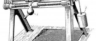
Antique foot operated lathe
There were no problems with the source of energy, since healthy and strong slaves were available in abundance. In more civilized times, such a machine was driven by a tightly stretched bowstring. But there was a significant limitation - the speed of revolutions fell as the bowstring untwisted, so in the Middle Ages models of foot-driven lathes appeared.
Design and principle of operation of a CNC lathe
They very vaguely resembled a sewing machine - because they included a traditional crank mechanism. This turned out to be a very positive change: the rotating workpiece now had no accompanying oscillatory movements, significantly complicating the work of the master and deteriorating the quality of processing.
However, by the beginning of the 16th century, the lathe still had a number of significant limitations:
Lathe with manual cable drive from a flywheel
- The cutter had to be held manually, so during prolonged metal processing the turner’s hand became very tired.
- The steady rest supporting long workpieces was attached separately from the machine, and therefore its installation and verification were quite lengthy.
- The problem of removing the chips was never solved: an apprentice was needed to periodically brush the chips off the master's hand.
- The issue of uniform movement of the cutter during processing was not resolved either: everything was determined by the qualifications and experience of the master.
The next few hundred years were spent designing a rotation drive for the moving center of the machine, in which the workpiece was mounted. The most successful was the design of Jean Besson, who was the first to use a water drive for these purposes.
The machine turned out to be quite cumbersome, but it was on it that threads were cut for the first time. This happened in the middle of the 16th century, and a few years later, Peter I’s mechanic Andrei Nartov invented a mechanized machine on which it was possible to cut threads with a variable speed of rotation of the moving center. A characteristic feature of Nartov’s machine was also the presence of a replaceable gear block.
Main nodes
Lathes are ideal for machining 3D parts using rotary cutting. An overview of a modern machine contains the parameters and characteristics of the main components:
- The bed is the main loaded element, the frame of the machine. They are made from durable and hard alloys; perlite is mainly used.
- A support is an island for mounting rotating tool heads or static tools.
- Spindle - acts as a workpiece holder. The main powerful rotation unit.
- Additional components: ball screws, sliding axes, lubrication mechanisms, coolant supply, air intakes from the working area, coolers.
A modern lathe contains drive systems consisting of complex control electronics and a motor, usually a synchronous one. Additional options allow you to remove chips from the working area, measure the tool, and supply coolant under pressure directly to the cutting area. The mechanics of the machine are selected individually for production tasks, and the cost of the equipment depends on this.
The support contains units for placing bearings, which are mounted on a ball screw (ball screw). Elements for contact with the sliding guides are also mounted on it. Lubricant in modern machines is supplied automatically, and its level in the tank is controlled.
In the first lathes, a person moved the tool and chose the direction of its movement. In modern models, all manipulations are carried out by the controller. It took several centuries to invent such a knot. Electronics have greatly expanded processing capabilities.
Notes[ | ]
- What is a Lathe Machine? History, Parts, and Operation (English). Brighthub Engineering
. Date accessed: March 26, 2022. - Clifford, Brian
A brief history of woodturning.
The Woodturner's Workshop
. Woodturners' Guild of Ontario. — “the first evidence of the lathe itself comes from the 3rd century BC but it is known that it was in use long before that. A flat wooden dish which stood on wooden legs was found in a pit grave at Mycenae dated at 1100 to 1400 BC… suggests that it could have been turned on a mandrel held between centers in a lathe. Against this view must be set the fact that there is no sign of turned grooves on the piece.” Access date: July 24, 2022. - Clifford, Brian
A brief history of woodturning.
The Woodturner's Workshop
. Woodturners' Guild of Ontario. — “The earliest piece from that was found at a site known as the “Tomb of the Warrior” at Corneto. This is a fragment of a wooden bowl, dated at around 700 BC, which shows “clear evidence of rounding and polishing on its outer surface and of hollow turning...” (Woodbury) Other Etruscan turned vessels were found on this site. … Excavations of a mound grave in Asia Minor (now Turkey) revealed two flat wooden dishes with decorative turned rims. These have been dated as from the 7th century BC." Access date: July 24, 2022. - Emperor's Ghost Army
(documentary). PBS. Time from the beginning of the source: 26:00. - Clifford, Brian
A brief history of woodturning.
The Woodturner's Workshop
. Woodturners' Guild of Ontario. — “The earliest information on the late dates from the 3rd century BC. This is a bas-relief carving on the wall of the grave of an Egyptian called Petrosiris.” Access date: July 24, 2022. - Murthy, S. Trymbaka.
Textbook of Elements of Mechanical Engineering (English). — ISBN 978-9380578576. - Nartov Andrey Konstantinovich 1693 - 1756: brief biography, years of life, activities (Russian). histrf.ru. Access date: January 26, 2022.
- Inimitable accuracy (Russian) // rusplt.ru.
- Andrey Konstantinovich Nartov - Inventions and inventors of Russia (Russian). www.inventor.perm.ru. Access date: January 26, 2019.
- Tomiyama, Testuo
Development of Production Technology and Machine Tools (presentation notes).
Pages 18—21 (English) (PDF). OpenCourseWare: TUDelft
.
TUDelft (February 16, 2016). — “1770 Jan Verbruggen Escaped to England with his Son Pieter Verbruggen (1734-1786) and Became Master Founder at Woolwich Arsenal.” Retrieved July 24, 2022. Archived July 25, 2022. 02. Ontwikkeling Fabricagetechnologie
[Lecture]. Delft, Netherlands: TUDelft.
Control
Recently, CNC lathes for metal - with numerical control - have become widespread. The controller controls the cutting process, monitors the position of the axes, and calculates the movement according to the specified parameters. Several cutting stages are stored in memory, right up to the finished part.
CNC lathes for metal can have process visualization, which helps to check the written program before the tool begins to move. The entire cut can be seen virtually and code errors can be corrected in time. Modern electronics control the axle load. The latest versions of the software allow you to identify a broken tool.
The technique for monitoring broken plates on a holder is based on comparing the graph of axle loads during normal operation and when the emergency threshold is exceeded. Tracking occurs in the program. Information for analysis is supplied to the controller by a drive system or a power sensor with the ability to digitize values.
History of turning
The oldest lathes were used in Egypt as far back as the Bronze Age. These were string lathes with reciprocating motion. Features of such designs:
- Their driving force was a person pulling one or the other end of a rope wound on a shaft mounted for rotation on two bearings.
- The workpiece was clamped at the end of the shaft, while another person held the cutting tool in his hands and pressed it against the workpiece.
In the middle of the 2nd millennium BC, a new design of lathe drive appeared, which lasted until the 16th century. It was a string drive, so it also used a cord wrapped around the drive shaft, but on one side it was attached to a foot pedal, and on the other to an elastic element (this could be a young tree bent in a special way). When a person pressed the pedal, he pulled the cord down, at the same time causing the shaft to rotate and the elastic element to compress. When the pressure on the pedal decreased, the spring element pulled the cord upward, while simultaneously turning the shaft in the opposite direction. Later, instead of wood, a spring-shaped arch was used, suspended from the ceiling.
Around 1500, the great Leonardo da Vinci improved the lathe drive, using rope and belt drives and at the same time gear drives - thus creating a lathe with continuous (irreversible) movement. The advent of the flywheel, which allows large amounts of energy to be stored, has made it easier to process increasingly harder materials.
Position sensors
The first machines with electronics had limit switches with microswitches to control extreme positions. Later, encoders began to be installed on the screw pair. Currently, high-precision rulers are used that can measure backlash of several microns.
Equipped with circular sensors and rotation axis. The spindle assembly could be controlled. This is required to implement the milling functions that were performed by the driven tool. The latter was often built into the turret.
The integrity of the tool is measured using electronic probes. They also make it easier to find reference points to start the cutting cycle. Probes can measure the geometry of the resulting contours of a part after processing and automatically make corrections that are included in repeated finishing.
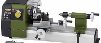
The simplest modern model
The TV 4 lathe is a training model with a simple drive mechanism. All control is done manually.
Handles:
- adjust the position of the tool relative to the axis of rotation;
- set the direction of thread cutting right or left;
- serve to change the speed of the main drive;
- determine the thread pitch;
- include longitudinal movement of the tool;
- are responsible for fastening the components: the tailstock and its quills, heads with cutters.
Flywheels move nodes:
- tailstock quill;
- longitudinal carriage.
The design includes a lighting circuit for the working area. A safety system in the form of a protective screen protects workers from chips. The design of the machine is compact, which allows it to be used in classrooms and service areas.
The TV4 screw-cutting lathe is a simple design that provides all the necessary components for a full-fledged design for metal processing. The spindle is driven through a gearbox. The tool is mounted on a support with mechanical feed and driven by a screw pair.
Types of turning equipment
Turret lathes are designed for products that require processing of several surfaces using various tools. In order not to have to install and configure each tool, turret heads are installed on such machines, which can have two or more slots for placing tools. Of course, servicing such a lathe is much more difficult than a conventional model, but this is fully compensated by the functionality of this unit. For example, popular models of such machines are 1E316P, 1G340PTs, 1P371, 1A341.
A rotary lathe is one of the types of lathes
Rotary turning machines are designed for processing workpieces characterized by a short length, significant weight, and large outer diameter. These include dimensional gears, flywheels, etc. The functionality of such lathes (for example, models 1512, 1541, 1550, 1L532 and others) allows them to perform various types of turning work: turning, boring, cutting grooves, end processing, etc. And if you equip such turning units with additional devices, they will become even more versatile: with their help it will be possible to perform some milling operations, cut threads, grind and perform a number of other technological actions.
Working parts of a multi-spindle machine
Multi-spindle machines belonging to the turning group are necessary for performing complex technological operations in mass production conditions. Workpieces that can be processed on such machines can be in the form of pipes, hexagonal, square and round rods, shaped profiles, etc. This technique is distinguished by its high rigidity of design and powerful drive, which allows processing with high productivity.
What is important is that such complex and functional equipment is maintained in exactly the same way as a conventional machine. The list of technological operations that can be performed on such a unit is quite extensive: boring, roughing and shaping, cutting and rolling threads, etc. The most popular models of such turning equipment are 1P365 and 1B140 machines.
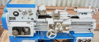
Screw-cutting lathe 16K20
Common models of turning machines, which gained wide popularity back in Soviet times, are screw-cutting lathes. Such machines, which can be found not only in almost any industrial enterprise, but also in school workshops, have gained their popularity due to the fact that with their help they can effectively perform a large list of technological operations.
Each such machine, regardless of the model, has a standard design consisting of the same type of components. Along with their functionality, screw-cutting lathe models are characterized by high safety, ease of operation and maintenance, which makes it possible to use them as units for equipping school workshops since the times of the USSR. The most famous and popular models of such turning equipment are machines 16K20, 16K50, 16B16A and 16P16P.
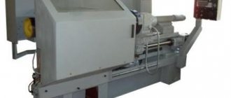
At enterprises that produce their products in large series and use blanks from shaped profiles and calibrated rods in production, automatic lathes are actively used. Such machines, which primarily perform turning operations in the longitudinal direction, cope with equal success in processing workpieces made of various metals: super-hard alloys, soft copper, etc.
On the domestic market, lathes are represented mainly by models from foreign manufacturers (Japan, South Korea, etc.). There are also some domestically produced models, for example 1M10DA.
Longitudinal turning machine 1M10DA
Dimensions
The spindle is controlled by an asynchronous motor. The maximum size of the workpiece can be in diameter:
- no more than 125 mm if processing is carried out over a caliper;
- no more than 200 mm if processing is carried out above the bed.
The length of the workpiece clamped at the centers is no more than 350 mm. The assembled machine weighs 280 kg, maximum spindle speed is 710 rpm. This rotation speed is decisive for finishing. Power is supplied from a 220V network with a frequency of 50 Hz.
Model features
The gearbox of the TV4 machine is connected to the spindle motor by a V-belt drive. Rotation is transmitted to the spindle from the gearbox through a series of gears. The direction of rotation of the workpiece can be easily changed by the phasing of the main motor.
The guitar serves to transmit rotation from the spindle to the calipers. It is possible to switch 3 feed speeds. Accordingly, three different types of metric threads are cut. The smoothness and uniformity of movement is ensured by the lead screw.
The handles set the direction of rotation of the headstock screw pair. The feed speeds are also set using the handles. The caliper moves only in the longitudinal direction. The components should be lubricated manually according to machine regulations. The gears take the lubricant from the bath in which they operate.
The machine has the ability to work manually. Flywheels are used for this. The rack and pinion gear engages with the rack. The latter is screwed to the frame. This design allows you to enable manual control of the machine if necessary. A similar flywheel is used to move the tailstock quill.