Various tools and equipment are used to process metal surfaces. Cylindrical grinding machines can be used to work with round parts. They are large in size, but have many advantages - ease of operation, high accuracy, several operating modes. But how does a cylindrical grinding machine work from an engineering point of view? What features do these devices have? And how to choose a machine for a production workshop or factory? These issues will be discussed in the article.
Basic information
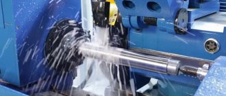
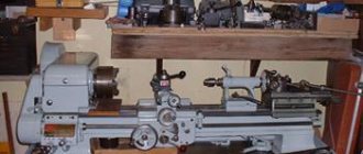
A cylindrical grinding machine is a device for automatically grinding metal products. The installation looks like a large table on which additional grinding equipment is installed. The operating principle of cylindrical grinding machines is simple. Using headstocks or a carriage, the metal part to be processed is installed in the working area. After this, the grinding wheel is started and rotates around its axis. The circle approaches the workpiece, which leads to stripping of the metal workpiece.
Using a cylindrical grinding machine, you can process cylindrical, conical and end workpieces, as well as large holes. By design, there are centered and centerless models. For center models, the workpiece is secured using special grooves. In centerless models, the workpiece is fixed in the working area of the machine using a clamping carriage. A cylindrical grinding machine performs the following tasks: abrasive rubbing of the surface of the workpiece, removing an excess layer of metal, eliminating irregularities on the metal surface.
Elements of cylindrical grinding systems
- Desktop. Acts as a base on which all the main elements are attached. The workbench may have small wheels that are used to transport the unit. The work table is made of durable metal alloys, as are other elements of the grinding system.
- Headstock grooves (center models). Used for fastening parts on the desktop. The grooves can rotate around their axis, which allows you to process the workpiece over its entire area + improves the quality of grinding. Some grooves can also move in the longitudinal direction, which allows you to change the position of the part on the work table directly during processing. The head slots can be movable - this allows you to change the angle of the workpiece on the work table. This makes it possible to grind conical workpieces.
- Carriage (centerless models). The carriage is also used for fastening parts on the work table. The main difference from the headstock grooves is that the carriage does not have its own axis of rotation (it can only be moved in the horizontal direction). To process the workpiece from different sides, the workpiece itself is rotated on the carriage.
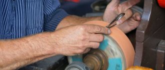
- Abrasive disc wheel. Located in a perpendicular direction relative to the location of the workpiece on the work table. During operation, it acts as an abrasive with which processing is performed. Abrasive discs come in different shapes. Simple machines have a fixed disk arrangement. The universal cylindrical grinding machine has a movable disc wheel, which makes the installation more versatile.
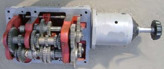
- Drive unit. Used to move the abrasive wheel while the system is operating. The drive can be mechanical, hydraulic and electric. Large systems are usually equipped with an electric drive, which simplifies the procedure for moving the disk during operation. Small machines have a mechanical or hydraulic drive, which reduces electricity consumption.
- Electric motor. Acts as an energy source that powers all the main elements of the installation (rotating slots-headstocks, abrasive disc-wheel, etc.). If the machine is equipped with an electric drive, then the engine also powers this element. Electric motors usually have a power ranging from 5 to 15 kilowatts, although more powerful units are also available. Modern electric motors usually have additional protective elements to avoid system overheating.
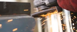
- Cooling system. During processing, serious heating of the workpiece occurs due to friction. To avoid overheating of the workpiece, many modern machines are equipped with a cooling system. It looks like small taps that are installed in the core. The taps are connected to the refrigerant (the refrigerant is usually water). During processing of the part, the valves are activated, which leads to the spraying of coolant in the core.
Main settings
When choosing equipment, you should take into account its type, which determines many important grinding parameters. The main parameters include:
- Possible dimensions of the installed center. In the case of a centerless model, an important indicator is the size of the table.
- The diameter of the circle and the speed of its rotation. Universal design options can be used to produce parts of various shapes; they can be conical.
The passport contains all important information. The drawing and passport allow you to determine what technical characteristics the design has. The drawings are drawn up taking into account GOST, just like the passport.
The above information should be taken into account when choosing a model; the diagram of a cylindrical grinding machine reflects all its features. Therefore, to determine important points, you should consider the drawings and passport drawn up in accordance with GOST.
Features of cylindrical grinding machines
Control is carried out manually using mechanical and hydraulic drives. Also, many modern installations are equipped with a numerical control (CNC) panel, which allows automation of most production processes. This not only simplifies the worker’s task, but also has a beneficial effect on the quality of processing.
To be allowed to install (both with and without a CNC panel), the worker must undergo appropriate training. He must also undergo training regarding workplace safety rules. During operation, a person must be careful not to damage the part and harm his health. Depending on the design, the following types of installations are distinguished:
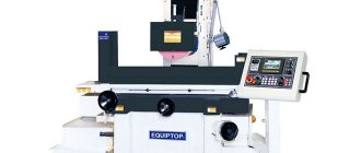
- Simple machine. In such installations, you can only change the angle of the table on which the main part is fixed, and the grinding disk has a fixed position. This makes it possible to process cone-shaped parts with a small apex angle. The fixed location of the disk impairs the versatility of the system, but significantly reduces its cost. Therefore, in the case of small industries (auto repair shops, home construction), purchasing a simple machine may be a justified decision.
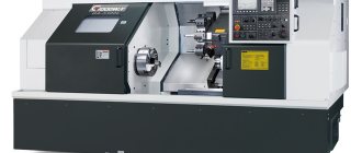
- Universal cylindrical grinding machine. On such systems, both the table and the processing disk can be rotated. This allows you to grind all types of parts (flat, conical, end, variable diameter), as well as individual holes inside workpieces. A universal cylindrical grinding machine is usually equipped with a CNC, which can significantly increase the quality of processing. Such installations are more expensive than simple systems, and they are usually used in industry (mechanical engineering, repair of ships or aircraft, weapons production).
Purpose
Cylindrical grinding machines are used to process the outer cylindrical surface; the workpiece is fastened in the centers and in the chuck. In this case, longitudinal and transverse feeding can be carried out to achieve the desired result. The universal version is suitable for various sizes; some types can be used in industry to produce particularly large parts.
During operation of a universal machine with centers, the direction of rotation of the workpiece is opposite to the direction of rotation of the abrasive material. Such models can be used in various types of production.
It is worth noting that the cylindrical grinding machine is used at the final stage of production. Centerless and other types of models carry out grinding after turning, milling, drilling and so on.
Types of grinding
Grinding using a cylindrical grinding machine can be carried out by three main methods - plunging, shoulder processing, longitudinal working stroke. Each of the techniques has several additional modifications, so there are many more actual processing scenarios.
Basic processing techniques
- Longitudinal grinding. The workpiece is installed in special grooves, which perform rotational movements during operation. The grooves move at low speed along (the speed is adjusted manually or using CNC). This leads to two effects during operation - the part not only rotates, but also moves along its axis. The polishing wheel is also turned on to perform the grinding. Due to the longitudinal stroke, the part is processed over its entire area, which simplifies its processing. The optimal depth is 0.05-0.1 mm.
- Longitudinal depth grinding. This method repeats the previous technology with one small difference - during operation the depth is from 0.1 to 0.4 millimeters. This allows you not only to clean the surface, but also to cut off the unnecessary layer of metal from the workpiece. Deep processing speeds up cleaning, but it is not suitable for working with soft metal alloys (brass, bronze, aluminum and others).
- Double longitudinal grinding. Two processing disks are installed on the machine equipment, and the processing itself is performed using the longitudinal stroke method. The first disc has a larger grain compared to the second. A small spacer can be installed between the discs to simplify the processing procedure. The meaning of such a system is this: the part is cleaned on the first disk, where the unnecessary layer of metal is cut off. Then it goes to the second disk, where it is polished and final cleaned.
- Plunge grinding. The metal workpiece is mounted in grooves that perform rotational movements during operation. The grooves are static (that is, the part does not make longitudinal movements). For processing, a wide wheel-disc is used, which is much longer than the workpiece itself. Grinding is performed as follows: the part is brought to a rotating wheel, which leads to grinding of the workpiece along its entire length. The technology is suitable for processing shaped or identical parts and solid sheets that do not have small recesses or recesses.
- Shoulder grinding. The technique is a combination of longitudinal and plunge grinding technologies. Shoulder grinding is used to grind long, rough parts that are difficult to process using only one of the standard grinding technologies. The mechanics of the process look like this. The part is mounted in special recesses that rotate it and move it horizontally. For the processing itself, one or more grinding discs are used. During penetration, one of the sections of the part is processed using the plunge-cut grinding method. Then a longitudinal stroke is performed, which makes it possible to process another part of the workpiece. If necessary, stop the machine and replace the abrasive disc (when working with grooves, recesses, holes).
Rough and fine grinding
During rough grinding, a layer of a certain thickness is cut off from the metal surface. The main purpose of roughing is to reduce the size of the part (in an individual fragment or over the entire area).
During finishing processing, polishing is performed, as well as the removal of defects (burrs, cracks, sharp corners). Rough and finishing grinding can be performed on different or on the same machine.
A universal cylindrical grinding machine performs double grinding - the first disc removes excess metal, and the second layer performs final polishing.
Device
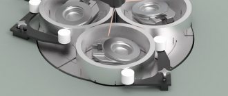
Equipment with fixed knives is used for automatic lines. A cylindrical grinding machine for metal can have different configurations. The most common arrangement is with 3 types of cartridges. These are cartridge ones with 1-2 tables, center ones with 1-2 tables. There are also centerless installations with fixed or movable knives and a fixed shoe.
The installation axis of the part will be constant in any position of the working grinding wheel, which guarantees high quality processing. When the unit wears out, no further adjustment is needed, and no loss of grinding quality is observed. However, the design of such machines is more complex. Machines with fixed heads are characterized by increased rigidity, but the dimensions of the unit are smaller, which allows the equipment to be used not only in workshops, but also in small workshops.
Main models
- Model 3151. Has manual control, no CNC panel. Can grind all main types of workpieces - hollow, flat, cylindrical, end. Can also be used for processing cone-shaped workpieces with a slight angle of inclination. Model 3151 is not suitable for large factories, but it can be used in small batch production.
- Model 3M151. It is a modification of model 3151. Equipped with automation, which helps control the system both manually and automatically. Model 3M151 can perform all basic types of grinding of rounded workpieces. Can be used in small industries, workshops, large factories and so on.
- Model 3B161. Equipped with hydraulics and automation. Can perform all basic types of grinding (can also perform shoulder grinding). Suitable for serial processing, although if necessary, model 3B161 can be converted for single production.
- Model G25A-35CNC. Has an electronic control mode (CNC). The model is equipped with advanced electronics and can perform complex grinding options in a fully automatic mode. High price, but good technical indicators (strength, reliability, stability, shelf life).
Main technical characteristics
There are basic technical characteristics that are reflected in the passport and drawing. Based on GOST, the following information is displayed:
- Power is indicated in kW. Determines the performance of the machine.
- The supplied voltage determines whether the equipment can be used in a given situation. GOST determines that the indicator is indicated in Volts. For industrial use, a model with a 380 V power supply is suitable, but for domestic use, a 220 V power supply is suitable.
- Worker size has become. Centerless grinding machines can be used in certain applications.
- Grinding wheel diameter. The circle has standard sizes, which are selected according to GOST.
- The nominal speed is also often determined in GOST. It is important because it determines the speed of rotation of the circle.
Such points should be taken into account when choosing a cylindrical grinding machine.
Connecting and landing bases of the 3M151F2 cylindrical grinding machine
Technical characteristics of the 3M151F2 cylindrical grinding machine . The largest dimensions of the installed workpiece: diameter 200 mm, length 700 mm, diameter of the workpiece processed with active control, 0-85 mm, workpiece rotation speed 50-500 min-1 (steplessly adjustable), grinding wheel speed no more than 50 m/s, working feeds of the grinding head for pre-processing 0.2-0.12 mm/min, final 0.1-0.6 mm/min, finishing 0.02-0.12 mm/min, fast approach speed of the grinding head 1700-930 mm/min, table movement speed 0.05–5 m/min (number of steps 10), overall dimensions of the machine 4950 x 2400 x 2170 mm.
CNC is specialized for grinding machines. UE input is via decade switches. Dimensions in the program program are specified in absolute values. According to the UE, eight stages of the workpiece can be ground. The number of programmable coordinates is 2. The work is performed sequentially for each coordinate. The machine is equipped with two measuring devices and corresponding correction systems: to determine the deviation of the dimensions of the workpiece and the circle. Monitoring of diametric wheel wear (X coordinate) is performed and corrected indirectly when measuring the workpiece during processing with an active control device. Control of the base end of the workpiece (Z coordinate) is carried out by an axial orientation device. This control is needed to link the workpiece to the coordinate system of the machine (for example, in the case of measuring the depth of end holes). The device has a probe, the moment it touches the workpiece, the “zero” of the machine table position sensor is corrected. Discreteness of movement along coordinates: X - 0.001 mm, Y - 0.01 mm. The CNC has a digital display.
Basic mechanisms and movements in the machine . The rigid frame A of the machine (Fig. 171, a) has guides along which the table F makes reciprocating movements, carrying an upper rotary table that can be rotated at an angle. The workpiece is installed in the centers of the front B and rear E stock. She gets a circular feed motion. The grinding head B moves along the transverse guides of the frame, on the body of which the transverse feed mechanism D is mounted. The grinding spindle, in addition to rotational movement, has axial movement in automatic mode. Auxiliary movements : input and output of measuring instruments into the processing area, manual movements of the table and grinding headstock, approach and removal of the tailstock quill, movement of the follower stop, longitudinal movement and feeding of the diamond tool onto the wheel during dressing, which is performed by device B. The machine is equipped with a device for balancing the circle.
The program control system is positional, closed. The program is entered using ten-day switches; according to the program, up to eight stages of the workpiece can be sanded. The machine is equipped with two measuring devices and two correction systems: to determine deviations in the dimensions of the workpiece and the circle. Monitoring of diametric wheel wear (along the X axis) is carried out and corrected indirectly when measuring the workpiece during grinding with a wide-range active control device. Control of the base end (along the Z' axis) is carried out with an axial orientation device to link the workpiece to the coordinate system of the machine (for example, when changing the centering depth). At the moment the workpiece touches the probe of the device, the “zero” of the table position sensor is corrected. The discreteness of programmable movement along the X axis is 0.001 mm, and along the Z' axis - 0.1 mm.
The machine operating cycle is adopted according to the following program. The electric motors of the hydraulic system, lubrication pumps and the magnetic separator of the grinding wheel drive are turned on. The measuring bracket is raised, the tailstock quill is retracted, and the workpiece is clamped in the centers. By pressing the “Automatic” button: the grinding head moves to the extreme position controlled by the limit switch; the table takes a position according to the coordinate of the end of the first grinding stage, without taking into account the alignment correction; a measuring bracket and an axial orientation device are brought in, the probe of which rests on the workpiece, the table moves until the base end of the workpiece touches the probe of the axial orientation device; the origin is aligned along the Z' coordinate along the installed workpiece; The probe of the axial orientation device is removed.
The grinding head moves at an approach speed of 1800 mm/min until its position sensor engages with the follower stop and slows down the speed by 2 times. Workpiece rotation and coolant supply are turned on. 2-3 mm before reaching the specified size, the speed of movement of the headstock slows down to 6 mm/min.
Changing the speed of movement of the grinding headstock from forced to roughing occurs at the command of the contact relay of the wheel with the workpiece or from the headstock position sensor when the allowance on the workpiece is less than 0.2 mm. Switching of the grinding headstock from forced feed to rough feed is carried out at the command of the position sensor. When switching it to the finishing feed, the jaws of the measuring clamp close on the workpiece and the transition to the finishing feed and the end of processing is achieved by the clamp. When machining discontinuous surfaces, the final machining is carried out at the command of the sensor.
Having sanded one step, the table moves and the next step is polished. Having polished the last step, the headstock moves to its extreme position and the measuring device is retracted. The shaft grinding cycle is completed.
The longitudinal movement of the table is carried out by a hydraulic drive of the machine using a hydraulic cylinder Ts1 or manually by a handwheel 9 through gears 14/62, 12/48 and rack and pinion. The movement of the table by hydraulic drive is interlocked with its manual movement. Hydraulic cylinder C2 disengages the shaft from the wheel z = 14.
The workpiece rotation is driven from an adjustable DC electric motor M2 via a V-belt drive with pulley diameters of 74/122 and 63/168. The rotation speed of the workpiece is infinitely adjustable within the range of 50-500 rpm.
Transverse feeds of the grinding headstock are carried out manually and automatically. The installation drive of the grinding head is carried out manually using handwheel 8 of shaft VI, through conical wheels 39/89 of shaft VII, a 2/40 worm pair and a rolling screw nut with p = 10 mm.
The machine has two rapid feeds of 1800 and 900 mm/min. Automatic working feed is provided by an adjustable DC electric motor MZ through worm pairs 2/30 and 2/40 when the electromagnetic clutch Ml is turned on, bevel wheels 39/39, worm pair 2/40 and a rolling screw nut. The rotation speed of the electric motor is controlled by a tachogenerator.
The axial movement of the grinding wheel spindle for grinding the ends supplies oil to the C5 cylinder and thereby moves the piston-rack, which turns the wheel z = 17, shaft XIV and cam 4, which, acting on the plunger 5 and the lever system 6, moves the spindle VIII. After the wheel contacts the end of the workpiece, the forced feed stops, and the end is grinded. The spindle returns to its original position by spring 7.
Automatic wheel correction is carried out where compensation for its wear is provided - radial correction. The diamond is fed to the grinding wheel automatically or manually by rotating the handwheel 2 on shaft V with wheels 22/72, 27/27 and a lead screw with p=2 mm. During automatic straightening from the hydraulic system, the plunger with pawl 1 turns the ratchet wheel z=200 on screw III. The angle of rotation is adjusted by turning. The longitudinal movement of the diamond is carried out by a central locking hydraulic cylinder. The body is moved on the carriage at an angle of 45° by a hydraulic cylinder C4, resting with a probe on a straight-line copier 3, providing single-pass or double-pass dressing of the wheel. The position of the copier is adjusted with a screw with p = 1.5 mm.
Tailstock. The quill is removed hydraulically by moving the rack piston or manually by turning the wheel shaft z=24. The workpiece is clamped in the centers by a spring. A mechanism for bringing out the taper on the workpiece is mounted on the headstock due to the fact that the tapered hole for the center is bored out with eccentricity relative to the outer diameter of the quill. When the M5 electric motor is turned on, it is possible to feed the workpiece onto the wheel by turning the quill.
The hydraulic system provides longitudinal reciprocating movement of the table with ten fixed speeds, longitudinal movement of the measuring bracket, opening of the jaws of the measuring bracket, input and output of the probe of the axial orientation mechanism, input and output of measuring instruments, removal of the tailstock quill, control of the grinding wheel dressing device, and spindle movement. grinding headstock for trimming, eliminating the gap in the mechanism for rapid supply of the grinding headstock, disabling the mechanism for manual movement of the table, lubricating the bearings of the headstock spindles and table guides.